Maspack Reference Manual
Last update: September, 2021
Contents
- Preface
- 1 Properties
-
2 Rendering
- 2.1 Overview
- 2.2 Viewers
-
2.3 The Renderer Interface
- 2.3.1 Drawing single points and lines
- 2.3.2 Drawing single triangles
- 2.3.3 Colors and associated attributes
- 2.3.4 Drawing using draw mode
- 2.3.5 Drawing solid shapes
- 2.3.6 Shading and color mixing
- 2.3.7 Vertex coloring, and color mixing and interpolation
- 2.3.8 Changing the model matrix
- 2.3.9 Render properties and RenderProps
- 2.3.10 Screen information and 2D rendering
- 2.3.11 Depth offsets
- 2.3.12 Maintaining the graphics state
- 2.3.13 Text rendering
- 2.4 Render Objects
- 2.5 Texture mapping
- 2.6 Mesh Renderers
- 2.7 Object Selection
Preface
Maspack (modeling and simulation package) is a set of Java packages to support physical modeling and simulation. The purpose of this guide is to document some of these packages in detail, one package per chapter. At present, the guide is incomplete and documents only the property and rendering packages. More chapters will be added as resources permit.
Chapter 1 Properties
The maspack property package (maspack.properties) provides a uniform means by which classes can export specific attributes and information about them to application software. The main purpose of properties is to
-
1.
Provide generic code for accessing and modifying attributes.
-
2.
Remove the need for "boiler-plate" code to read or write attributes from persistent storage, or modify them by other means such as a GUI panel.
The property software uses Java reflection to obtain information about a property’s value and its associated class, in a manner similar to that used by the properties of Java Beans.
1.1 Accessing Properties
Any class can export properties by implementing the interface HasProperties:
Each property is associated with a name, which must be a valid Java identifier. The getProperty() method returns a Property handle to the named property, which can in turn be used to access that property’s values or obtain other information about it. getAllPropertyInfo() returns a PropertyInfoList providing information about all the properties associated with the class.
A Property handle supplies the following methods:
- get()
-
Returns the property’s value. As a rule, returned returned values should be treated as read-only.
- set()
-
Sets the property’s value (unless it is read-only, see Section 1.2).
- getRange()
-
Returns a Range object for a property (see Section 1.1.1), which is used to determine which values are admissible to set. If all values are admissible, getRange() can return null.
- getHost()
-
Returns the object to which this property handle belongs.
- getInfo()
-
Returns static information about this property (see Section 1.2).
A simple example of property usage is given below. Assume that we have a class called DeformableModel which contains a property called stiffness, and we want to set the stiffness to 1000. This could be done as follows:
Of course, DeformableModel will likely have a method called setStiffness that can be used to set the stiffness directly, without having to got through the Property interface. However, the purpose of properties is not to facilitate attribute access within specially constructed code; it is to facilitate attribute access within generic code that is hidden from the user. For instance, suppose I want to query a property value from a GUI. The GUI must obtain the name of the desired property from the user (e.g., through a menu or a text box), and then given only that name, it must go and obtain the necessary information from the object exporting that property. A Property allows this to be done in a manner independent of the nature of the property itself.
1.1.1 Why Property Handles?
In theory, one could embed the methods of Property directly within the HasProperties interface, using methods with signatures like
The main reason for not doing this is performance: a property handle can access the attribute quickly, without having to resolve the property’s name each time.
Each property handle contains a back-pointer to the object containing, or hosting, the property, which can be obtained with the getHost() method.
1.2 Property Ranges
A Range object supplies information about what values a particular Property can be set to. It contains the following methods:
- isValid()
-
Returns true if obj is a valid argument to the property’s set method. The optional argument errMsg, if not null, is used to return an error message in case the object is not valid.
- makeValid()
-
Trys to turn obj into a valid argument for set(). If obj is a valid argument, then it is returned directly. Otherwise, the method tries to return an object close to obj that is in the valid range. If this is not possible, the method returns Range.IllegalValue.
- intersect()
-
Intersects the current range with another range and placed the result in this range. The resulting range should admit values that were admissible by both previous ranges.
- isEmpty()
-
Returns true if this range has no admissible values. This is most likely to occur as the result of an intersection operation.
Possible usage of a range object is shown below:
Two common examples of Range objects are DoubleInterval and IntegerInterval, which implement intervals of double and integer values, respectively. Ranges are also Clonable, which means that they can be duplicated by calling range.clone().
1.3 Obtaining Property Information
Additional information about a property is available through the PropertyInfo interface, which can be obtained using the getInfo() method of the property handle. Information supplied by PropertyInfo is static with respect to the exporting class and does not change (unlike the property values themselves, which do change). Such information includes the property’s name, whether or not it is read-only, and a comment describing what the property does.
Some of the PropertyInfo methods include:
Property information can also be obtained directly from the exporting class, using getAllPropertyInfo(), which returns information for all the properties exported by that class. This information is contained within a PropertyInfoList:
For example, suppose we want to print the names of all the properties associated with a given class. This could be done as follows:
1.4 Exporting Properties from a Class
As indicated above, a class can export properties by implementing the interface HasProperties, along with the supporting interfaces Property, PropertyInfo, and PropertyInfoList. The class developer can do this in any way desired, but support is provided to make this fairly easy.
The standard approach is to create a static instance of PropertyList for the exporting class, and then populate it with PropertyInfo structures for the various exported properties. This PropertyList (which implements PropertyInfoList) can then be used to implement the getProperty() and getAllPropertyInfo() methods required by HasProperties:
Information about specific properties should be added to PropertyList within a static code block (second line in the above fragment). This can be done directly using the method
but this requires creating and initializing a PropertyInfo object. An easier way is to use a different version of the add method, which creates the required PropertyInfo structure based on information supplied through its arguments. In the example below, we have a class called ThisHost which exports three properties called visible, lineWidth, and color:
The values for the three properties are stored in the fields myLineWidth, myVisibleP, and myColor. Default values for these are defined by static fields.
A static instance of a PropertyList is created, using a constructor which takes the exporting class as an argument (in Java 1.5, the class object for a class can be referenced as ClassName.class). Information for each property is then added within a static block, using the convenience method
The first argument, nameAndMethods, is a string which gives the name of the property, optionally followed by whitespace-separated names of the accessor methods for the property’s value:
These accessor methods should have the signatures
If any of the methods are not specified, or are specified by a ’*’ character, then the system with look for accessor methods with the names getXxx, setXxx, and getXxxRange, where xxx is the name of the property. If no getRangeMethod is defined (and no numeric range is specfied in the options argument string, as described below), then the property will be assumed to have no range limitations and its getRange() method will return null.
The second argument, description, gives a textual description of the property, and is used for generating help messages or tool-tip text.
The third argument, defaultValue, is a default property value, which is used for automatic initialization and for deciding whether the property’s value needs to be written explicitly to persistent storage.
An extended version of the add method takes an additional argument options:
The options argument is a sequence of option tokens specifing various property attributes, each of which can be queried using an associated PropertyInfo method. Token are separated by white space and may appear in any order. Some have have both long and abbreviated forms. They include:
- NW, NoAutoWrite
-
Disables this property from being automatically written using the PropertyList methods write and writeNonDefaults (Section 1.5). Causes the PropertyInfo method getAutoWrite() to return false.
- AW, AutoWrite (Default setting)
-
Enables this property to be automatically written using the PropertyList methods write and writeNonDefaults (Section 1.5). Causes the PropertyInfo method getAutoWrite() to return true.
- NE, NeverEdit
-
Disables this property from being interactively edited. Causes the PropertyInfo method getEditing() to return Edit.Never.
- AE, AlwaysEdit (Default setting)
-
Enables this property to be interactively edited. Causes the PropertyInfo method getEditing() to return Edit.Always.
- 1E, SingleEdit
-
Enables this property to be interactively edited for one property host at a time. Causes the PropertyInfo method getEditing() to return Edit.Single.
- XE, ExpandedEdit
-
Indicates, where appropriate, that the widget for editing this property can be expanded or contracted to conserve GUI space, and that it is initially expanded. Causes the PropertyInfo method getWidgetExpandState() to return ExpandState.Expanded. This is generally relevant only for properties such as CompositeProperties (Section 1.4.2) whose editing widgets have several sub-widgets.
- CE, ContractedEdit
-
Indicates, where appropriate, that the widget for editing this property can be expanded or contracted to conserve GUI space, and that it is initially contracted. Causes the PropertyInfo method getWidgetExpandState() to return ExpandState.Contracted. This is generally relevant only for properties such as CompositeProperties (Section 1.4.2) whose editing widgets have several sub-widgets.
- NS, NoSlider
-
Indicates that a slider should not be allowed in the widget for editing this property. Causes the PropertyInfo method isSliderAllowed() to return false. In order for the editing widget to contain a slider, the property must also have both a numeric value and a defined range.
- DX, DimensionX
-
Sets the numeric dimension of this property to X. The dimension can be queried using the PropertyInfo method getDimension(). For properties which are non-numeric or do not have a fixed dimension, the dimension will be returned as -1. Note the for some numeric properties, the dimension can be determined automatically and there is no need to explicitly specify this attribute.
- SH, Sharable
-
Indicates that the property value is not copied internally by the host and can therefore be shared among several hosts. This may improve memory efficiency but means that changes to the value itself may be reflected among several hosts. This attribute can be queried by the PropertyInfo method isSharable().
- NV, NullOK
-
Indicates that the property value may be null. By default, this is false, unless the default value has been specified as null. Whether or not a property may be set to null is particularly relevant in the case of CompositeProperties (Section 1.4.2), where one may choose between setting individual subproperties or setting the entrie structure to null altogether.
- %fmt
-
A printf-style format string, beginning with %, used to format numeric information for this property’s value, either in a GUI or when writing to persistent storage. A good general purpose format string to use is often "%.6g", which specifies a free format with six significant characters.
- [l,u]
-
A numeric range interval with a lower bound of l and an upper bound of u. If specified, this defines the value returned by PropertyInfo.getDefaultNumericRange(); otherwise, that method returns null. If a getRangeMethod is not defined for the property, and the property has a numeric type, then the default numeric range is returned by the property’s Property.getRange() method. The default numeric range is also used to determine bounds on slider widgets for manipulating the property’s value, in case the upper or lower limits returned by the Property.getRange() method are unbounded. The symbol inf can be used in an interval range, so that [0,inf] represents the set of non-negative numbers.
The following code fragment shows an example of using the option argument:
The property named radius is given a numeric format string of
"%8.3f", a numeric range in the interval ![]() , and set so
that it will not be displayed in an automatically created GUI panel.
, and set so
that it will not be displayed in an automatically created GUI panel.
1.4.1 Read-only properties
A property can be read-only, which means that it can be read but not set. In particular, the set() for a read-only Property handle is inoperative.
Read-only properties can be specified using the following PropertyList methods:
These are identical to the add methods described above, except that the nameAndMethod argument includes at most a get accessor, and there is no argument for specifying a default value.
The method getAutoWrite() also returns false for read-only properties (since it does not make sense to store them in persistent storage).
1.4.2 Inheriting Properties from a superclass
By default, a subclass of a HasProperties class inherits all the properties exported by the class exports all the properties exported by it’s immediate superclass.
Alternatively, a subclass can create its own properties by creating it’s own PropertyList, as in the code example of Section 1.3:
and none of the properties from the superclass will be exported. Note that it is necessary to redefine getAllPropertyInfo() so that the instance of myProps specific to ThisHost will be returned.
If one wishes to also export properties from the superclass (or some other ancestor class), then a PropertyList can be created which also contains property information from the desired ancestor class. This involves using a different constructor, which takes a second argument specifying the ancestor class from which to copy properties:
All properties exported by Ancestor will now also be exported by ThisHost.
What if we want only some properties from an ancestor class? In that case, we can edit the PropertyList to remove properties we don’t want. We can also replace properties with new ones with the same name but possibly different attributes. The latter may be necessary if the class type of a property’s value changes in the sub-class:
1.5 Composite Properties
A property’s value may itself be an object which exports properties; such an object is known as a composite property, and its properties are called subproperties.
Property handles for subproperties may be obtained from the top-level exporting class using getProperty(), with successive sub-property names delimited by a ’.’ character. For example, if a class exports a property textureProps, whose value is a composite property exporting a sub-property called mode, then a handle to the mode property can be obtained from the top-level class using
which has the same effect as
Composite properties should adhere to a couple of rules. First, they should be returned by reference; i.e., the hosting class should return a pointer to the original property, rather than a copy. Secondly, they should implement the CompositeProperty interface. This is an extension of HasProperties with the following methods:
These methods can be easily implemented using local variables to store the relevant information, as in
and similarly for the property information.
The purpose of the CompositeProperty interface is to allow traversal of the composite property tree by the property support code.
The accessor method that sets a composite property within a host should set it’s host and property information. This can be done using using the setPropertyHost and setPropertyInfo methods, as in the following example for a compound property of type TextureProps:
Alternatively, the same thing can be done using the static convenience method PropertyUtils.updateCompositeProperty:
If a composite property has a number of subclasses, it may optionally implement the static method
which returns an array of the class types of these subclasses. This can then be used by the system to automatically create GUI widgets that allow different instances of these subclasses to be selected.
1.6 Reading and Writing to Persistent Storage
Properties contain built-in support that make it easy to write and read their values to and from persistent storage.
First, PropertyInfo contains the methods
which allow an individual object value to written to a PrintStream or scanned from a ReaderTokenizer.
Second, if the host object maintains a PropertyList, it can use the convenience method
to write out values for all properties for which getAutoWrite() returns true. Properties will be written in the form
where value is the output from the writeValue method of the PropertyInfo structure.
To economize on file space, there is another method which only writes out property values when those values differ from the property’s default value:
Again, values are written only for the properties for which getAutoWrite() returns true. The method returns false if not property values are written.
To read in property values, their are the methods
where the former will inspect the input stream and scan in any recognized property of the form propertyName = value (returning true if such a property was found), while the latter will check the input for a property with a specific name (and return true if the specified property was found).
1.7 Inheritable Properties
Suppose we have a hierarchical arrangement of property-exporting objects, each exporting an identical property called stiffness whose value is a double (properties are considered identical if they have the same name and the same value type). It might then be desirable to have stiffness values propagate down to lower nodes in the hierarchy. For example, a higher level node might be a finite element model, with lower nodes corresponding to individual elements, and when we set stiffness in the model node, we would like it to propagate to all element nodes for which stiffness is not explicitly set. To implement this, each instance of stiffness is associated with a mode, which may be either explicit or inherited. When the mode is inherited, stiffness obtains its value from the first ancestor object with a stiffness property whose mode is explicit.
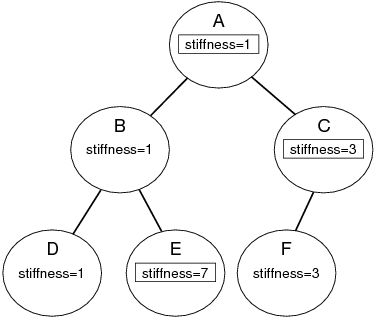
This is an example of property inheritance, as illustrated by Figure 1.1. Stiffness is explicitly set in the top node (A), and its value of 1 propagates down to nodes B and D whose stiffness mode is inherited. For node C, stiffness is also explicitly set, and its value of 4 propagate down to node F.
Another common use of property inheritance is in setting render properties: we might like some properties, such as color, to propagate down to descendant nodes for which a color has not been explicitly set.
To state things more generally: any property which can be inherited is called an inheritable property, and is associated with a mode whose value is either explicit or inherited. The basic operating principle of property inheritance is this:
Important:
An inherited property’s value should equal that of the nearest matching ancestor property which is explicitly set.
Other behaviors include:
-
•
Setting a property’s value (using either the set accessor in the host or the set method of the Property handle) will cause its mode to be set to explicit.
-
•
A property’s mode can be set directly. When set to explicit, all descendant nodes in the hierarchy are updated with the property’s value. When set to inherited, the property’s value is reset from the first explicit value in the ancestry, and then propagated to the descendants.
-
•
When a new node is added to the hierarchy, all inherited properties within the node are updated from the ancestry, and then propagated to the descendants.
If a property is inheritable, then the isInherited() method in its PropertyInfo structure will return true, and it’s property handle will be an instance of InheritableProperty:
Valid modes are PropertyMode.Explicit, PropertyMode.Inherited, and PropertyMode.Inactive. The latter is similar to Inherited, except that setting an Inactive property’s value will not cause its mode to be set to Explicit and its new value will not be propagated to hierarchy descendants.
The hierarchy structure which we have been describing is implemented by having host classes which correspond to hierarchy nodes implement the HierarchyNode interface.
These methods should be implemented as wrappers to the underlying hierarchy implementation.
1.8 Exporting Inheritable Properties
The property package provides most of the code required to make inheritance work, and so all that is required to implement an inheritable property is to provide some simple template code within its exporting class. We will illustrate this with an example.
Suppose we have a property called “width” that is to be made inheritable. Then addition to it’s value variable and set/get accessors, the host class should provide a PropertyMode variable along with set/get accessors:
The call to PropertyUtils.setModeAndUpdate() inside the set method ensures that inherited values within the hierarchy are properly whenever the mode is changed. If the mode is set to PropertyMode.Explicit, then the property’s value needs to be propagated to any descendent nodes for which it is inherited. If the mode is set to PropertyMode.Inherited, then the property’s value needs to be obtained from the ancestor nodes, and then also propagated to any descendent nodes for which it is inherited.
As mentioned in the previous section, explicitly setting a property’s value using the set accessor should cause it’s property mode to be set to Explicit and the new value to be propagated to hierarchy descendents. This can be accomplished by using PropertyUtils.propagateValue within the set accessor:
The actual creation of an inherited property can be done using the PropertyList methods
instead of the add or addReadOnly methods. The nameAndMethods argument may now specify up to five method names, corresponding, in order, to the get/set accessors for the property value, the getRange accessor, and the get/set accessors for the property’s mode. If any of these are omitted or specified as ’*’, then the system searches for names of the form getXxx, setXxx, getXxxRange, getXxxNode, and setXxxMode, where xxx is the property name.
Finally, the host objects which actually correspond to hierarchy nodes must implement the HierarchyNode interface as described in the previous section, and any routine which adds a node to the hierarchy must also implement the following code fragment:
This ensures that when a node is added, all property values within and beneath it are made consistent with the inheritance hierarchy.
1.9 Inheritable and Composite Properties
Property inheritance is not currently implemented for CompositeProperty objects, in order to avoid confusion of the inheritance rules. Suppose a class exports a composite property A, which in turn exports an inheritable property B. Now suppose that A is an inheritable property with its mode is set to Inherited. Then the entire structure of A, including the value of B and its mode, is inherited, and it is no longer possible to independently set the value of B, even if its mode is Explicit.
However, the leaf nodes of a composite property tree certainly can be inherited. Suppose a class ThisHost exports properties width, order, and renderProps, and that the latter is a composite property exporting width, color, and size. The leafs nodes of the composite property tree exported by ThisHost are the properties
Each of these may be inheritable, although renderProps may not be.
It should be noted that all the leaves in a composite property tree are considered to be unique properties and do not affect each other with respect to inheritance, even if some of the subcomponent names are the same. For instance, in the above example, the properties width and renderProps.width are different; each may inherit, respectively, from occurrences of width and renderProps.width contained in ancestor nodes, but they do not affect each other. This is illustrated by Figure 1.2.
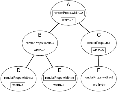
Also, if a CompositeProperty is set to null within a particular node, then the inheritance of its subproperties passes straight through that node as though the property was not defined there at all. For example, in Figure 1.2, renderProps is set to null in node C, and so renderProps.width in node F inherits its value directly from node A.
Composite property inheritance is fully supported if an inheritable property’s set accessor invokes PropertyUtils.updateCompositeProperty as shown in the code example at the end of Section 1.4.2.
Chapter 2 Rendering
2.1 Overview
This chapter describes the maspack rendering package (maspack.render), which provides a general interface for the graphical rendering of objects and allows them to implement their own rendering methods. An object makes itself renderable by implementing the IsRenderable interface, and renderable objects can then be displayed by a Viewer, which typically provides features such as viewpoint control, lighting arrangements, fixtures such as coordinate axes, grids and clipping planes, and component selection. The viewer also implements a Renderer interface which provides the actual graphics functionality which renderable objects use to draw themselves.
2.1.1 Renderables and Viewers
Any object to be rendered should implement the IsRenderable interface, which defines the following four methods,
prerender() is called prior to rendering and allows the object to update internal rendering information and possibly give the viewer additional objects to render by placing them on the RenderList (Section 2.2.2). render() is the main method by which an object renders itself, using the functionality provided by the supplied Renderer. updateBounds() provides bounds information for the renderable’s spatial extent (which the viewer can use to auto-size the rendering volume); Vector3d describes a 3-vector and is defined in the package maspack.matrix. getRenderHints() returns flags giving additional information about rendering requirements, including whether the renderable is transparent (IsRenderable.TRANSPARENT) or two dimensional (IsRenderable.TWO_DIMENSIONAL).
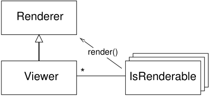
A Viewer provides the machinery needed to display renderable objects, and implements the Renderer interface (Section 2.3) with which renderables draw themselves within their render() methods. Renderer includes methods for maintaining graphics state, drawing primitives such as points, lines, and triangles, and drawing simple solid shapes. The general relationship between viewers, renderables, and renderers is shown in Figure 2.1. Rendering is triggered within a viewer by calling its rerender() method, which causes the prerender() and render() methods to be called for every renderable, as discussed in detail in Section 2.2.
2.1.2 A Complete Example
Listing 1 shows a complete example of a renderable object being declared and displayed in a viewer.
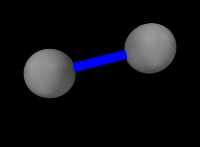
The example creates a class called RenderableExample which
implements isRenderable and the associated methods: prerender(), which does nothing; render(), which draws two gray
spheres connected by a blue cylinder; updateBounds(), which sets
the maximum and minimum bounds to be the points ![]() and
and ![]() , and getRenderHints() which returns no flags. The example
then defines a main() method which creates an instance of RenderableExample, along with a GLViewerFrame which contains a
viewer with which to display it. The renderable is added to the
viewer, the viewpoint is set so that the
, and getRenderHints() which returns no flags. The example
then defines a main() method which creates an instance of RenderableExample, along with a GLViewerFrame which contains a
viewer with which to display it. The renderable is added to the
viewer, the viewpoint is set so that the ![]() and
and ![]() axes of the
viewing plane are aligned with the world
axes of the
viewing plane are aligned with the world ![]() and
and ![]() axes, and the
frame is set to be visible, with the result shown in Figure
2.2.
axes, and the
frame is set to be visible, with the result shown in Figure
2.2.
2.2 Viewers
This section summarizes viewer functionality as defined by the Viewer interface. Note that specific viewer implementations may provide significant additional functionality, such as interactive view control, keyboard and mouse event handling, or graphical fixtures such as coordinate axes, grids or transformers. The description of these extra features is beyond the scope of this document.
Rendering is triggered within a viewer by calling its rerender() method, which then initiates two rendering steps:
-
1.
prerendering: The viewer calls the prerender() method for all its renderables, and adds those which are visible into a render list;
-
2.
repainting: All components in the render list are redrawn using their render() method;
Another viewer method, repaint(), can subsequently be called to initiate repainting without invoking prerendering.
In general, rerender() should be called whenever there is a change in the graphical state of the renderables. This includes changes in geometry, color, or visibility. In the context of simulation, rerender() should be called after every simulation step.
Otherwise, repaint() should be called when the graphical state of the scene has not changed but the final screen display has, such as when the viewpoint is changed, or the display window is unhidden or resized. This is more efficient than calling rerender() because it avoids the overhead of the prerendering step.
The prerendering step is invoked directly within the rerender() method, whereas the repainting step is called in whatever thread implements the graphical display. Since, as described below, one of the functions of the prerendering step is to cache rendering information, rerender() should be called in synchronization with both the graphical display thread and whatever thread(s) (such as a simulation thread) might be altering the state of the renderables.
2.2.1 Render lists
A render list is implemented by the class RenderList and sorts renderable components into separate sublists depending on whether they are primarily opaque, transparent, 2d opaque, and 2d transparent. These designations are determined by examining the flags returned by the renderable’s getRenderHints() method, with TWO_DIMENSIONAL indicating a two dimensional component and TRANSPARENT indicating a transparent one. These sublists assist the viewer in rendering a scene more realistically. For example, in OpenGL, better results are obtained if opaque objects are drawn before transparent ones, and two dimensional objects are drawn after three dimensional ones, with the depth buffer disabled.
A viewer maintains its own internal render list, and rebuilds it once during every prerendering step, using the following algorithm:
The list’s addIfVisible() method calls the component’s prerender() method, and then adds it to the appropriate sublist if it is visible:
A renderable’s visibility is determined as follows:
-
•
Any object implementing IsRenderable is visible by default.
-
•
If the object also implements HasRenderProps (as described in Section 2.3.9), then it is visible only if the RenderProps returned by getRenderProps() is non-null and the associated visible property is true.
As discussed in Section 2.2.3, a viewer can also be provided with an external render list, which is maintained by the application. It is the responsbility of the application, and not the viewer, to rebuild the external render list during the prerendering step. However, in the repainting step, the viewer will handle the redrawing of all the components in both its internal and external render lists.
2.2.2 Prerendering and Rendering
Prerendering allows renderables to
-
1.
update data structures anc cached data needed for rendering
-
2.
add additional renderables to the render list.
The caching of graphical state is typically necessary when rendering is performed in a thread separate from the main application, which can otherwise cause synchronization and consistency problems for renderables which are changing dynamically. For example, suppose we are simulating the motion of two objects, A and B, and we wish to render their positions at a particular time t. If the render thread is allowed to run in parallel with the thread computing the simulation, then A and B might be drawn with positions corresponding to different times (or worse, positions which are indeterminate!).
Synchronizing the rendering and simulation threads will aleviate this problem, but that means foregoing the speed improvement of allowing the rendering to run in parallel. Instead, renderables can use the prerender() method to cache their current state for later use in the render() method, in a manner analagous to double buffering. For example, suppose a renderable describes the position of a point in space, inside a member variable called myPos. Then its prerender() method can be constructed to save this into another another member variable myRenderPos for later use in render():
In the example above, the cached value is stored using floating point values, since this saves space and usually provides sufficient precision for rendering purposes.
As described in Section 2.4, objects can sometimes make use of render objects when rendering themselves. These can result in improved graphical efficieny, and also provide an alternate means for caching graphical information. If render objects are being used, it is recommmended that they be created or updated within prerender().
The prerender() method can also be used to add additional renderables to the render list. This is done by recursively calling the list’s addIfVisible() method. For example, if a renderable has two subcomponents, A and B, which also need to be rendered, then it can add them to the render list as follows:
In addition to adding A and B to the render list if they are visible, addIfVisible() will also call their prerender() methods, which will in turn give them the opportunity to add their own sub components to the render list. Note that prerender() is always called for the specified renderable, whether it is visible (and added to the list) or not (since even if a renderable is not visible, it might have subcomponents which are). This allows an entire hierarchy of renderables to be rendered by simply adding the root renderable to the viewer.
Note that any renderables added to the render list within prerender() are not added to the primary list of renderables maintained by the viewer.
Because of the functionality outlined above, calls to prerender() methods, and the viewer rerender() method that invokes them, should be synchronized with both the graphical display thread and whatever thread(s) might be altering the state of the renderables.
As indicated above, actual object rendering is done within its render() method, which is called during the repaint step, within whatever thread is responsible for graphical display. The render() method signature,
provides a Renderer interface (Section 2.3) which the object uses to draws itself, along with a flags argument that specifies additional rendering conditions. Currently only one flag is formally supported, Renderer.HIGHLIGHT, which requests that the object be rendered using highlighting (see Section 2.3.3.1).
2.2.3 Viewer renderables and external render lists
Renderables can be added or removed from a viewer using the methods
If renderables are arranged in a hierarchy, and add their own subcomponents to the render list during prerender(), as described in Section 2.2.2, then it may only be necessary to add top level renderable components to the viewer.
It is also possible to assign a viewer an external render list, for which the prerendering step is maintained by the application. This is useful in situations where multiple viewers are being used to simultaneously render a common set of renderables. In such cases, it would be wasteful for each viewer to repeatedly execute the prerender phase on the same renderable set. It may also lead to inconsistent results, if the state of renderables changes between different viewers’ invocation of the prerender phase.
To avoid this problem, an application may create its own render list and then give it to multiple viewers using setExternalRenderList(). A code sample for this is as follows:
The statement synchronize(extlist) ensures that calls to extlist.addIfVisible(r) (and the subsequent internal calls to prerender()) are synchronized with render() method calls made by the viewer. This works because the viewer also wraps its usage of extlist inside synchronize(extlist) statements.
Once the viewers have been assigned an external render list, they will handle the repainting step for its renderables, along with their own internal renderables, every time repainting is invoked through a call to either rerender() (as in the above example) or repaint().
2.2.4 Coordinate frames and view point control
A viewer maintains three primary coordinate frames for describing the relative locations and orientations of scene objects and the observing “eye” (or camera). These are the eye, model, and world frames.
The eye frame (sometimes also known as the camera frame) is a
right-handed frame located at the eye (or camera) focal point, with
the ![]() axis pointing toward the observer. The viewing frustum
is located in the half space associated with the negative
axis pointing toward the observer. The viewing frustum
is located in the half space associated with the negative ![]() axis of
the eye frame (and usually centered on said axis), with the near and
far clipping planes designated as the view plane and far
plane, respectively. The viewer also maintains a viewing center, typically located along the negative
axis of
the eye frame (and usually centered on said axis), with the near and
far clipping planes designated as the view plane and far
plane, respectively. The viewer also maintains a viewing center, typically located along the negative ![]() axis, and which
defines the point about which the camera pivots in response to
interactive view rotation.
axis, and which
defines the point about which the camera pivots in response to
interactive view rotation.
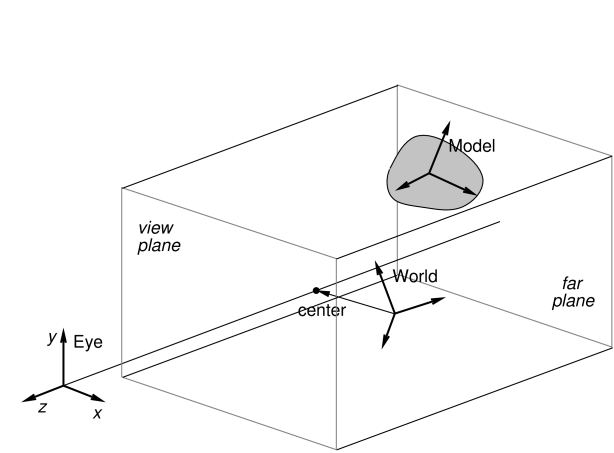
The viewing frustum is defined by the view and far planes, in combination with a projection matrix that transforms eye coordinates into clip coordinates. Most commonly, the projection matrix is set up for perspective viewing (Figure 2.3), but orthographic viewing (Figure 2.4) is sometimes used as well.
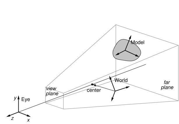
The model frame is the coordinate frame in which geometric
information for rendered objects is specified, and the world frame is the
base with respect to which the model and eye frames are defined. The
model matrix is the ![]() homogeneous affine transform
homogeneous affine transform
![]() from model to world coordinates, while the view matrix
is a
from model to world coordinates, while the view matrix
is a ![]() homogeneous rigid transform
homogeneous rigid transform ![]() from world to eye
coordinates. The composition of
from world to eye
coordinates. The composition of ![]() and
and ![]() transforms a
point from model coordinates
transforms a
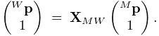
point from model coordinates ![]() into eye coordinates
into eye coordinates ![]() ,
according to:
,
according to:
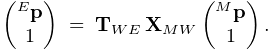 |
Note: the renderer assumes that points and vectors are column-based and the coordinate transforms work by pre-multiplying these column vectors. This is in constrast to some computer graphics conventions in which vectors are row based. Our transformation matrices are therefore the transpose of those defined with respect to a row-based convention.
Initially the world and model frames are coincident, so that ![]() . Rendering methods often redefine the model matrix, allowing
existing object geometry or built-in drawing methods to be used at
different scales and poses throughout the scene. The methods
available for querying and controlling the model matrix are described
in Section 2.3.8.
. Rendering methods often redefine the model matrix, allowing
existing object geometry or built-in drawing methods to be used at
different scales and poses throughout the scene. The methods
available for querying and controlling the model matrix are described
in Section 2.3.8.

Meanwhile, changing the view matrix allows the scene to be observed from different view points. A viewer provides the following direct methods for setting and querying the view matrix:
where
RigidTransform3d is defined
in maspack.matrix and represents a ![]() homogenous
rigid transformation.
Instead of specifying the view matrix, it is sometimes more convenient
to specify its inverse, the eye-to-world transform
homogenous
rigid transformation.
Instead of specifying the view matrix, it is sometimes more convenient
to specify its inverse, the eye-to-world transform ![]() .
This can be done with
.
This can be done with
where
Point3d and
Vector3d are also defined in
maspack.matrix and represent 3 dimensional points and vectors.
The method
setEyeToWorld(eye,center,up) sets ![]() according to legacy
OpenGL conventions so that (with respect to world coordinates) the eye
frame’s origin is defined by the point eye, while its
orientation is defined such that the
according to legacy
OpenGL conventions so that (with respect to world coordinates) the eye
frame’s origin is defined by the point eye, while its
orientation is defined such that the ![]() axis points from eye
to center and the
axis points from eye
to center and the ![]() axis is parallel to up (see Figure
2.5).
axis is parallel to up (see Figure
2.5).
Point3d is a subclass of Vector3d used to describe points in space. The only difference between the two is that they transform differently in response to rigid transforms (described by RigidTransform3d) or affine transforms (described by AffineTransform3d): point transformations include the translational component, while vector transformations do not.
The viewer also maintains a center position and an up
vector that are used to modify ![]() in conjunction
with the following:
in conjunction
with the following:
Again with respect to world coordinates, setEye(eye) sets the origin of the eye frame while recomputing its orientation from the current values of center and up, while setCenter(center) and setUpVector(up) set center and up and recompute the eye frame’s orientation accordingly.
It is also possible to specify axis-aligned views, so that the axes of the eye frame are exactly aligned with the axes of the world frame. This can be done using
setAxialView() sets the rotational
component of ![]() to REW, and moves the eye position so
that the viewer’s center lies along the new
to REW, and moves the eye position so
that the viewer’s center lies along the new ![]() axis. It also
sets the up vector to the
axis. It also
sets the up vector to the ![]() axis of REW, and stores REW as the viewer’s nominal axial view which can be used for
determining default orientations for fixtures such as grids.
AxisAlignedRotation defines 24 possible
axis-aligned orientations, and so there are 24 possible axis-aligned
views. Some of those commonly used in association with setAxialView() are:
axis of REW, and stores REW as the viewer’s nominal axial view which can be used for
determining default orientations for fixtures such as grids.
AxisAlignedRotation defines 24 possible
axis-aligned orientations, and so there are 24 possible axis-aligned
views. Some of those commonly used in association with setAxialView() are:
| X_Y | eye frame and world frame have the same orientaion |
|---|---|
| X_Z | eye frame |
| Y_Z | eye frame |
There are several methods available to reset the viewing frustum:
The setPerspective methods create a perspective-based frustum
(Figure 2.3). The first methods explicitly sets
the left, right, bottom and top edges of the view plane, along with
the (positive) distances to the near (i.e., view) and far planes,
while the second method creates a frustum centered on the ![]() axis,
using a specified vertical field of view. The setOrthogonal
methods create an orthographic frustum (Figure 2.4)
in a similar manner.
axis,
using a specified vertical field of view. The setOrthogonal
methods create an orthographic frustum (Figure 2.4)
in a similar manner.
Information about the current frustum can be queried using
For convenience, the viewer can also automatically determine appropriate values for the center and eye positions, and then fit a suitable viewing frustum around the scene. This is done using the renderables’ updateBounds() method to estimate a scene center and radius, along with the current value of the up vector to orient the eye frame. The auto-fitting methods are:
These auto-fit methods also make use of a default vertical field-of-view, which is initially 35 degrees and which can be controlled using
Finally, the viewer’s background color can be controlled using
2.2.5 Lights
Viewers also maintain scene lighting. Typically, a viewer will be initialized to a default set of lights, which can then be adjusted by the application. The existing light set can be queried using the methods
where Light is a class
containing parameters for the light.
Lights are described using the same parameters as those of OpenGL,
as described in Chapter 5 of the OpenGL Programming Guide (Red book).
Each has a position ![]() and (unit) direction
and (unit) direction ![]() in space, a type, colors associated with ambient, specular and diffuse lighting,
and coefficients for its attenuation formula. The attenuation formula
is
in space, a type, colors associated with ambient, specular and diffuse lighting,
and coefficients for its attenuation formula. The attenuation formula
is
where ![]() is the light intensity,
is the light intensity, ![]() is the distance between the
light and the point being lit, and
is the distance between the
light and the point being lit, and ![]() ,
, ![]() , and
, and ![]() are the constant,
linear and quadratic attentuation factors.
are the constant,
linear and quadratic attentuation factors.
Spot lights have the same properties as other lights, in addition to
also having a cutoff angle ![]() and an exponent
and an exponent ![]() .
The cutoff angle is the angle between the direction of the light and
the edge of its cone, while the exponent, whose default value is 0, is
used to determine how focused the light is. If
.
The cutoff angle is the angle between the direction of the light and
the edge of its cone, while the exponent, whose default value is 0, is
used to determine how focused the light is. If ![]() is the unit
direction from the light to the point being lit, and if
is the unit
direction from the light to the point being lit, and if ![]() , then the point being lit is within
the light cone and the light intensity
, then the point being lit is within
the light cone and the light intensity ![]() in the above equation is
multiplied by the spotlight effect, given by
in the above equation is
multiplied by the spotlight effect, given by
Since ![]() , a value of
, a value of ![]() gives
the least light reductuon, while valuse of
gives
the least light reductuon, while valuse of ![]() increase the
intensity of the spot light towards its center.
increase the
intensity of the spot light towards its center.
Information for a specific light is provided by a Light object, which contains the following fields:
- enabled
-
A boolean describing whether or not the light is enabled.
- type
-
An instance of Light.LightType describing the type of the light. Current values are DIRECTIONAL, POINT, and SPOT.
- position
-
A 3-vector giving the position of the light in world coordinates.
- direction
-
A 3-vector giving the direction of the light in world coordinates.
- ambient
-
RGBA values for the ambient light color.
- diffuse
-
RGBA values for the diffuse light color.
- specular
-
RGBA values for the specular light color.
- constantAttenuation
-
Constant term C in the attenuation formula
- linearAttenuation
-
Linear term L in the attenuation formula
- quadraticAttenuation
-
Quadratic term Q in the attenuation formula
- spotCosCutoff
-
For spotlights, the cosine of the cutoff angle
 .
. - spotExponent
-
For spotlights, the exponent
 .
.
Each of these fields is associated with accessor methods inside Light.
An application can also add or remove lights using
To create a new light, the application instantiates a Light object, sets the appropriate fields, and then calls addLight(). Lights can be removed either by reference to the light object or its index.
Lights are updated by the viewer at the beginning of each repaint step. That means that for lights already added to the viewer, any changes made to the fields of the associated Light object will take effect at the beginning of the next repaint step.
2.3 The Renderer Interface
This section describes the Renderer interface, which supplies the methods which objects can use to draw themselves. This includes methods for setting graphics state, and drawing point, line and triangle primitives as well as simple solid shapes.
2.3.1 Drawing single points and lines
The most basic Renderer methods provide for the drawing of single points, lines, and triangles. The following can be used to draw a pixel-based point at a specified location pnt, or a pixel-based line segment between two points pnt0 and pnt1:
where, as mentioned earlier, Vector3d represents a 3-vector and is defined in maspack.matrix.
Note: while convenient for drawing small numbers of points and lines, the methods described in this section can be quite inefficient. For rendering larger numbers of primitives, one should use either the draw mode methods of Section 2.3.4, or the even more efficient render objects described in Section 2.4.
The size of the points or lines (in pixels) can be controlled via following methods:
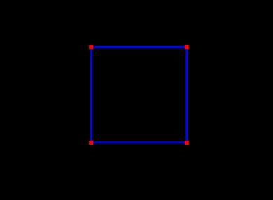
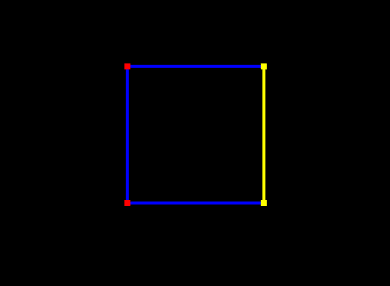
The following example draws a square in the x-z plane, with blue edges and red corners:
In addition to the draw methods described above, we use setShading() to disable and restore lighting (Section 2.3.6), and setColor() to set the point and edge colors (Section 2.3.3). It is generally necessary to disable lighting when drawing pixel-based points and lines which do not (as in this example) contain normal information. The result is shown in Figure 2.6.
For visualization and selection purposes, it is also possible to draw points and lines as solid spheres and cylinders; see the description of this in Section 2.3.1.
2.3.2 Drawing single triangles
Another pair of methods are available for drawing solid triangles:
Each of these draws a single triangle, with a normal computed automatically with respect to the counter-clockwise orientation of the vertices.
Note: as with drawing single points and lines, the single triangle methods are inefficient. For rendering large numbers of triangles, one should use either the draw mode methods of Section 2.3.4, or the render objects described in Section 2.4.
When drawing triangles, the renderer can be asked to draw the front face, back face, or both faces. The methods to control this are:
where FaceStyle is an enumerated type of Renderer with the possible values:
- FRONT:
-
Draw the front face
- BACK:
-
Draw the back face
- FRONT_AND_BACK:
-
Draw both faces
- NONE:
-
Draw neither face
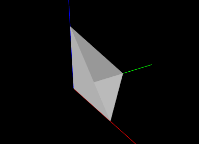
The example below draws a simple open tetrahedron with one face missing:
The result is drawn using the renderer’s default gray color, as seen in Figure 2.7.
2.3.3 Colors and associated attributes
The renderer maintains a set of attributes for controlling the color,
reflectance and emission characteristics of whatever primitives or
shapes are currently being drawn. Color values are stored as RGBA
(red, green, blue, alpha) or RGB (red, green, blue) values in the
range ![]() . The attributes closely follow the OpenGL model for
lighting materials and include:
. The attributes closely follow the OpenGL model for
lighting materials and include:
- Front color:
-
Specifies the reflected RGBA values for diffuse and ambient lighting. The default value is opaque gray:
 .
. - Back color:
-
Optional attribute, which, if not null, specifies the reflected RGBA values for diffuse and ambient lighting for back faces only. Otherwise, the front color is used. The default value is null.
- Specular:
-
Specifies the reflected RGB values for specular lighting. The default value is
 .
. - Emission:
-
Specifies the RGB values for emitted light. The default value is
 .
. - Shininess:
-
Specifies the specular exponent of the lighting equation, in the range
![[0,128]](mi/mi84.png) . The default value is 32.
. The default value is 32.
The resulting appearance of subsequently rendered primitives or shapes depends on the values of these attributes along with the shading settings (Section 2.3.6). When lighting is disabled (by calling setShading(Shading.NONE)), then rendering is done in a uniform color using only the front color (diffuse/ambient) attribute.
The primary methods for setting the color attributes are:
where rgba and rgb are arrays of length 4 or 3 that provide the required RGBA or RGB values. The rgba arguments may also have a length of 3, in which case an alpha value of 1.0 is assumed. For setBackColor(), rgba may also be null, which will cause the back color to be cleared.
Most commonly, there is no difference between the desired front and back colors, in which case one can simply use the various setColor methods instead:
These take RGB or RGBA values and set the front color, while at the same time clearing the back color, so that the front color is automatically applied to back faces. The method setFrontAlpha() independently sets the alpha value for the front color.
To query the color attributes, one may use:
The first four of these return the relevant RGBA or RGB values as an array of floats. Applications may supply the float arrays using the arguments rgba or rgb; otherwise, if these arguments are null, the necessary float arrays will be allocated. If no back color is set, then getBackColor() will return null.
2.3.3.1 Highlighting
The renderer supports the notion of highlighting, which allows the application to indicate to the renderer that subsequently rendered components should be drawn in a highlighted manner. This is typically used to show (visually) that they are selected in some way.
The highlighting style used by the renderer can be queried using the method
At present, only two values of HighlightStyle are supported:
- COLOR:
-
Highlighting is done by rendering with a distinct color.
- NONE:
-
Highlighting is disabled.
The color used for color-based highlighting can be queried using
To enable or disable highlighting, the application can use the methods
As an illustration, we alter the square drawing example of Section 2.3.1 to highlight the corners corresponding to points p1 and p1, as well as the edge between p1 and p1:
The result, assuming a highlight style of HighlightStyle.COLOR and a yellow highlight color, is shown in Figure 2.8.
2.3.4 Drawing using draw mode
For convenience, the renderer provides a draw mode in which primitive sets consisting of points, lines and triangles can be assembled by specifying a sequence of vertices and (if necessary) normals, colors, and/or texture coordinates between calls to beginDraw(mode) and endDraw(). Because draw mode allows vertex and normal information to be collected together and sent to the GPU all at one time (when endDraw() is called), it can be significantly more efficient than the single point, line and triangle methods described in the previous sections. (However, using render objects can be even more efficient, as described in Section 2.4.)
| DrawMode | Description | Equivalent OpenGL Mode |
|---|---|---|
| POINTS | A set of independent points | GL_POINTS |
| LINES | A set of line segments, with two vertices per segment | GL_LINES |
| LINE_STRIP | A line strip connecting the vertices in order | GL_LINE_STRIP |
| LINE_LOOP | A line loop connecting the vertices in order | GL_LINE_LOOP |
| TRIANGLES | A set of triangles, with three vertices per triangle | GL_TRIANGLES |
| TRIANGLE_STRIP | A triangle strip | GL_TRIANGLE_STRIP |
| TRIANGLE_FAN | A triangle fan | GL_TRIANGLE_FAN |
Draw mode is closely analgous to immediate mode in older OpenGL specifications. The types of primitive sets that may be formed from the vertices are defined by Renderer.DrawMode and summarized in Table 2.1. The primitive type is specified by the mode argument of the beginDraw(mode) call that initiates draw mode.
Between calls to beginDraw(mode) and endDraw(), vertices may be added using the methods
each of which creates and adds a single vertex for the specified point. Normals may be specified using
It is not necessary to specify a normal for each vertex. Instead, the first setNormal call will specify the normal for all vertices defined to that point, and all subsequent vertices until the next setNormal call. If no setNormal call is made while in draw mode, then the vertices will not be associated with any normals, which typically means that the primitives will be rendered as black unless lighting is disabled (Section 2.3.6).
It is also possible to specify per-vertex colors during draw mode. This can be done by calling any of the methods of Section 2.3.3 that cause the front color to be set. The indicated front color will then be assigned to vertices defined up to that point, and all subsequent vertices until the next call that sets the front color. The primitives will then be rendered using vertex coloring, in which the vertex color values are interpolated to determine the color at any given point in a primitive. This color overrides the current front (or back) color value (or mixes with it; see Section 2.3.7). If vertex colors are not specified, then the primitives will be rendered using the color attributes that were in effect when draw mode was first entered.
Finally, per-vertex texture coordinates can be specified within draw mode. The methods for doing this are analagous to those for setting normals,
where Vector2d is defined in maspack.matrix. Texture coordinates are required for any rendering that involves texture mapping, including color, normal or bump maps (Section 2.5).
When draw mode is exited by calling endDraw(), the specified vertices, along with any normal, color or texture information, is sent to the GPU and rendered as the specified primitive set, using the current settings for shading, point size, line width, etc.
As an example, the code below uses draw mode to implement the square drawing of Section 2.3.1 (which is shown in Figure 2.6):
Note that no normals need to be specified since both primitive sets are rendered with lighting disabled.
Another example uses draw mode to implement the partial tetrahedron example from Section 2.3.2 (which is shown in Figure 2.7):
Note that because for this example we are displaying shaded faces, it is necessary to specify a normal for each triangle.
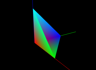
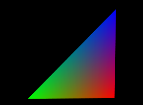
As a final example, we show the tetrahedon example again, but this time with colors specified for each vertex, which initiates vertex coloring. Vertices p0, p1, p2, and p3 are associated with the colors RED, GREEN, BLUE, and CYAN, respectively. The corresponding code looks like this:
and the rendered result is shown in Figure 2.9.
2.3.5 Drawing solid shapes
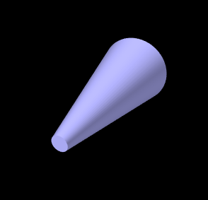
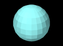
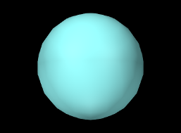
For convenience, the renderer provides a number of methods for drawing solid shapes. These include spheres, cylinders, cubes, boxes, arrows, spindles, cones, and coordinate axes.
Methods for drawing spheres include
both of which draw a sphere with radius rad centered at the point pnt, using the current color and shading settings. For drawing cylinders, arrows, or spindles, one can use
each of which draws the indicated shape between points pnt0 and pnt1 with a cylindrical radius of rad, again using the current color and shading. The argument capped for cylinders and arrows indicates whether or not a solid cap should be drawn over any otherwise open ends. For arrows, the arrow head size is based on the radius and line segment length. Another method,
draws an arrow starting at pnt and extending in the direction dir, with a length given by the length of dir times scale.
A cone can be drawn similarly to a cylinder, using
with the only difference being that there are now two radii, rad0 and rad1, at each end.
 |
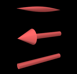 |
 |
To draw cubes and boxes, one may use
The drawCube methods draw an axis-aligned cube with a specified width centered on the point pnt. Similarly, the first two drawBox methods draw an axis-aligned box with the indicated x, y, and z widths. Finally, the last drawBox method draws a box centered on, and aligned with, the coordinate frame defined (with respect to model coordinates) by the RigidTransform3d TBM.
When rendering the curved solids described above, the renderer must create surface meshes that approximate their shapes. The resolution used for doing this can be controlled using a parameter called the surface resolution. This is defined to be the number of line segments that would be used to approximate a circle, and this level of resolution is then employed to create the mesh. The renderer initializes this parameter to a reasonable default value, but applications can query or modify it as needed using the following methods:
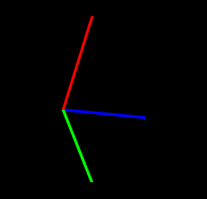
Coordinate axes can be drawn to show the position and orientation of a spatial coordinate frame:
For these, the coordinate frame is described (with respect to the current
model coordinates) by a
RigidTransform3d T. The first method
draws the frame’s axes
as lines with the specified length len and width. The second method allows different lengths (lens) to be
specified for each axis. The axis lines are rendered using regular
pixel-based lines with non-shaded colors, with the ![]() ,
, ![]() , and
, and ![]() axes normally being colored red, green, and blue.
However, if highlight is true and the highlight
style is
HighlightStyle.COLOR
(Section 2.3.3.1), then all axes are drawn
using the using the highlight color.
axes normally being colored red, green, and blue.
However, if highlight is true and the highlight
style is
HighlightStyle.COLOR
(Section 2.3.3.1), then all axes are drawn
using the using the highlight color.
Some of the solids are illustrated in Figure 2.10.
2.3.6 Shading and color mixing
Shading determines the coloring of each rendering primitive (point, line or triangle), as seen from the eye, as a result of its color attributes, surface normals and the current lighting conditions. At any given point on a primitive, the rendered color is the coloring seen from the eye that results from the incident illumination, color attributes, and surface normal at that point. In general, the rendered color varies across the primitive. How this variation is handled depends on the shading, defined by Renderer.Shading:
- FLAT:
-
The rendered color is determined at the first vertex and applied to the entire primitive. This makes it easy to see the individual primitives, which can be desirable under some circumstances. Only one normal needs to be specified per primitive.
- SMOOTH:
-
Rendered colors are computed across the primitive, based on interpolated normal information, resulting in a smooth appearance. The interpolation technique depends on the renderer. OpenGL 2 implementations use Gouraud shading, while the OpenGL 3 renderer uses Phong shading.
- METAL:
-
Rendered colors are computed using a smooth shading technique that may be more appropriate to metalic objects. For some renderer implementations, there may be no difference between METAL and SMOOTH.
- NONE:
-
Lighting is disabled. The rendered color becomes the diffuse color, which is applied uniformly across the primitive. No normals need to be specified.
 |
 |
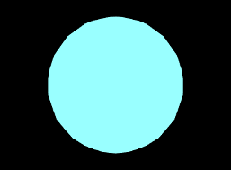 |
Figure 2.11 shows different shading methods applied to a sphere.
The shading can be controlled and queried using the following methods,
where setShading() returns the previous shading setting.
Lighting is often disabled, using Shading.NONE, when rendering pixel-based points and lines. That’s because normal information is not naturally defined for these primitives, and also because even if normal information were to be provided, shading could make them either invisible or hard to see from certain viewing angles.
2.3.7 Vertex coloring, and color mixing and interpolation
As mentioned in Section 2.3.4, it is possible to specify vertex coloring for a primtive, in which vertex color values are interpolated to determine the color at any given point in the primitive. Vertex colors can be specified by calling setColor primitives while in draw mode. They can also be specified as part of a RenderObject (Section 2.4).
When vertex coloring is used, the interpolated vertex colors either replace or are combined with the current front (or back) diffuse color at each point in the primitive. Other color attributes, such as emission and specular, are unchanged. If lighting is disabled, then the rendered color is simply set to the resulting vertex/diffuse color combination.
Whether the vertex color replaces or combines with the underlying diffuse color is controlled by the enumerated type Renderer.ColorMixing, which has four different values:
| REPLACE | replace the diffuse color (default behavior) |
| MODULATE | multiplicatively combine with the diffuse color |
| DECAL | combine with the diffuse color based on the latter’s alpha value |
| NONE | diffuse color is unchanged (vertex colors are ignored) |
 |
 |
 |
Color mixing can be controlled using these methods:
A given Renderer implementation may not support all color mixing modes, and so the hasVertexColorMixing() can be used to query if a given mixing mode is supported. The OpenGL 2 renderer implementation does not support MODULATE or DECAL. Some examples of vertex coloring with different shading and color mixing settings are shown in Figure 2.12.
The renderer’s default color mixing mode is MODULATE. This has the advantage of allowing rendered objects to still appear differently when highlighting is enabled and the highlight style is HighlightStyle.COLOR (Section 2.3.3.1), since the highlight color is combined with the vertex color rather than being replaced by it.
 |
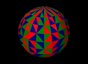 |
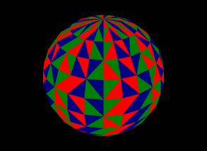
Vertex coloring can be used in different ways. Assigning different colors to the vertices of a primitive will result in a blending of those colors within the primitive (Figures 2.9 and 2.12). Assigning the same colors to the vertices of a primitive can be used to give each primitive a uniform color. Figure 2.13 shows vertex coloring applied to the same sphere as Figures 2.3.6 and 2.12, only with the vertices for each face being uniformly set to red, green or blue, resulting in uniformly colored faces.
 |
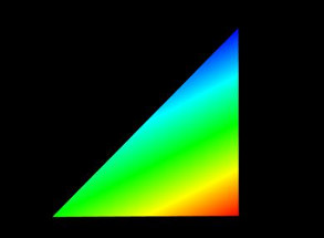 |
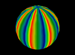
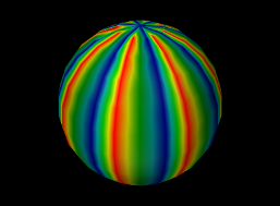
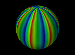
When using vertex coloring, the interpolation of colors across the primitive can be done either in RBG or HSV space. HSV stands for hue, saturation, and value (or brightness), and it is often the best interpolation method to use when the vertex colors have a uniform brightness that the interpolation should preserve. This leads to a “rainbow” look that is common in situations like color-based stress plots. Figure 2.14 illustrates the difference between RGB and HSV interpolation.
Color interpolation is specified with the enumerated type Renderer.ColorInterpolation, which currently has the two values RGB and HSV. Within the renderer, it can be controlled using the methods
2.3.8 Changing the model matrix
When point positions are specified to the renderer, either as the arguments to various draw methods, or for specifying vertex locations in draw mode, the positions are assumed to be defined with respect to the current model coordinate frame. As described in Section 2.2.4, this is one of the three primary coordinate frames associated with the viewer, with the other two being the world and eye frames.
The relationship between model and world frames is controlled by the
model matrix ![]() , which is a
, which is a ![]() homogeneous
affine transform that transforms points in model coordinates (denoted
by
homogeneous
affine transform that transforms points in model coordinates (denoted
by ![]() ) to world coordinates (denoted by
) to world coordinates (denoted by ![]() ), according to
), according to
 |
Initially the world and model frames are coincident, so that ![]() . Rendering methods often redefine the model matrix, allowing
object geometry to be specified in a conveniently defined local
coordinate frame, and, more critically, allowing the predefined
geometry associated with existing rendering objects (Section
2.4) or built-in drawing methods to be used at
different scales and poses throughout the scene. Methods for querying
and controlling the model matrix include:
. Rendering methods often redefine the model matrix, allowing
object geometry to be specified in a conveniently defined local
coordinate frame, and, more critically, allowing the predefined
geometry associated with existing rendering objects (Section
2.4) or built-in drawing methods to be used at
different scales and poses throughout the scene. Methods for querying
and controlling the model matrix include:
Both getModelMatrix() and
getModelMatrix(XMW) return the current model matrix value (where the
value returned by the first method should not be modified).
AffineTransform3dBase is a base class defined
in maspack.matrix and represents a ![]() homogeneous transform
that is either a rigid transform
(of type
RigidTransform3d) or an affine transform
(of type AffineTransform3d).
setModelMatrix(XMW)
explicitly sets the model matrix, while
mulModelMatrix(X)
post-multiplies the current matrix by another rigid or
affine transform
homogeneous transform
that is either a rigid transform
(of type
RigidTransform3d) or an affine transform
(of type AffineTransform3d).
setModelMatrix(XMW)
explicitly sets the model matrix, while
mulModelMatrix(X)
post-multiplies the current matrix by another rigid or
affine transform ![]() , which is equivalent to
setting
, which is equivalent to
setting
translateModelMatrix(tx,ty,tz) and
rotateModelMatrix(zdeg,ydeg,xdeg) translate or rotate the model
frame by post-multiplying the model matrix by a rigid transform
describing either a translation (tx, ty, tz), or
a rotation formed by three successive rotations: zdeg degrees
about the ![]() axis, ydeg degrees about the new
axis, ydeg degrees about the new ![]() axis, and
finally xdeg degrees about the new
axis, and
finally xdeg degrees about the new ![]() axis.
scaleModelMatrix(s)
scales the current model frame by
post multiplying the model matrix by a uniform scaling transform
axis.
scaleModelMatrix(s)
scales the current model frame by
post multiplying the model matrix by a uniform scaling transform
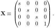 |
Finally, pushModelMatrix() and popModelMatrix() save and restore the model matrix from an internal stack. It is common to wrap changes to the model matrix inside calls to pushModelMatrix() and popModelMatrix() so that the model matrix is preserved unchanged for subsequent use elsewhere:
2.3.9 Render properties and RenderProps
The maspack.render package defines an object called RenderProps which encapsulates many of the properties that are needed to describe how an oject should be rendered. These properties control the color, size, and style of the three primary rendering primitives: faces, lines, and points, and all are exposed using the maspack.properties package, so that they can be easily set from a GUI or inherited from ancestor components.
A renderable object can maintain its own RenderProps object, and use the associated properties as it wishes to control rendering from within its render() method. Objects maintaining their own RenderProps can declare this by implementing the HasRenderProps interface, which declares the methods
It is not intended for RenderProps to encapsulate all properties relevant to the rendering of objects, but only those which are commonly encountered. Any particular renderable may still need to define and maintain more specialized rendering properties.
Renderable objects that implement both HasRenderProps and IsSelectable (an extension of IsRenderable for selectable objects described in Section 2.7) are identified by the combined interface Renderable.
2.3.9.1 Drawing points and lines as 3D solid objects
RenderProps contains two properties, pointStyle and lineStyle, that indicate whether points and lines should be drawn using standard pixel-based primitives or some type of solid 3D geometry. Often, the latter can be preferable for visualization and graphical selection. pointStyle and lineStyle are described by the enumerated types Renderer.PointStyle and Renderer.LineStyle, respectively, which contain the following entries:
| PointStyle: | |
|---|---|
| POINT | pixel-based point |
| SPHERE | solid sphere |
| CUBE | solid cube |
| LineStyle: | |
| LINE | pixel-based line |
| CYLINDER | solid cylinder |
| SOLID_ARROW | solid arrow |
| SPINDLE | spindle (an ellipsoid tapered at each end) |
The size (in pixels) for pixel-based points is controlled by the property pointSize, whereas the radius for spherical points and half-width for cubic points is controlled by pointRadius. Likewise, the width (in pixels) for pixel-based lines is controlled by lineWidth, whereas the radii for lines rendered as cylinders, arrows or spindles is controlled by lineRadius.
2.3.9.2 RenderProps taxonomy
All of the RenderProps properties are listed in table 2.2. Values for the shading, faceStyle, lineStyle and pointStyle properties are defined using the following enumerated types: Renderer.Shading, Renderer.FaceStyle, Renderer.PointStyle, and Renderer.LineStyle. Colors are specified using java.awt.Color.
| property | purpose | default value |
| visible | whether or not the component is visible | true |
| alpha | transparency for diffuse colors (range 0 to 1) | 1 (opaque) |
| lighting | lighting style: (FLAT, SMOOTH, METAL, NONE) | FLAT |
| shininess | shininess parameter (range 0 to 128) | 32 |
| specular | specular color components | null |
| faceStyle | which polygonal faces are drawn (FRONT, BACK, FRONT_AND_BACK, NONE) | FRONT |
| faceColor | diffuse color for drawing faces | GRAY |
| backColor | diffuse color used for the backs of faces. If null, faceColor is used. | null |
| drawEdges | hint that polygon edges should be drawn explicitly | false |
| colorMap | color map properties (see Section 2.5) | null |
| normalMap | normal map properties (see Section 2.5) | null |
| bumpMap | bump map properties (see Section 2.5) | null |
| edgeColor | diffuse color for edges | null |
| edgeWidth | edge width in pixels | 1 |
| lineStyle: | how lines are drawn (CYLINDER, LINE, or SPINDLE) | LINE |
| lineColor | diffuse color for lines | GRAY |
| lineWidth | width in pixels when LINE style is selected | 1 |
| lineRadius | radius when CYLINDER or SPINDLE style is selected | 1 |
| pointStyle | how points are drawn (SPHERE or POINT) | POINT |
| pointColor | diffuse color for points | GRAY |
| pointSize | point size in pixels when POINT style is selected | 1 |
| pointRadius | sphere radius when SPHERE style is selected | 1 |
In addition to colors for points, lines, and faces, there are also optional colors for edges and back faces. Edge colors (and edge widths) are provided in case an object has both lines and faces, and may want to render the edges of the faces in a color separate from the line color, particularly if drawEdges is set to true. (PolygonalMeshRenderer, described in Section 2.6, responds to drawEdges by drawing the polygonal edges using edgeColor.) Back face colors are provided so that back faces can be rendered using a different color than the front face.
Exactly how a component interprets its render properties is up to the component (and more specifically, up to the render() method for that component). Not all render properties are relevant to all components, particularly if the rendering does not use all of the rendering primitives. For example, some components may use only the point primitives and others may use only the line primitives. For this reason, some components use subclasses of RenderProps, such as PointRenderProps and LineRenderProps, that expose only a subset of the available render properties. All renderable components provide the method createRenderProps() that will create and return a RenderProps object suitable for that component.
2.3.9.3 Renderer methods that use RenderProps
Renderer provides a number of convenience methods for setting attributes and drawing primitives and shapes based on information supplied by RenderProps.
For drawing points and lines, there are
The drawPoint() methods draw a point at location pnt using the pointStyle, pointColor, pointSize, pointRadius and shading properties of props, while the drawLine methods draw a line between pnt0 and pnt1 using the lineStyle, lineColor, lineSize, lineRadius and shading properties. The second drawLine method also allows an alternate color to be specified, as well as whether or not the line shape should be capped (if appropriate). The drawRay() method draws a line starting at pnt and extending along dir, with a length equal to the length of dir times scale. Another method,
is identical to the second drawLine method above except that the line style LineStyle.SOLID_ARROW is assumed. For all methods, the highlight argument can be used to request that the primitive or shape be drawn with highlighting enabled (Section 2.3.3.1).
To draw a line strip, one can use
which draws a line strip with the specified pnts, using the indicated style along with the lineColor, lineSize, lineRadius and shading properties of props. The strip is rendered with highlighting if highlight is true.
There are also methods for setting the color attributes associated with pointColor, lineColor, edgeColor, or faceColor:
These set the renderer’s front color attribute to the value of the indicated color property, use props to also set the shininess and specular attributes, and restore emission to its default renderer value. The first three methods clear the back color attribute, while the setFace methods set it to the backColor value of props. setEdgeColoring() uses lineColor if edgeColor is null, and the second setFace method allows an alternate front color to be supplied as rgba. For all methods, highlighting is enabled or disabled based on the value of highlight. A related method is
which behaves similarly except that the color is explicitly specified using rgba.
Lastly, there are methods to set the shading:
setPointShading() sets the shading to the shading property of props and returns the previous value. setPointShading() does the same, unless pointStyle is PointStyle.POINT, in which case lighting is turned off by setting the shading to Shading.NONE. Similarly, setLineShading() turns off the lighting if lineStyle is LineStyle.LINE.
2.3.10 Screen information and 2D rendering
The screen refers to the 2 dimensional pixelized display on which the viewer ultimately renders the scene. There is a direct linear mapping between the view plane (Figure 2.2.4) and the screen.
While the renderer does not give the application control over the screen dimensions, it does allow them to be queried using
It also allows distances in pixel space to be converted to distances in world space via
distancePerPixel(p) computes the displacement distance of a point p, in a plane parallel to the view plane, that corresponds to a screen displacement of one pixel. centerDistancePerPixel() computes the same thing with p given by the center point (Section 2.2.4).
A renderer may also support 2D mode to facilitate the rendering of 2D objects directly in screen coordinates. 2D mode can be queried with the following methods:
In order for an object to be rendered in 2D, the renderable should
return the flag
IsRenderable.TWO_DIMENSIONAL from its
getRenderHints() method.
The viewer will then call the render() method in two dimensional
mode, with the view matrix set to the identity, and the projection and
model matrices set to provide an orthographic view (Figure
2.4) with the world frame located at the lower left
screen corner, the ![]() axis horizontal and pointing to the right, and
the
axis horizontal and pointing to the right, and
the ![]() axis vertical. The top right corner of the screen corresponds
to the point
axis vertical. The top right corner of the screen corresponds
to the point ![]() , where
, where ![]() and
and ![]() are the width and height of
screen returned by
getScreenWidth() and
getScreenHeight().
Lighting is also disabled and the depth buffer
is turned off, so that rendered objects will always be visible in the
order they are drawn.
are the width and height of
screen returned by
getScreenWidth() and
getScreenHeight().
Lighting is also disabled and the depth buffer
is turned off, so that rendered objects will always be visible in the
order they are drawn.
If a different scaling or origin for the x-y plane is desired, the application can call the renderer method
which will reset the model matrix so that the lower left and upper right of the screen correspond to the points (left, bottom) and (right, top), respectively.
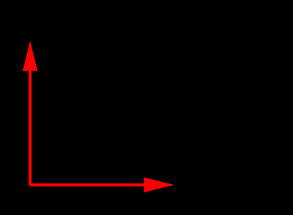
The following example shows the code for a renderable that uses 2D rendering to draw a pair of coordinate axes in the lower left screen corner, with the result shown in Figure 2.15. Its getRenderHints() method returns the TWO_DIMENSIONAL flag to ensure that render() is called in 2D mode. The axis arrowheads are drawn using the method drawArrowHead, which draws an arrowhead in a fixed location and orientation, in combination with changes to the model matrix (Section 2.2.4) to adjust the base location and orientation as required.
2.3.11 Depth offsets
Sometimes, when drawing different primitives that lie on the same plane, the depth buffer cannot properly resolve which primitive should be visible. This artifact is known as “z fighting”. The renderer provides a means to address it via the method
This modifies the projection matrix to incorporate a small offset (in
clip coordinates) along the eye frame’s ![]() axis, so that subsequently
rendered components are rendered slightly closer to (or farther from)
the eye. Each unit of offset equals one unit of depth buffer
precision. The depth offset can be queried using
getDepthOffset(), and the
default value is 0.
axis, so that subsequently
rendered components are rendered slightly closer to (or farther from)
the eye. Each unit of offset equals one unit of depth buffer
precision. The depth offset can be queried using
getDepthOffset(), and the
default value is 0.
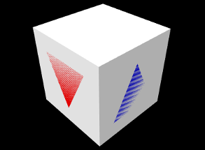 |
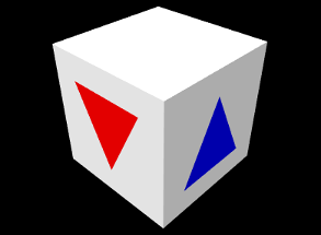 |
The listing below shows an example in which two colored triangles are drawn on faces of a cube. If no depth offset is set, the triangles compete for visibility with the underlying cube faces (Figure 2.16, left). To resolve this, the render() method sets a depth offset to move the triangles slighting closer to the eye.
z-fighting may still occur if the plane in which the fighting occurs is tilted significantly with respect to the eye. In some situations it may be desirable to mitigate this with a larger offset value.
2.3.12 Maintaining the graphics state
| Attribute | Description | Default value | Restored |
| front color | diffuse/ambient color | (0.5, 0.5, 0.5, 1.0) | no |
| back color | optional color for back faces | null | yes |
| emission | emission color | (0, 0, 0) | yes |
| specular | specular color | (0.1, 0.1, 0.1) | yes |
| shininess | specular color | 32 | yes |
| color interpolation | interpolation method for vertex colors | RGB | yes |
| face style | whether to draw front or back faces | FRONT | yes |
| line width | width of pixel-based lines | 1 | yes |
| point size | size of pixel-based points | 1 | yes |
| model matrix | transform from model to world coordinates | IDENTITY | yes |
| highlighting | highlight drawn primitives | false | yes |
| shading | primitive shading based on normal information | FLAT | yes |
| surface resolution | internal curved surface resolution | 32 | no |
| vertex color mixing | how to combine underlying and vertex colors | REPLACE | yes |
| depth offset | moves rendered objects slightly along the eye z axis | 0 | yes |
| color map | color map properties (Section 2.5) | null | yes |
| normal map | normal map properties (Section 2.5) | null | yes |
| bump map | bump map properties (Section 2.5) | null | yes |
Attributes such as colors, face styles, line widths, matrix values, etc., constitute the graphics state associated with the renderer. Table 2.3 summarizes these attributes and their default values. The last column, Restored, indicates if the renderer will restore the attribute to its default value after calling each renderable’s render() method in the repaint step. All restored attributes can therefore be assumed to be set to their default value at the beginning of any render() method when that method is being called by the renderer.
Note that in some cases, a renderable’s render() method may not be called by the render. This will occur, for instance, when a renderable takes direct control of rendering its subcomponents, and calls their render() methods directly. In such cases, it will be up to either the subcomponents or the parent to maintain the graphics state as required. There are several ways to acccomplish this.
One way is to save and restore each attribute that is modified. To facilitate this, most attribute set methods return the attribute’s previous value. Save and restore can then be done using blocks of the form
As mentioned earlier, the model matrix can be saved and restored using the following:
Alternatively, if it is sufficient to restore an attribute to its default value, one can do that directly:
Finally, the renderer method restoreDefaultState() can be used to restore that default state of all attributes except the front color:
If true, the strictChecking argument causes an exception to be thrown if the renderer is still in a draw mode block (Section 2.3.4) or the model matrix stack is not empty. restoreDefaultState() is used internally by the renderer to restore state.
2.3.13 Text rendering
Some renderer implementations provide the ability to render text objects, using fonts described by the Java class java.awt.Font. Support for text rendering can be querired using the method hasTextRendering(). The methods for drawing text include:
Each of these draws the string str in the x-y plane in model coordinates, using either a specified font or a default. The starting position of the lower left corner of the text box is given by pos, and emSize gives the size of an “em” unit. The methods return the horizontal advance distance of the draw operation.
Other supporting methods for text rendering include:
These set and query the default font, and return the bounds of a text box in a java.awt.geom.Rectangle2D.

The method setupFonts() is called outside the render method to set up some fonts and store them in the member variables myComic and mySerif. Note that setting up fonts in general may be system specific. Three different blocks of text are then drawn within the render() method, with different colors, positions and orientations. The last block consists of multiple lines, with getTextBounds() used to obtain the text bounds necessary to center each line.
Note: Rendered text is shaded in the same way as other surfaces, so unless shading is set to Shading.NONE, light must be shining on it in order for it to be visible. If you want text to always render at full intensity, shading should be set to Shading.NONE.
2.4 Render Objects
In modern graphics interfaces, applications send geometric, color, and texture information to the GPU, which then applies the various computations associated with the graphics pipeline. Transferring this data to the GPU can be an expensive activity, and efficient applications try to minimize it. Modern OpenGL, in particular, requires applications to bundle the geometric, color, and texture information into buffer objects, which are transmitted to the GPU and then cached there. This generally increases efficiency because (a) large amounts of data can be transferred at once, and (b) the cached data can be reused in subsequent rendering operations.
For OpenGL renderer implementations, a buffer object must be created and transmitted to the GPU once for every invocation of a draw method or beginDraw()/endDraw() block. As a more efficient alternative, applications can create instances of render objects, which store geometric, color, and texture information and manage the transmission of this data to the GPU. Essentially, a render object provides a convenience wrapper for OpenGL-type buffer objects. However, the use of render objects is generic and not limited to OpenGL implementations of the renderer.
Render objects are implemented using the RenderObject class, which contains:
-
•
Attribute data, including positions, and (optionally) normals, colors, and texture coordinates.
-
•
vertex data, where each vertex points to a single position, as well as (optionally) a single normal, color, and texture attribute.
-
•
primitive data, consisting of zero or more “groups” of points, lines, and triangles.
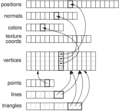
To summarize, primitives are made of vertices, which are in turn comprised of references to attributes (Figure 2.18).
Render objects can be created anywhere within the application program, although care must be taken to synchronize their modification with the render() methods. While an easy way to do this is to create them directly within the render method, care should then be taken to allow them to persist between render invocations, since each time a new object is created, all of its data must be transferred to the GPU. It is recommended to create render objects within prerender(), since this should automatically provide synchronization with both render() and any other thread this is modifying render data. A render object can itself be used to cache rendering data associated with a dynamically varying object, in which case creating (or updating) it from within the prerender method is even more appropriate.
2.4.1 Building a render object
Attributes can be added using a variety of RenderObject methods, including:
Each of these creates an instance of the specified attribute, sets it to the indicated value, adds it to the render object, and assigns it a unique index, which is returned by the add method. The index can be referred to later when adding vertices, or when later changing the attribute’s value (Section 2.4.5). Indices are increased sequentially, starting from zero.
Methods above marked “set by reference” use the supplied array to directly store values within the attribute, so that subsequent changes to the array’s values will also cause the attribute’s values to change.
A vertex is defined by a 4-tuple of indices that can be used to refer
to a previously defined instance of each of the four attributes:
position, normal, color, and texture coordinate. A vertex does not
need to reference all attributes, but it is required that all vertices have a consistent set of attributes (e.g. either all
vertices have a normal reference, or none do). When adding a vertex, a
negative index indicates that the attribute is not present. Since a
vertex can refer to at most one of each attribute, this means that
when building primitives, it may be necessary to define multiple
vertices for the same position if different values are required for
the other attributes (e.g., normals, colors, or texture coordinates).
For example, for the corner of the cube at location ![]() ,
there must be three vertices defined, one each with normals
,
there must be three vertices defined, one each with normals
![]() ,
, ![]() , and
, and ![]() .
.
Referencing attributes by index allows for attributes to be reused, and also for the numbers of any given attribute to vary. For example, when rendering the faces of a solid cube, we typically need 24 vertices (4 for each of the 6 faces), but only 8 positions (one per corner) and 6 normals (one per face).
Vertices can be added using the RenderObject method
where pidx, nidx, cidx, and tidx are the indices of the desired postion, normal, color and texture coordinate attributes (or -1 for attributes that are undefined). The method returns a unique index for the vertex, which can be referred to later when adding primitives. Indices are increased sequentially, starting from zero.
Once vertices are created, they can be used to define and add primitives. Three types of primitives are available: points (one vertex each), lines (two vertices each), and triangles (three vertices each). Methods for adding these include
Each of these takes a set of vertex indices, creates the corresponding primitive, and adds it to the current group for the that primitive (primitive groups are discussed in Section 2.4.7).
Once all the primitives have been added, the Renderer method draw(RenderObject) can then be used to draw all the primitives in the object using the current graphics state. A variety of other draw methods are available for drawing subsets of primitives; these are detailed in Section 2.4.6.
There are no methods to remove individual attributes, vertices, or primitives. However, as described in Section 2.4.5, it is possible to use clearAll() to clear the entire object, after which it may be rebuilt, or clearPrimitives() to clear just the primitive sets.
Listing 3 gives a complete example combining the above operations to create a render object that draws the open tetrahedron described in Section 2.3.2 and Figure 2.7. In this example, the object itself is created using the method createTetRenderObject(). This is in turn called once within prerender() to create the object and store it in the member field myRob, allowing it to then be used as needed within render(). As indicated above, it is generally recommended to create or update render objects within the prerender method, particularly if they need to be modfied to reflect dynamically changing geometry or colors.
2.4.2 “Current” attributes
Keeping track of attribute indices as described in Section 2.4.1 can be tedious. Instead of doing this, one can use the fact that every attribute add method records the index of the added attribute, which then denotes the “current” value for that attribute. The following methods can then be used to add a vertex using various current attribute values:
If any of the attributes have no “current” value, then the corresponding index value is -1 and that attribute will be undefined for the vertex.
If desired, it is possible to set or query the current attribute index, using methods of the form
where <Attribute> is Position, Normal, Color, or TextureCoord and idx is the index of a currently added attribute. For convenience, another set of methods,
will create a new position at the specified location, and then also create a vertex using that position along with the current normal, color and texture coords.
We now give some examples. First, Listing 4 changes the tetrahedron code in Listing 3 to use a current normal in conjuction with vertex(px, py, pz).
One issue with using vertex(px, py, pz) is that it creates a new position for every vertex, even in situations where vertices can be shared. The example above (implicitly) creates 9 positions where only 4 would be sufficient. Instead, one can create the positions separately (as in Listing 3), and then use vertex(pidx) to add vertices created from predefined positions along with current attribute values. Listing 5 does this for the tetrahedron, while also using a current color to give each face it’s own color. The rendered results are shown in Figure 2.19.
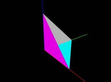
2.4.3 Maintaining consistent attributes
As mentioned earlier, all vertices within a render object must have a consistent set of attributes. That means that if some vertices are defined with normals or colors, they all must be defined with normals or colors, even if it means giving some vertices “dummy” versions of these attributes for primitives that don’t need them.
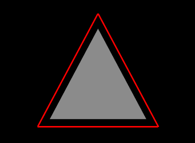
For example, suppose we wish to create an oject that draws a triangular face surrounding by an outer border (Figure 2.20). One might write the following code to create and draw the render object:
This creates a render object containing vertices for the border and triangle, along with the line and triangle primitives. Then render() first draws the border and the triangle, using the renderer’s drawLines() and drawTriangles() methods (described in Section 2.4.6). Because the border is drawn with lighting disabled, no normal is required and so its vertices are created without one. However, as written, this example will crash, because the triangle vertices do contain a normal, and therefore the border vertices must as well. The example can be fixed by moving the addNormal() call in front of the creation of the first three vertices, which will then contain a normal even though it will remain unused.
2.4.4 Adding primitives in “build” mode
The RenderObject can also be systematically constructed using a “build mode”, similar to the draw mode described in Section 2.3.4. Build mode can be invoked for any of the primitive types defined by DrawMode (Table 2.1).
Primitive construction begins with beginBuild(DrawMode) and ends with endBuild(). While in build mode, the application adds vertices using any of the methods described in the previous sections. Then, when endBuild() is called, the render object uses those those vertices to create the primitives that were specified by the mode argument of beginBuild(mode).
Listing 6 shows a complete example where build mode is used to create a RenderObject for a cylinder. In this example, we first reserve memory for the required attributes, vertices and triangles. This is not a required step, but does help with internal storage. Then, we use a triangle strip to construct the rounded sides of the cylinder, and triangle fans to construct the caps. When constructing the sides, we use vertex(px,py,pz) to create positions and vertices at the same time. Then when constucting the caps, we use addVertex(pidx) to add vertices that reuse the positions created for the sides (knowing that the position indices start at 0). The final cylinder is shown using flat shading in Figure 2.21.
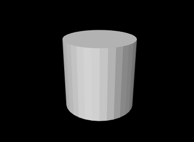
2.4.5 Modifying render objects
Sometimes, an application will build a render object once, and then never change any of its attributes, vertices, or primitives. Such objects are called static, and are the most efficient for rendering purposes since their data only needs to be transmitted to the GPU once. After the renderer first draws the object (using any of the draw methods described in Section 2.4.6), it can continue to draw a static object as many times as needed without having to send more information to the GPU. (Note however that such objects can still be repositioned within the scene by adjusting the model matrix as described in Section 2.2.4). Therefore, applications should attempt to use static render objects whenever possible.
However, often it is necessary to modify a render object. Such modifications may take three forms:
-
•
Vertex changes involving changes to the vertex structure;
-
•
Primitive changes involving changes to the primitive structure;
-
•
Attribute changes involving changes to the attribute structure or the modification of existing attribute values.
Vertex changes occur whenever new vertices are added (using any of the add methods described in the previous sections), or the entire object is cleared using clearAll(). These generally require retransmission of the vertex and attribute information to the GPU.
Primitive changes occur when new points, lines or triangles are added, when all the existing primitives are cleared using clearPrimitives(), or clearAll() is called. Primitive changes generally require retransmission of primitive index data to the GPU.
Attribute changes occur when new attributes are added, existing attribute data is modified, or clearAll() is called. These may require retransmission of the attribute and vertex data to the GPU.
The need to modify existing attribute data often arises when the render object represents some entity that is changing over time, perhaps as the result of a simulation. For instance, if the object represents a deformable surface, the positions and normals associated with that surface will typically be time varying. There are two main ways to modify attribute data. The first is to call one of the render object’s methods for directly setting the attribute’s value,
where idx is the index of the attribute. This will set the attribute’s value within its current group. As with the add attribute methods, those methods marked “set by reference” use the specified array to directly store the values within the attribute, so that later changes to the array’s values will also cause the attribute values to change. (However, if a non-referencing set method is subsequently called, the attribute will allocate its own internal storage, and the reference will be lost.)
This indicates the second way in which attribute data may be modified: if the value was last set using a reference-based add or set method, the attribute can be changed by directly changing the values of that array. However, when this is done, the render object has no way to know that the corresponding attribute data was modfied, and so the application must notify the object directly, using one of the methods
To facilitate the detection of changes, each RenderObject maintains a set of “version” numbers for its attributes, vertices, and primitives, which get incremented whenever changes are made to these quantities. While applications typically do not need to be concerned with this version information, it can be used by renderer implementations to determine what information needs to be retransmitted to the GPU and when. Version numbers can be queried using the following methods:
2.4.6 Drawing RenderObjects
In addition to draw(RenderObject), a variety of other Renderer methods allow the drawing of different subsets of a render objects’s primitives. These include:
Point, line and triangle groups are presented in Section 2.4.7. The method drawPoints(robj,style,rad) draws the indicated points using the specified PointStyle, with rad being either the pixel size or radius, as appropriate. Likewise, drawLines(robj,style,rad) draws the indicated lines using the specified style, with rad being either the line width (in pixels) or the cylinder/spindle/arrow radius.
A common reason for drawing different graphics primitives separately is so that they can be drawn with different settings of the graphics state. For example, Listing 7 creates a render object for a simple grid in the x-y plane, and the render method draws the points and lines in different colors. One way to do this would be to assign the appropriate colors to the vertices of all the point and line primitives. Another way, as done in the example, is to simply draw the points and lines separately, with different color settings in the graphics state (this also allows different colors to be used in subsequent renders, without having to modify the graphics object). The result in shown in Figure 2.22.
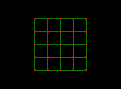
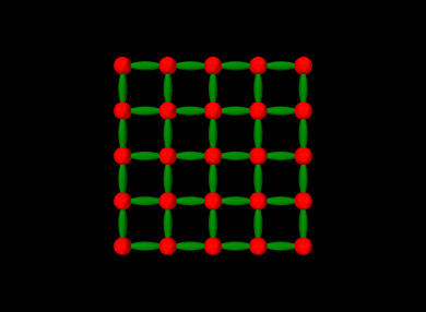
The Renderer methods drawPoints(RenderObject,PointStyle,double) and drawLines(RenderObject,LineStyle,double), described above, can be particularly useful for drawing the points or lines of a render object using different styles. For example, the following code fragment draws the grid of Listing 7 with points drawn as spheres with radius 0.1 and lines drawn as spindles with radius 0.05, with the results shown in Figure 2.23.
2.4.7 Multiple primitive groups
The RenderObject can have multiple groups of a particular primitive type. This is to allow for separate draw calls to render different parts of the object. For example, consider a triangular surface mesh consisting of a million faces that is to be drawn with the left half red, and the right half yellow. One way to accomplish this is to add a vertex color attribute to each vertex. This will end up being quite memory inefficient, since the renderer will need to duplicate the color for every vertex in the vertex buffer. The alternative is to create two distinct triangle groups and draw the mesh with two draw calls, changing the global color between them. New primitive groups can be created using the methods
Each of these creates a new group for the associated primitive type, sets it to be the current group, and returns an index to it.
A group for a particular primitive type is created automatically, if necessary, the first time an instance of that primitive is added to a render object.
Once created, the following methods can be used to set and query the different primitive groups:
Another set of methods can be used to query the primitives within a particular group:
Finally, the draw primitives described in Section 2.4.6 all have companion methods that allow the primitive group to be specified:
To illustrate group usage, we modify the grid example of Listing 7 so that the vertical and horizontal lines are each placed into different line groups:
Once this is done, the horizontal and vertical lines can be drawn with different colors by drawing the different groups separately:
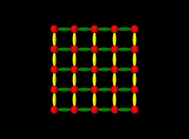
The results are show in Figure 2.24.
As noted in Section 2.4.5, it is possible to clear all primitives using clearPrimitives(). This will clear all primitives and their associated groups within the render object, while leaving vertices and attributes alone, allowing new primitives to then be constructed.
2.4.8 Drawing primitive subsets
In some circumstances, it may be useful to draw only a subset of the primitives in a render object, or to draw a subset of the vertices using a specified primitive type. There may be several reasons why this is necessary. The application may wish to draw different primitive subsets using different settings of the graphics context (such as different colors). Or, an application may use a single render object for drawing a collection of objects that are individually selectable. Then when rendering in selection mode (Section 2.7), it is it is necessary to render the objects separately so that the selection mechanism can distinquish them.
The two renderer methods for rendering primitive subsets are:
Each of these draws primitive subsets for the render object robj, using the vertices specified by idxs and the primitive type specified by mode. VertexIndexArray is a dynamically-sized integer array specialized for vertices. The second method allows a subset of idxs to be specified by an offset and count, so that the same index array can be used to draw different features.
The following example creates a render object containing three squares, and then uses drawVertices() to render each square individually using a different color:
Each square is added to the render object using the method addSquare(), which creates and adds the necessary vertices and line
segments, and also stores the line segment vertex indices in an index
array. The render() method then uses subsets of this index
array, specified by the offset/length pairs ![]() ,
, ![]() , and
, and
![]() , to render each square individually (using a different
color) via a call to drawVertices(). The result is shown in
Figure 2.25.
, to render each square individually (using a different
color) via a call to drawVertices(). The result is shown in
Figure 2.25.
In the above example, each square uses the same number of vertices (8) to draw its line segments, making it easy to determine the offset/length pairs required for each square. However, in more general cases a render object may contain features with variable numbers of vertices, and so determining the offset/length pairs may be more difficult. In such cases the application may find it useful to instead collect the vertex indices inside a FeatureIndexArray, which allows them to be grouped on a per-feature basis, with each feature identified by a number. The usage model looks like this:
After the feature index array has been built, the vertex index buffer can be obtained using fidxs.getVertices(), and the feature number and offset/length pair for each feature can be recovered using
where fidx is the index of the feature within the FeatureIndexArray. In some situations the feature number fnum and fidx may be the same, but in others they may be different. For example, each feature may be associated with an application component that has a unique number used for selection (Section 2.7), in which case the feature number can be set to the selection number.
The three squares example of Listing 8 can be reimplemented using FeatureIndexArray as follows:
2.5 Texture mapping
Some renderers provide support for texture mapping, including color, normal, and bump maps; whether or not they do can be queried via the methods hasColorMapping(), hasNormalMapping(), and hasBumpMapping(). If supported, such mappings may be set up and queried using the methods
The props argument to the set methods either contains the properties required to set up the mapping, or, if null, disables the mapping. When enabled, color, normal and bump maps will be applied to subsequent draw operations involving triangle primitives for which texture coordinates have been assigned to the vertices.
At present, texture coordinates can be defined for primitives using either draw mode (Section 2.3.4), or by creating a RenderObject (Sections 2.4 and 2.4.6). Texture coordinates are assigned using the OpenGL convention whereby
and
correspond to the lower left and upper right of the image, respectively.
Normal and bump mapping will not work if shading is set to Shading.NONE or Shading.FLAT. That’s because both of those shading modes restrict the use of normals when computing primitive lighting.
Renderers based on OpenGL 3 support color, normal and bump mapping. Those based on OpenGL 2 support only color mapping.
2.5.1 Texture mapping properties
The properties specified by ColorMapProps, NormalMapProps, or BumpMapProps contains the source data for the mapping along with information about how to map that data onto drawn primitives given their texture coordinates. These properties include:
- enabled
-
A boolean specifying whether or not the mapping is enabled;
- fileName
-
A string giving the name of the texture source file. This can be any image file in the format supported by the standrad package javax.imageio, which includes JPEG, PNG, BMP, and GIF;
- sWrapping
-
An instance of TextureMapProps.TextureWrapping specifying the wrapping of the s texture coordinate;
- tWrapping
-
An instance of TextureMapProps.TextureWrapping specifying the wrapping of the t texture coordinate;
- minFilter
-
An instance of TextureMapProps.TextureFilter specifing the minifying filter;
- magFilter
-
An instance of TextureMapProps.TextureFilter specifing the magnifying filter;
- borderColor
-
The color to be used when either sWrapping or tWrapping is set to TextureWrapping.CLAMP_TO_BORDER;
- colorMixing
-
For ColorMapProps only, an instance of Renderer.ColorMixing that specifies how the color map is combined with the nominal coloring of the underlying primitive, which is in turn determined by the current diffuse/ambient color and any vertex coloring that may be present (Section 2.3.7). The default value for this is MODULATE, implying that the color map is modulated by the nominal coloring. Not all renderers support all mixing modes; whether or not a particular color mixing is supported can be queried using
boolean hasColorMapMixing (ColorMixing cmix); - diffuseColoring
-
For ColorMapProps only, a boolean that specifies whether the color map should respond to diffuse/ambient lighting;
- specularColoring
-
For ColorMapProps only, a boolean that specifies whether the color map should respond to specular lighting;
- scaling
-
For NormalMapProps and BumpMapProps only, a float giving a scaling factor for either the x-y components of the normal map, or the depth of the bump map.
TextureMapProps.TextureWrapping is an enum that describes how texture coordinates outside the canonical
range of ![]() are handled. There are four available methods, which
correspond to those available in OpenGL:
are handled. There are four available methods, which
correspond to those available in OpenGL:
| Method | Description | OpenGL equivalent |
|---|---|---|
| REPEAT | pattern is repeated | GL_REPEAT |
| MIRRORED_REPEAT | pattern is repeated with mirroring | GL_MIRRORED_REPEAT |
| CLAMP_TO_EDGE | coordinates are clamped to |
GL_CLAMP_TO_EDGE |
| CLAMP_TO_BORDER | out of range coordinates are set to a border color | GL_CLAMP_TO_BORDER |
REPEAT is implemented by setting the integer part of the coordinate to 0. For MIRRORED_REPEAT, mirroring is applied when the integer part is odd. See Figure 2.26.

TextureMapProps.TextureFilter is an enum that describes the filtering that is applied when the source image needs to be either magnified or minified. Specifically, for a given pixel being textured, we use the filter to compute a texture value from the texels in the texture image. There are six filter types, corresponding to those available in OpenGL:
| Method | OpenGL equivalent |
|---|---|
| NEAREST | GL_NEAREST |
| LINEAR | GL_LINEAR |
| NEAREST_MIPMAP_NEAREST | GL_NEAREST_MIPMAP_NEAREST |
| LINEAR_MIPMAP_NEAREST | GL_LINEAR_MIPMAP_NEAREST |
| NEAREST_MIPMAP_LINEAR | GL_NEAREST_MIPMAP_LINEAR |
| LINEAR_MIPMAP_LINEAR | GL_LINEAR_MIPMAP_LINEAR |
NEAREST uses the texel nearest to the pixel center, while LINEAR uses a weighted average of the four texels nearest to the pixel center. The remaing four MIPMAP values perform the filtering with the aid of mipmaps, which are images of diminishing size used to accomodate lower resolution rendering of the primitive. The OpenGL documentation should be consulted for details. Mipmaps are generated automatically if one of the MIPMAP values is selected.
2.5.2 Texturing example using draw mode
 |
 |
 |
Color, normal, and bump maps can set up independently or combined with each other. Listing 10 gives a complete example, showing all three maps applied to a simple planar rectangle to make it look like a shiny brass plate embossed with an Egyptian friz pattern. A color map adds character to the brass appearance, a normal map adds a ”crinkled” effect, and a bump map adds the friz pattern.
Properties for the mappings are created by the method createMaps(), using the raw images shown in Figure 2.27, and stored in the member variables myColorMap, myNormalMap, and myBumpMap. It uses a method getDataFolder(), not shown, which returns the path to the folder containing the image files. Whether or not specific mappings are enabled is controlled by the member variables myColorMapEnabled, myNormalMapEnabled, and myBumpMapEnabled.
The render() method does the actual rendering. It begins by increasing the shininess (10 being shininer that the default of 32), and setting the base and specular colors. Setting a separate specular color is necessary for creating specular effects that stand out from the base color. Mappings are then set if enabled, and the renderer’s draw mode is then used to draw the plate using two triangles with texture coordinates assigned to the vertices. Figure 2.28 shows the rendered plate with different mapping combinations applied.
 |
 |
 |
 |
 |
 |
2.5.3 Texturing example using a render object
The example described in Section 2.5.2 can also be implemented using a render object. The modification involves adding code to create the render object, and then using it to perform the draw operation in the render() method:
The method createPlateRenderObject() creates a render object for the plate, using the same vertex and texture coordinate definitions found in Listing 10. prerender() then uses this method to creates the render object once, on demand. Because the render object in this example is fixed, it is not actually necessary to create it inside prerender(), but we do so because this is where it is recommended that render objects be maintained, particularly if they are being continuously updated with application data.
For an example of this mapping being implemented directly using a PolygonalMesh object and RenderProps, see Section 2.6.
2.6 Mesh Renderers
The package maspack.geometry defines utility classes for the rendering of its mesh objects PointMesh, PolylineMesh, and PolygonalMesh. These include PointMeshRenderer, PolylineMeshRenderer, and PolygonalMeshRenderer. Each of these provides the following methods:
where XXXMesh is PointMesh, PolylineMesh, or PolygonalMesh, as appropriate. The prerender() method creates (or updates) a RenderObject (Section 2.4) for the specified mesh, and the render() method then uses this to draw the mesh in accordance with the render properties props and rendering flags. If Renderer.HIGHLIGHT is set in flags, then the mesh is rendered using highlighting (Section 2.3.3.1), although exactly how this is done depends on the mesh type and the rendering properties specified. Because mesh renderers utilize render objects, for efficiency reasons they should be allowed to persist between rendering operations.
The basic pattern for using a mesh renderer within a renderable is to call its prerender and render methods within the corresponding methods for the renderable, as illustrated by the following example in which a renderable contains a PolygonalMesh that needs to be drawn:
In this example, the PolygonalMeshRenderer is created on demand inside prerender(), but it could be created elsewhere.
When drawing a mesh, a mesh renderer takes into account its mesh-to-world transform (as returned by getMeshToWorld()), and multiplies the current model matrix by this transform value. As indicated above, it also uses the render properties specified by the render() method’s props argument to control how the mesh is drawn. If meshes have vertex normals defined (as returned by getNormals()), then these will be used to support the shading style specified by the shading property. Mesh renderers will also render meshes with vertex-based coloring, for those that have colors defined (as returned by getColors()), with the color interpolation and mixing controlled by the mesh’s getColorInterpolation() and getVertexColorMixing() methods.
For polygonal meshes, PolygonalMeshRenderer will draw the edges separately if the render property drawEdges is true, using the color specified by edgeColor (or lineColor if the former is null). The face style is controlled by faceStyle. If shading is specified as FLAT, then PolygonalMeshRenderer will shaded the faces using the face normals instead of the vertex-based normals returned by getNormals().
PolygonalMeshRenderer will also apply any color, normal, or bump mappings that are specified in the render properties to meshes that have texture coordinates defined. For example, the following listing implements the mappings shown in Listing 10 and Figure 2.28 by creating a mesh to represent the plane and using a RenderProps object to store the required rendering properties:
In this example, the mesh is created using createRectangle(width,height,addTextureCoords) which generates a
rectangular triangular mesh with a specified size, and if addTextureCoords is true, assigns texture coordinates to the
vertices with ![]() and
and ![]() corresponding to the lower left and
upper right corners.
corresponding to the lower left and
upper right corners.
The mesh classes themselves, PointMesh, PolylineMesh, and PolygonalMesh, implement the Renderable interface, providing their own render properties and using mesh renderers to implement their prerender() and render() methods. They also provide versions of these methods in which the render properties are specified explicitly, bypassing the internal properties, as in
so that the mapping example above could also have been implemented as
2.7 Object Selection
Some viewer implementations provide support for the interactive selection of renderable components within the viewer via mouse-based selection. The results of such selection are then conveyed back to the application through a selection event mechanism, as discussed in Section 2.7.2.
In order to be selectable, a renderable should implement the interface IsSelectable, which extends IsRenderable with the following three additional methods:
The method isSelectable() should return true if the component is in fact selectable. Unless the component manages its own selection behavior (as described in Section 2.7.1), numSelectionQueriesNeeded() should return -1 and getSelection() should do nothing.
Whether or not a viewer supports selection can be queried by the method
which is also exposed in the Renderer interface. Selection is done using an internal selection repaint (whose results are not seen in the viewer display) for which the viewer creates a special selection frustum which is a sub-frustum of the current view. The selection process involves identifying the selectables that are completely or partially rendered within this selection frustum.
Left-clicking in the view window will create a selection frustum defined by a small (typically 5x5) sub-window centered on the current mouse position. This type of selection is usually handled to produce single selection of the most prominant selectable in the frustum.
Left-dragging in the view window will create a selection frustum defined by the drag box. This type of selection is usually handleed to produce multiple selection of all the selectables in the frustum.
Whether or not the current repaint step is a selection repaint can be determined within a render() method by calling the Renderer method isSelecting().
Within OpenGL-based viewers, selection is implemented in several different ways. If the selection mode requires all objects in the selection frustum, regardless of whether they are clipped by the depth buffer, then OpenGL occlusion queries are used. If only visible objects which have passed the depth test are desired, then a color-based selection scheme is used instead, where each object is rendered with a unique color to an off-screen buffer.
It is possible to restrict selection to specific types of renderables. This can be done by setting a selection filter in the viewer, using the methods
where ViewerSelectionFilter is an interface that implements a single method, isSelectable(selectable) that returns true if a particular selectable object should in fact be selected. Limiting rendering in this way allows components to be selected that might otherwise be hidden by non-selectable components in the foreground.
2.7.1 Implementing custom selection
By default, if the isSelectable() and numSelectionQueriesNeeded() methods of a selectable return true and -1, respectively, then selection will be possible for that object based on whether any portion of it is rendered in the selection frustum. No other programming work needs to be done.
However, in some cases it may be desirable for a selectable to mange it’s own selection. A common reason for doing this is that the selectable contains subcomponents which are themselves selectable. Another reason might be that only certain parts of what a component renders should be used to indicate selection.
A selectable manages its own selection by adding custom selection code within its render() method. This typically consists of surrounding the “selectable” parts of the rendering with a selection query block which is associated with an integer identifier. Selection query blocks can be invoked using the Renderer methods
For example, suppose we have a component which renders in three stages (A, B, and C), and we only want the component to be selected if the rendering for stage A or C appears in the selection frustum. Then we surround the rendering of stages A and C with selection queries:
It is not strictly necessary to conditionalize calls to beginSelectionQuery() and endSelectionQuery() (or beginSubSelection() and endSubSelection(), described below) on renderer.isSelecting(). That’s because if the renderer is not in selection mode, then these calls simply do nothing. However, conditionalizing the calls may be useful for code clarity or efficiency.
It is also necessary to indicate to the renderer how many selection queries we need, and what should be selected in response to a particular query. This is done by creating appropriate declarations for numSelectionQueriesNeeded() and getSelection() in the IsSelectable implementation. For the above example, those declarations would look like this:
The query index supplied to beginSelectionQuery() should be in the range 0 to numq-1, where numq is the value returned by numSelectionQueriesNeeded(). There is no need to use all requested selection queries, but a given query index should not be used more than once. When rendering associated with a particular query appears in the selection frustum, the system will (later) call getSelection() with qid set to the query index to determine what exactly has been selected. The selectable answers this by adding the selected component to the list argument. Typically only one item (the selected component) is added to the list, but other information can be placed there as well, if an application’s selection handler (Section 2.7.2) is prepared for it.
A component’s getSelection() method will be called for each selection query whose associated render fragment appears in the selection frustum. If a component is associated with multiple queries (as in the above example), then its getSelection() may be called multiple times.
Note that the use of beginSelectionQuery(qid) and endSelectionQuery() is conceptually similar to surrounding the render code with glLoadName(id) and glLoadName(-1), as is done when implementing selection in legacy OpenGL using the GL_SELECT rendering mode.
As another example, imagine that a selectable class Foo contains a list of selectable components, each of which may be selected individually. The “easy” way to handle this is for Foo to hand each component to the RenderList in it’s prerender() method (Section 2.2.2):
Rendering and selection of each component is then handled by the renderer.
However, if for some reason (efficiency, perhaps) it is necessary for Foo to render the components inside its own render() method, then it must also take care of their selection. This can be done by requesting and issuing selection queries for each one:
Note that a call to the Renderer method isSelectable(s) is used to determine which selectable components should actually be rendered when a selection render is being performed. This method returns true if s.isSelectable() returns true and if s is allowed by any selection filter that is currently active in the viewer.
In some cases, some of the selectable components within a class may normally be rendered at once using a single render object. However, when a selection render is performed, each such component must be rendered using a separate draw operation surrounded by the appropriate calls to begin/endSelectionQuery(). This can be done either by rendering each component using its own render method, or by rendering primitive subsets of the render object as described in Section 2.4.8. If the latter is done using a FeatureIndexArray, then the feature number can be used to store the selection query ID. For example, in the example of Listing 9, the render() method can be rewritten to normally draw all the squares at once (using the default color) with a single call to draw(RenderObject), or, when selecting, to render each square separately within a selection query block:
Finally, what if some of the components in the above example wish to manage their own selection? This can be detected if a component’s numSelectionQueriesNeeded() method return a non-negative value. In that case, Foo can let the component manage its selection by calling its render() method, surrounded with calls to beginSubSelection() and endSubSelection(), instead of beginSelectionQuery(int) and endSelectionQuery(), as in
The call to beginSubSelection() sets internal information in the renderer so that within the render() method for s, query indices in the range [0, numq-1] correspond to indices in the range [qid, qid+numq-1] as seen outside the render() method.
In addition, Foo must also add the number of selection queries required by its components to the value returned by its own numSelectionQueriesNeeded() method:
Finally, in its getSelection() method, Foo must delegate to components managing their own selection by calling their own getSelection() method. When doing this, it is necessary to offset the query index passed to the component’s getSelection() method by the base query index for that component, since as indicated above, query indices seen within a component are in the range [0, numq-1]:
2.7.2 Selection Events
Components selected by the viewer are indicated to the application via a selection listener mechanism, in which the application registers instances of ViewerSelectionListener with the viewer using the methods
The listener implements one method with the signature
from which information about the selection can be obtained via a ViewerSelectionEvent. This provides information about all the queries for which selection occured the methods
numSelectedQueries() returns the number of queries that resulted in a selection, getModifiersEx() returns the extended keyboard modifiers that were in play when the selection was requested, and getFlags() returns information flags about the selection (such as whether it was a DRAG selection or MULTIPLE selection is desired).
Information about the selected components is returned by getSelectedObjects(), which provides an array (of length numSelectedQueries()) of object lists for each selected query. Each object list is the result of the call to getSelection() for that selection query. As indicated in Section 2.7.1, each object list typically contains a single selected component, but may contain other information if the selection handler is prepared for it.
The array provided by getSelectedObjects() is ordered so that results for the most visible selectables appear first, so if the handler wishes to select only a single component, it should look at the beginning of the list. Also, if the rendering for a single component is associated with multiple selection queries, mutiple results may returned for that component.
![[LOGO]](data:image/png;base64,iVBORw0KGgoAAAANSUhEUgAAAAsAAAAOCAYAAAD5YeaVAAAAAXNSR0IArs4c6QAAAAZiS0dEAP8A/wD/oL2nkwAAAAlwSFlzAAALEwAACxMBAJqcGAAAAAd0SU1FB9wKExQZLWTEaOUAAAAddEVYdENvbW1lbnQAQ3JlYXRlZCB3aXRoIFRoZSBHSU1Q72QlbgAAAdpJREFUKM9tkL+L2nAARz9fPZNCKFapUn8kyI0e4iRHSR1Kb8ng0lJw6FYHFwv2LwhOpcWxTjeUunYqOmqd6hEoRDhtDWdA8ApRYsSUCDHNt5ul13vz4w0vWCgUnnEc975arX6ORqN3VqtVZbfbTQC4uEHANM3jSqXymFI6yWazP2KxWAXAL9zCUa1Wy2tXVxheKA9YNoR8Pt+aTqe4FVVVvz05O6MBhqUIBGk8Hn8HAOVy+T+XLJfLS4ZhTiRJgqIoVBRFIoric47jPnmeB1mW/9rr9ZpSSn3Lsmir1fJZlqWlUonKsvwWwD8ymc/nXwVBeLjf7xEKhdBut9Hr9WgmkyGEkJwsy5eHG5vN5g0AKIoCAEgkEkin0wQAfN9/cXPdheu6P33fBwB4ngcAcByHJpPJl+fn54mD3Gg0NrquXxeLRQAAwzAYj8cwTZPwPH9/sVg8PXweDAauqqr2cDjEer1GJBLBZDJBs9mE4zjwfZ85lAGg2+06hmGgXq+j3+/DsixYlgVN03a9Xu8jgCNCyIegIAgx13Vfd7vdu+FweG8YRkjXdWy329+dTgeSJD3ieZ7RNO0VAXAPwDEAO5VKndi2fWrb9jWl9Esul6PZbDY9Go1OZ7PZ9z/lyuD3OozU2wAAAABJRU5ErkJggg==)