2.5 Meshes
ArtiSynth makes extensive use of 3D meshes, which are defined in maspack.geometry. They are used for a variety of purposes, including visualization, collision detection, and computing physical properties (such as inertia or stiffness variation within a finite element model).
A mesh is essentially a collection of vertices (i.e., points) that are topologically connected in some way. All meshes extend the abstract base class MeshBase, which supports the vertex definitions, while subclasses provide the topology.
Through MeshBase, all meshes provide methods for adding and accessing vertices. Some of these include:
Vertices are implemented by Vertex3d, which defines the position of the vertex (returned by the method getPosition()), and also contains support for topological connections. In addition, each vertex maintains an index, obtainable via getIndex(), that equals the index of its location within the mesh’s vertex list. This makes it easy to set up parallel array structures for augmenting mesh vertex properties.
Mesh subclasses currently include:
- PolygonalMesh
-
Implements a 2D surface mesh containing faces implemented using half-edges.
- PolylineMesh
-
Implements a mesh consisting of connected line-segments (polylines).
- PointMesh
-
Implements a point cloud with no topological connectivity.
PolygonalMesh is used quite extensively and provides a number of methods for implementing faces, including:
The class Face implements a face as a counter-clockwise arrangement of vertices linked together by half-edges (class HalfEdge). Face also supplies a face’s (outward facing) normal via getNormal().
Some mesh uses within ArtiSynth, such as collision detection, require a triangular mesh; i.e., one where all faces have three vertices. The method isTriangular() can be used to check for this. Meshes that are not triangular can be made triangular using triangulate().
2.5.1 Mesh creation
Meshes are most commonly created using either one of the factory methods supplied by MeshFactory, or by reading a definition from a file (Section 2.5.5). However, it is possible to create a mesh by direct construction. For example, the following code fragment creates a simple closed tetrahedral surface:
Some of the more commonly used factory methods for creating polyhedral meshes include:
Each factory method creates a mesh in some standard coordinate
frame. After creation, the mesh can be transformed using the
transform(X) method, where X is either a rigid transform (
RigidTransform3d) or a more general affine
transform (AffineTransform3d).
For example, to create a rotated box centered on ![]() ,
one could do:
,
one could do:
One can also scale a mesh using scale(s), where s is a single scale factor, or scale(sx,sy,sz), where sx, sy, and sz are separate scale factors for the x, y and z axes. This provides a useful way to create an ellipsoid:
MeshFactory can also be used to create new meshes by performing Boolean operations on existing ones:
2.5.2 Setting normals, colors, and textures
Meshes provide support for adding normal, color, and texture information, with the exact interpretation of these quantities depending upon the particular mesh subclass. Most commonly this information is used simply for rendering, but in some cases normal information might also be used for physical simulation.
For polygonal meshes, the normal information described here is used only for smooth shading. When flat shading is requested, normals are determined directly from the faces themselves.
Normal information can be set and queried using the following methods:
The method setNormals() takes two arguments: a set of normal vectors (nrmls), along with a set of index values (indices) that map these normals onto the vertices of each of the mesh’s geometric features. Often, there will be one unique normal per vertex, in which case nrmls will have a size equal to the number of vertices, but this is not always the case, as described below. Features for the different mesh subclasses are: faces for PolygonalMesh, polylines for PolylineMesh, and vertices for PointMesh. If indices is specified as null, then normals is assumed to have a size equal to the number of vertices, and an appropriate index set is created automatically using createVertexIndices() (described below). Otherwise, indices should have a size of equal to the number of features times the number of vertices per feature. For example, consider a PolygonalMesh consisting of two triangles formed from vertex indices (0, 1, 2) and (2, 1, 3), respectively. If normals are specified and there is one unique normal per vertex, then the normal indices are likely to be
[ 0 1 2 2 1 3 ]
As mentioned above, sometimes there may be more than one normal per vertex. This happens in cases when the same vertex uses different normals for different faces. In such situations, the size of the nrmls argument will exceed the number of vertices.
The method setNormals() makes internal copies of the specified normal and index information, and this information can be later read back using getNormals() and getNormalIndices(). The number of normals can be queried using numNormals(), and individual normals can be queried or set using getNormal(idx) and setNormal(idx,nrml). All normals and indices can be explicitly cleared using clearNormals().
Color and texture information can be set using analogous methods. For colors, we have
When specified as float[], colors are given as RGB or
RGBA values, in the range ![]() , with array lengths of 3 and 4,
respectively. The colors returned by
getColors() are always RGBA
values.
, with array lengths of 3 and 4,
respectively. The colors returned by
getColors() are always RGBA
values.
With colors, there may often be fewer colors than the number of vertices. For instance, we may have only two colors, indexed by 0 and 1, and want to use these to alternately color the mesh faces. Using the two-triangle example above, the color indices might then look like this:
[ 0 0 0 1 1 1 ]
Finally, for texture coordinates, we have
When specifying indices using setNormals, setColors, or setTextureCoords, it is common to use the same index set as that which associates vertices with features. For convenience, this index set can be created automatically using
Alternatively, we may sometimes want to create a index set that assigns the same attribute to each feature vertex. If there is one attribute per feature, the resulting index set is called a feature index set, and can be created using
If we have a mesh with three triangles and one color per triangle, the resulting feature index set would be
[ 0 0 0 1 1 1 2 2 2 ]
Note: when a mesh is modified by the addition of new features (such as faces for PolygonalMesh), all normal, color and texture information is cleared by default (with normal information being automatically recomputed on demand if automatic normal creation is enabled; see Section 2.5.3). When a mesh is modified by the removal of features, the index sets for normals, colors and textures are adjusted to account for the removal.
For colors, it is possible to request that a mesh explicitly maintain colors for either its vertices or features (Section 2.5.4). When this is done, colors will persist when vertices or features are added or removed, with default colors being automatically created as necessary.
Once normals, colors, or textures have been set, one may want to know which of these attributes are associated with the vertices of a specific feature. To know this, it is necessary to find that feature’s offset into the attribute’s index set. This offset information can be found using the array returned by
For example, the three normals associated with a triangle at index ti can be obtained using
Alternatively, one may use the convenience methods
which return the attribute values for the ![]() -th vertex of
the feature indexed by fidx.
-th vertex of
the feature indexed by fidx.
In general, the various get methods return references to internal storage information and so should not be modified. However, specific values within the lists returned by getNormals(), getColors(), or getTextureCoords() may be modified by the application. This may be necessary when attribute information changes as the simulation proceeds. Alternatively, one may use methods such as setNormal(idx,nrml) setColor(idx,color), or setTextureCoords(idx,coords).
Also, in some situations, particularly with colors and textures, it may be desirable to not have color or texture information defined for certain features. In such cases, the corresponding index information can be specified as -1, and the getNormal(), getColor() and getTexture() methods will return null for the features in question.
2.5.3 Automatic creation of normals and hard edges
For some mesh subclasses, if normals are not explicitly set, they are computed automatically whenever getNormals() or getNormalIndices() is called. Whether or not this is true for a particular mesh can be queried by the method
Setting normals explicitly, using a call to setNormals(nrmls,indices), will overwrite any existing normal information, automatically computed or otherwise. The method
will return true if normals have been explicitly set, and false if they have been automatically computed or if there is currently no normal information. To explicitly remove normals from a mesh which has automatic normal generation, one may call setNormals() with the nrmls argument set to null.
More detailed control over how normals are automatically created may be available for specific mesh subclasses. For example, PolygonalMesh allows normals to be created with multiple normals per vertex, for vertices that are associated with either open or hard edges. This ability can be controlled using the methods
Having multiple normals means that even with smooth shading, open or hard edges will still appear sharp. To make an edge hard within a PolygonalMesh, one may use the methods
which control the hardness of edges between individual vertices, specified either directly or using their indices.
2.5.4 Vertex and feature coloring
The method setColors() makes it possible to assign any desired coloring scheme to a mesh. However, it does require that the user explicitly reset the color information whenever new features are added.
For convenience, an application can also request that a mesh explicitly maintain colors for either its vertices or features. These colors will then be maintained when vertices or features are added or removed, with default colors being automatically created as necessary.
Vertex-based coloring can be requested with the method
This will create a separate (default) color for each of the mesh’s vertices, and set the color indices to be equal to the vertex indices, which is equivalent to the call
where colors contains a default color for each vertex. However, once vertex coloring is enabled, the color and index sets will be updated whenever vertices or features are added or removed. Meanwhile, applications can query or set the colors for any vertex using getColor(idx), or any of the various setColor methods. Whether or not vertex coloring is enabled can be queried using
Once vertex coloring is established, the application will typically want to set the colors for all vertices, perhaps using a code fragment like this:
Similarly, feature-based coloring can be requested using the method
This will create a separate (default) color for each of the mesh’s features (faces for PolygonalMesh, polylines for PolylineMesh, etc.), and set the color indices to equal the feature index set, which is equivalent to the call
where colors contains a default color for each feature. Applications can query or set the colors for any vertex using getColor(idx), or any of the various setColor methods. Whether or not feature coloring is enabled can be queried using
2.5.5 Reading and writing mesh files
PolygonalMesh, PolylineMesh, and PointMesh all provide constructors that allow them to be created from a definition file, with the file format being inferred from the file name suffix:
| Suffix | Format | PolygonalMesh | PolylineMesh | PointMesh |
|---|---|---|---|---|
| .obj | Alias Wavefront | X | X | X |
| .ply | Polygon file format | X | X | |
| .stl | STereoLithography | X | ||
| .gts | GNU triangulated surface | X | ||
| .off | Object file format | X | ||
| .vtk | VTK ascii format | X | ||
| .vtp | VTK XML format | X | X |
The currently supported file formats, and their applicability to the different mesh types, are given in Table 2.1. For example, a PolygonalMesh can be read from either an Alias Wavefront .obj file or an .stl file, as show in the following example:
The file-based mesh constructors may throw an I/O exception if an I/O error occurs or if the indicated format does not support the mesh type. This exception must either be caught, as in the example above, or thrown out of the calling routine.
In addition to file-based constructors, all mesh types implement read and write methods that allow a mesh to be read from or written to a file, with the file format again inferred from the file name suffix:
For the latter methods, the argument zeroIndexed specifies zero-based vertex indexing in the case of Alias Wavefront .obj files, while fmtStr is a C-style format string specifying the precision and style with which the vertex coordinates should be written. (In the former methods, zero-based indexing is false and vertices are written using full precision.)
As an example, the following code fragment writes a mesh as an .stl file:
Sometimes, more explicit control is needed when reading or writing a mesh from/to a given file format. The constructors and read/write methods described above make use of a specific set of reader and writer classes located in the package maspack.geometry.io. These can be used directly to provide more explicit read/write control. The readers and writers (if implemented) associated with the different formats are given in Table 2.2.
| Suffix | Format | Reader class | Writer class |
|---|---|---|---|
| .obj | Alias Wavefront | WavefrontReader | WavefrontWriter |
| .ply | Polygon file format | PlyReader | PlyWriter |
| .stl | STereoLithography | StlReader | StlWriter |
| .gts | GNU triangulated surface | GtsReader | GtsWriter |
| .off | Object file format | OffReader | OffWriter |
| .vtk | VTK ascii format | VtkAsciiReader | |
| .vtp | VTK XML format | VtkXmlReader |
The general usage pattern for these classes is to construct the desired reader or writer with a path to the desired file, and then call readMesh() or writeMesh() as appropriate:
Both readMesh() and writeMesh() may throw I/O exceptions, which must be either caught, as in the example above, or thrown out of the calling routine.
For convenience, one can also use the classes GenericMeshReader or GenericMeshWriter, which internally create an appropriate reader or writer based on the file extension. This enables the writing of code that does not depend on the file format:
Here, fileName can refer to a mesh of any format supported by GenericMeshReader. Note that the mesh returned by readMesh() is explicitly cast to PolygonalMesh. This is because readMesh() returns the superclass MeshBase, since the default mesh created for some file formats may be different from PolygonalMesh.
2.5.6 Reading and writing normal and texture information
When writing a mesh out to a file, normal and texture information are also written if they have been explicitly set and the file format supports it. In addition, by default, automatically generated normal information will also be written if it relies on information (such as hard edges) that can’t be reconstructed from the stored file information.
Whether or not normal information will be written is returned by the method
This will always return true if any of the conditions described above have been met. So for example, if a PolygonalMesh contains hard edges, and multiple automatic normals are enabled (i.e., getMultipleAutoNormals() returns true), then getWriteNormals() will return true.
Default normal writing behavior can be overridden within the MeshWriter classes using the following methods:
where enable should be one of the following values:
- 0
-
normals will never be written;
- 1
-
normals will always be written;
- -1
-
normals will be written according to the default behavior described above.
When reading a PolygonalMesh from a file, if the file contains normal information with multiple normals per vertex that suggests the existence of hard edges, then the corresponding edges are set to be hard within the mesh.
2.5.7 Constructive solid geometry
ArtiSynth contains primitives for performing constructive solid geometry (CSG) operations on volumes bounded by triangular meshes. The class that performs these operations is maspack.collision.SurfaceMeshIntersector, and it works by robustly determining the intersection contour(s) between a pair of meshes, and then using these to compute the triangles that need to be added or removed to produce the necessary CSG surface.
The CSG operations include union, intersection, and difference, and are implemented by the following methods of SurfaceMeshIntersector:
Each takes two PolygonalMesh objects, mesh0 and mesh1, and creates and returns another PolygonalMesh which represents the boundary surface of the requested operation. If the result of the operation is null, the returned mesh will be empty.
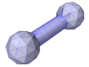
The example below uses findUnion to create a dumbbell shaped mesh from two balls and a cylinder:
The balls and cylinder are created using the MeshFactory methods createIcosahedralSphere() and createCylinder(), where the latter takes arguments ns, nr, and nh giving the number of slices along the circumference, the number of radial segments on each end cap, and the number of height segments along the length. The final resulting mesh is shown in Figure 2.1.
![[LOGO]](data:image/png;base64,iVBORw0KGgoAAAANSUhEUgAAAAsAAAAOCAYAAAD5YeaVAAAAAXNSR0IArs4c6QAAAAZiS0dEAP8A/wD/oL2nkwAAAAlwSFlzAAALEwAACxMBAJqcGAAAAAd0SU1FB9wKExQZLWTEaOUAAAAddEVYdENvbW1lbnQAQ3JlYXRlZCB3aXRoIFRoZSBHSU1Q72QlbgAAAdpJREFUKM9tkL+L2nAARz9fPZNCKFapUn8kyI0e4iRHSR1Kb8ng0lJw6FYHFwv2LwhOpcWxTjeUunYqOmqd6hEoRDhtDWdA8ApRYsSUCDHNt5ul13vz4w0vWCgUnnEc975arX6ORqN3VqtVZbfbTQC4uEHANM3jSqXymFI6yWazP2KxWAXAL9zCUa1Wy2tXVxheKA9YNoR8Pt+aTqe4FVVVvz05O6MBhqUIBGk8Hn8HAOVy+T+XLJfLS4ZhTiRJgqIoVBRFIoric47jPnmeB1mW/9rr9ZpSSn3Lsmir1fJZlqWlUonKsvwWwD8ymc/nXwVBeLjf7xEKhdBut9Hr9WgmkyGEkJwsy5eHG5vN5g0AKIoCAEgkEkin0wQAfN9/cXPdheu6P33fBwB4ngcAcByHJpPJl+fn54mD3Gg0NrquXxeLRQAAwzAYj8cwTZPwPH9/sVg8PXweDAauqqr2cDjEer1GJBLBZDJBs9mE4zjwfZ85lAGg2+06hmGgXq+j3+/DsixYlgVN03a9Xu8jgCNCyIegIAgx13Vfd7vdu+FweG8YRkjXdWy329+dTgeSJD3ieZ7RNO0VAXAPwDEAO5VKndi2fWrb9jWl9Esul6PZbDY9Go1OZ7PZ9z/lyuD3OozU2wAAAABJRU5ErkJggg==)