9.7 Application to muscle wrapping
It is sometimes possible to use skinning as a computationally cheaper way to implement muscle wrapping (Chapter 8).
Typically, the end points (i.e., origin and insertion points) of a point-to-point muscle are attached to different bodies. As these bodies move with respect to each other, the path of the muscle may wrap around portions of these bodies and perhaps other intermediate bodies as well. The wrapping mechanism of Chapter 8 manages this by performing the computations necessary to allow one or more wrappable segments of a MultiPointSpring to wrap around a prescribed set of rigid bodies. However, if the induced path deformation is not too great, it may be possible to achieve a similar effect at much lower computational cost by simply “skinning” the via points of the multipoint spring to the underlying rigid bodies.
The general approach involves:
-
1.
Creating a SkinMeshBody which references as master bodies the bodies containing the origin and insertion points, and possibly other bodies as well;
-
2.
Creating the wrapped muscle using a MultiPointSpring with via points that are attached to the skin body.
It should be noted that for this application, the skin body does not need to contain a mesh. Instead, “skinning” connections can be made solely between the master bodies and the via points. An easy way to do this is to simply use skin body markers as via points. Another way is to create the via points as separate particles, and then attach them to the skin body using one of its createPointAttachment methods.
It should also be noted that unlike with the wrapping methods of Chapter 8, skin-based wrapping can be applied around FEM models as well as rigid bodies.
Generally, we observe better wrapping behavior if the frameBlending property of the SkinMeshBody is set to DUAL_QUATERNION_LINEAR instead of the default value of LINEAR.
9.7.1 Example: wrapping for a finger joint
An example of skinning-based muscle wrapping is given by artisynth.demos.tutorial.PhalanxSkinWrapping, which is identical to the demo artisynth.demos.tutorial.PhalanxWrapping except for using skinning to achieve the wrapping effect. The portion of the code which differs is shown below:
First, a SkinMeshBody is created referencing the proximal and distal bones as master bodies, with the frameBlending property set to DUAL_QUATERNION_LINEAR (lines 1-6). Next, we create a set of three via points that will be attached to the skin body to guide the muscle around the joint in lieu of making it actually wrap around a cylinder (lines 7-9).
In the original PhalanxWrapping demo, a RigidCylinder was used as a muscle wrap surface. In this demo, we replace this with a simple cylindrical mesh which has no dynamic function but allows us to visualize the wrapping behavior of the via points (lines 11-18). The muscle itself is created using the three via points but with no wrappable segments or bodies (lines 20-30).
A control panel is added to allow for the adjustment of the skin body’s frameBlending property (lines 32-35). Finally, render properties are set as for the original demo, only with the skin body markers rendered as white spheres to make them more visible (lines 37-41).
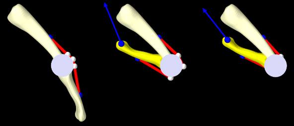
To run this example in ArtiSynth, select All demos > tutorial > PhalanxSkinWrapping from the Models menu. The model should load and initially appear as in Figure 9.7 (left). The pull tool can then be used to move the distal joint while simulating, to illustrate how well the via points “wrap” around the joint, using the cylindrical mesh as a visual reference (Figure 9.7, middle). Changing the frameBlending property to LINEAR results in a less satisfactory behavior (Figure 9.7, right).
![[LOGO]](data:image/png;base64,iVBORw0KGgoAAAANSUhEUgAAAAsAAAAOCAYAAAD5YeaVAAAAAXNSR0IArs4c6QAAAAZiS0dEAP8A/wD/oL2nkwAAAAlwSFlzAAALEwAACxMBAJqcGAAAAAd0SU1FB9wKExQZLWTEaOUAAAAddEVYdENvbW1lbnQAQ3JlYXRlZCB3aXRoIFRoZSBHSU1Q72QlbgAAAdpJREFUKM9tkL+L2nAARz9fPZNCKFapUn8kyI0e4iRHSR1Kb8ng0lJw6FYHFwv2LwhOpcWxTjeUunYqOmqd6hEoRDhtDWdA8ApRYsSUCDHNt5ul13vz4w0vWCgUnnEc975arX6ORqN3VqtVZbfbTQC4uEHANM3jSqXymFI6yWazP2KxWAXAL9zCUa1Wy2tXVxheKA9YNoR8Pt+aTqe4FVVVvz05O6MBhqUIBGk8Hn8HAOVy+T+XLJfLS4ZhTiRJgqIoVBRFIoric47jPnmeB1mW/9rr9ZpSSn3Lsmir1fJZlqWlUonKsvwWwD8ymc/nXwVBeLjf7xEKhdBut9Hr9WgmkyGEkJwsy5eHG5vN5g0AKIoCAEgkEkin0wQAfN9/cXPdheu6P33fBwB4ngcAcByHJpPJl+fn54mD3Gg0NrquXxeLRQAAwzAYj8cwTZPwPH9/sVg8PXweDAauqqr2cDjEer1GJBLBZDJBs9mE4zjwfZ85lAGg2+06hmGgXq+j3+/DsixYlgVN03a9Xu8jgCNCyIegIAgx13Vfd7vdu+FweG8YRkjXdWy329+dTgeSJD3ieZ7RNO0VAXAPwDEAO5VKndi2fWrb9jWl9Esul6PZbDY9Go1OZ7PZ9z/lyuD3OozU2wAAAABJRU5ErkJggg==)