5 Model Manipulation
Various tools located within the selection toolbar at the left of the main ArtiSynth frame allow models to be manipulated in various ways. These include modifying component locations, orientations, and geometry using the transformer tools (Section 5.2), exerting point forces on selected components using the pull controller (Section 5.3), and adding marker points to certain components types (Section 5.4).
The behavior of these tools is somewhat context dependent. For example, the transformer tools will only transform those transformable components which implement the TransformableGeometry interface. The behavior may also vary depending on whether or not simulation is in progress.
5.1 Dragger fixtures
The transformation tools employ the dragger fixtures shown in Figure 24, which allow 3D geometrical transformations to be performed within the viewer.
- Translator
-
Effects a translation. The x, y, and z axes are indicated by red, green, and blue lines. Dragging any line causes a one-dimensional motion along the associated axis. Dragging one of the boxes causes a two-dimensional motion in the associated plane.
- Rotator
-
Effects a rotation. Rotation about the x, y, and z axes is indicated by red, green, and blue circles. Selecting and dragging along one of these circles produces a rotation about the corresponding axis.
- TransRotator
-
Combines the translator and rotator into a single tool. One difference is that the axes of the transRotator move with any rotation, and so operations are done with respect to the transRotator coordinate frame at the beginning of the drag.
Under the default mouse bindings, the basic drag operations involving these fixtures are invoked using the left mouse button with no modifier keys. Additional modifier keys allow constrained transformation or repositioning of the fixture, as described below.
5.2 Transformer tools
A number of transformer tools use the dragger fixtures described above to translate, rotate, and scale components. Once a tool is activated, then selecting one or more transformable components will cause the corresponding dragger fixture to appear in the viewer at the components’ location. If a single component is selected and that component is associated with a coordinate frame (by implementing the HasCoordinateFrame interface), then the dragger’s initial position and orientation are aligned with this coordinate frame. Otherwise, the dragger is initially placed at the center of the selected components with an orientation aligned to world coordinates.
The initial dragger orientation can be adjusted in the following ways:
-
1.
To request that a dragger’s initial orientation is always aligned with world coordinates, choose “Interaction ...” from the Settings menu and set initDraggersInWorld to true.
-
2.
Conversely, when transforming a set of point-like objects which lie either within a plane or along a straight line, it can be useful to align the dragger’s orientation to the points. To request this behavior, choose “Interaction ...” from the Settings menu and set alignDraggersToPoints to true.
The transformer tools include:
![]() Translation:
Translation:
Translates selected components using the translator dragger.
![]() Rotation:
Rotation:
Rotates selected components using the rotator dragger.
![]() TransRotation:
TransRotation:
Translates and rotates selected components
using the transRotate dragger. The transformation reference frame
moves with the tool.
![]() Constrained translation:
Constrained translation:
Translates selected components using the translate dragger while ensuring that
they are constrained to remain on a surface mesh. Only components with
an associated surface mesh (such as FrameMarkers attached to a
RigidBody) can be transformed this way.
![]() Scaling:
Scaling:
Scales selected components using the transrotator
fixture. Instead of translating, translational drag operations
scale the component along the x, y, or z axes, or in the
x-y, y-z, or z-x planes. Rotational operations, if
used in conjunction with an appropriate modifier key,
can be used to change the orientation of the scaling axes,
as described in 5.2.2.
5.2.1 Constrained transformation
Under the default mouse bindings, pressing the SHIFT modifier key causes drag operations to be constrained to discrete step sizes. Rotation operations are constrained to intervals of five degrees, while translation operations are constrained to either the grid spacing (if a grid is selected, see 3.7), or to a suitable well-rounded number depending on the viewer’s zoom level.
5.2.2 Transformer repositioning
Under the default mouse bindings, pressing the CTRL modifier key causes the dragger fixture to move independently of the selected objects. This allows the transformer frame to be changed relative to the selected objects being manipulated; this is particularly useful for changing the orientation of the scaling directions in the scaling tool.
If a single objects is being transformed (as opposed to a group of selected objects), the application will remember the modified transformer frame if the object is deselected and then reselected. The default frame can be restored by hitting the ’u’ key (Section 5.2.3).
5.2.3 Changing the transformer base frame
By default, a transformer is assigned a local coordinate frame for the object(s) that it is positioning, based on either the object’s own body frame (if it has one), or the objects’ bounding box. This frame will then move with the transformer, and may also move relative to the object(s) if the transformer is repositioned (Section 5.2.2).
Sometimes, it may be desirable to explicitly reset the transformer’s frame. This may be done using the following shortcut keys in the viewer (while a transformer tool is being used and objects are selected):
- w
-
Set the transformer frame to the world coordinate system, allowing subsequent transformations to be performed in world coordinates;
- b
-
Reset the transformer frame to the local frame for the object(s), based on either the object’s body frame or the objects’ bounding box. For single a object, any changes to the transformer frame that were made using the CTRL modifier (Section 5.2.2) will be restored.
- u
-
Reset the transformer frame to the default local frame for the object(s), based on either the object’s body frame or the objects’ bounding box. For single a object, any changes to the transformer frame that were made using the CTRL modifier (Section 5.2.2) will be removed.
5.2.4 Flipping transformer axes forward
Sometimes, a user may discover that a transformer’s frame is inconveniently oriented, with one or more axes directed away from the viewer window, obscuring them and making the transformer difficult to use. This can be mitigated by hitting the ’f’ key in the viewer, which will cause the axes of any active transformer to be flipped so that they are directed toward the viewer window (Figure 25).
5.2.5 Resizing transformers
ArtiSynth will try to automatically set a transformer’s dragger fixture to an appropriate size. In some cases, the user may wish to change this size, which may be done using the following shortcut keys in the viewer (while a transformer tool is being used and objects are selected):
- CTRL u or UP_ARROW
-
Increases the transformer size.
- CTRL d or DOWN_ARROW
-
Decreases the transformer size.
The default size can be restored by hitting the ’u’ key (Section 5.2.3).
5.3 Pull manipulation
![]() Pull tool:
Pull tool:
Pulls on certain components using a spring-like force
when simulation is running.
Selecting the pull tool allows a user to interactively apply a spring-like force to certain component types by clicking on it and then dragging (Figure 26). Double clicking on the component adds a pull point that persists between mouse clicks; to remove the pull point, double click on the viewer background.
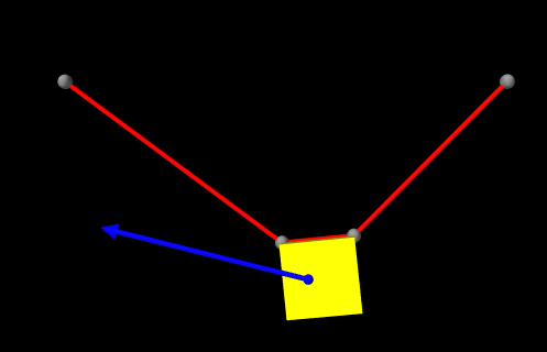
The pull tool works on points, rigid bodies, FEM models, or any other component that implements the PointAttachable interface and has a surface mesh. Pull manipulation is only effective when simulation is running. It works by adding a special PullController to the current root model’s set of controllers. When attached to the root model, the controller attempts to estimate an appropriate spring stiffness based on the overall mass and dimensions of the first underlying MechModel.
If necessary, the pull tool’s stiffness and rendering properties can be adjusted. To do this, right click on tool’s button and choose “Edit properties ...”. Properties include:
- renderColor
-
Color of the point and arrow rendered by the tool.
- radiusRatio
-
Radius of the point, as a fraction of the screen width.
- stiffness
-
Stiffness of the spring.
5.4 Marker tool
![]() Marker tool:
Marker tool:
Adds point markers to certain components.
Selecting the marker tool allows a user to interactively add point markers to various components in the model.
Markers can be added by double-clicking on rigid bodies, FEM models, and other components that implement the IsMarkable interface.
Markers are typically added to a component’s surface mesh, and in such cases it is necessary that this surface mesh be visible. For FEM models in particular, the surfaceRendering property should be set to something other than None. To ensure this is the case, select the FEM model, right-click and choose “Edit properties ...”, and examine the setting for surfaceRendering. An FEM model can sometimes appear to have a visible surface mesh, even if it doesn’t, if its elementWidgetSize property is close to 1.
The markers themselves are added to the current root model at a location that depends on the component being marked:
-
•
Rigid bodies: marker is added to the frameMarker list for the body’s parent MechModel;
-
•
FEM models: marker is added to the FEM model’s marker list;
-
•
IsMarkable components: marker is added to the root model’s marker list (which is created on demand if needed).
In order for added markers to be visible, the component list into which they are placed needs to be visible, with its point rendering properties set to appropriate values. That usually means that pointStyle is set to SPHERE or CUBE, with pointRadius set to a value commensurate with the model’s dimensions, or pointStyle is set to POINT, with pointSize set to a sufficiently large value in pixels. If not set within the list itself, the point rendering properties will be inherited from ancestor components. For example, if a MechModel’s point render properties are set for good visibility, then all points within subcomponents will be visible unless these setting have been overridden at a lower point in the hierarchy.
If markers are not appearing when using the marker tool, use the navigation panel to open the component list to which the markers are added (as described above). Verify that markers are actually being appended to the end of the list. If they are not, ensure that the component’s surface mesh is visible. If they are, select the list itself, right-click, and choose “Edit render props ...”. Check that visible is true, and that pointStyle and pointRadius (or pointSize) are set appropriately.
Once created, markers can be removed by selecting them and choosing Delete from the context menu.
5.5 Measurement tool
![]() Measurement tool:
Measurement tool:
Measures distance between two points selected in the viewer.
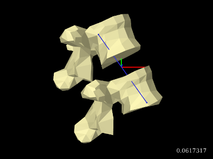
Selecting the measurement tool allows a user to measure distances between model features. A cross-hair cursor is enabled, with which the user selects two point locations in the viewer. When the second location is selected, the distance is displayed in the lower right corner of the viewer (Figure 27).
Once two locations are selected, subsequent selection moves the second location, making it easy to find distances between the first location and different second locations. Double clicking will clear all locations and allow the first location to be reselected.
Locations that can currently be selected by the measurement tool include points, frames, and any point on a surface mesh. Locations on point-to-point springs cannot currently be selected but we expect this to implemented soon.
The measurement tool’s rendering properties can be adjusted. To do this, right click on the tool’s button and choose “Edit properties ...”. Properties include:
- renderColor
-
Color of the points and line between them.
- radiusRatio
-
Radius of the points, as a fraction of the screen width.
![[LOGO]](data:image/png;base64,iVBORw0KGgoAAAANSUhEUgAAAAsAAAAOCAYAAAD5YeaVAAAAAXNSR0IArs4c6QAAAAZiS0dEAP8A/wD/oL2nkwAAAAlwSFlzAAALEwAACxMBAJqcGAAAAAd0SU1FB9wKExQZLWTEaOUAAAAddEVYdENvbW1lbnQAQ3JlYXRlZCB3aXRoIFRoZSBHSU1Q72QlbgAAAdpJREFUKM9tkL+L2nAARz9fPZNCKFapUn8kyI0e4iRHSR1Kb8ng0lJw6FYHFwv2LwhOpcWxTjeUunYqOmqd6hEoRDhtDWdA8ApRYsSUCDHNt5ul13vz4w0vWCgUnnEc975arX6ORqN3VqtVZbfbTQC4uEHANM3jSqXymFI6yWazP2KxWAXAL9zCUa1Wy2tXVxheKA9YNoR8Pt+aTqe4FVVVvz05O6MBhqUIBGk8Hn8HAOVy+T+XLJfLS4ZhTiRJgqIoVBRFIoric47jPnmeB1mW/9rr9ZpSSn3Lsmir1fJZlqWlUonKsvwWwD8ymc/nXwVBeLjf7xEKhdBut9Hr9WgmkyGEkJwsy5eHG5vN5g0AKIoCAEgkEkin0wQAfN9/cXPdheu6P33fBwB4ngcAcByHJpPJl+fn54mD3Gg0NrquXxeLRQAAwzAYj8cwTZPwPH9/sVg8PXweDAauqqr2cDjEer1GJBLBZDJBs9mE4zjwfZ85lAGg2+06hmGgXq+j3+/DsixYlgVN03a9Xu8jgCNCyIegIAgx13Vfd7vdu+FweG8YRkjXdWy329+dTgeSJD3ieZ7RNO0VAXAPwDEAO5VKndi2fWrb9jWl9Esul6PZbDY9Go1OZ7PZ9z/lyuD3OozU2wAAAABJRU5ErkJggg==)