10.1 Overview
ArtiSynth supports an inverse simulation capability that allows the computation of the excitation signals (for muscles and other actuators) needed to track target trajectories for a set of source components within the model (typically points or frames). This is achieved using a specialized controller component known as a TrackingController, defined in the package
artisynth.core.inverse
An application model creates the tracking controller and configures it with the source components, the exciter components needed to effect the tracking, and probes or controllers to specify the target trajectories. Then at each simulation time step the controller computes the excitations (i.e., signals to the exciter components) that allow the trajectories to be followed as closely as possible, in a manner conceptually similar to computed muscle control in OpenSim [7].
In earlier versions of ArtiSynth it was necessary to run inverse simulation with hybrid solving disabled. That limitation has been removed.
10.1.1 Tracking controller operation
Let  ,
 and
 be composite vectors describing the positions,
velocities and forces of all the components in the application model, and let
 be a vector of excitation signals for all the excitation components
available to the controller. can be decomposed into
 |
(10.1) |
where  are the passive forces corresponding to zero excitation, and
 are the active forces. During simulation, the controller computes
values for to best track the target trajectories.
In the case of motion tracking, let  and
 be the subvectors of and
containing the positions and velocities of the source components, and let
 and
 be the corresponding target trajectories. At the beginning of
each time step, the controller compares the current source velocity state
 with the desired target state
 and uses this to
determine a desired source velocity
 for the next time step;
this computation is done by the motion tracker (Figure
10.1, Section 10.1.2).
An excitation generator then computes in order to try and make
match (Section 10.1.3).
The target state is maintained within a set of target objects that the controller creates to mirror each source
component (Section 10.2.2), and the target positions
and velocities of these objects are typically specified using probes
or controllers. Target velocities do not have to be explicitly set; if
they are not, then they are either estimated from the position targets
(see the property estimateTargetVelocity in
Section 10.2.2), or assumed to be 0.
The excitation generator accepts a desired velocity
10.1.2 Motion tracking
As mentioned above, the motion tracker computes a desired source velocity
for the next time step based on the current source state and
desired target state . This can be done in two ways: chase control (the default), and PD control.
Both methods take account of the fact that the target and source states are
known at different times. Let  be the step size, and let
 and
 denote the source position and velocity at the start of the step. Since input
probes and other controllers are applied before the tracking controller, the
target state has already been advanced to the end of the step when the
tracking controller is called, and so is given by
 and
 . The position error at the start of the step is then estimated as
 |
(10.2) |
If is consistent with the motion of , then  approximates
 . If it is not (for instance, if is assumed to be 0
because it is neither specified nor estimated), then also contains a
velocity correction that helps compensate for this.
10.1.2.1 Chase control
Chase control sets to , plus an additional velocity that tries to
reduce the position error over a specified time interval  , called the chase time:
 |
(10.3) |
If the source attains , the position error decays as  .
When
 , (10.3) reduces to
 |
which places the source on the target at the end of each step, regardless of
. This most closely reproduces the target trajectory, and is often
the appropriate choice for inverse simulation.
should not be less than , since the source would then overshoot the
target. Larger values of produce smoother excitations and reduce
sensitivity to roughness in the target trajectory and to system nonlinearities,
but introduce a tracking lag of about  if is neither
specified nor estimated (Section 10.2.2). With
specified or estimated, a chase time of a few steps can give smoother
excitations with little or no loss of accuracy.
is controlled by the chaseTime property of the motion target term
(Section 10.3.3). In accordance with the need
to keep  , is determined from
 |
Setting chaseTime to 0 (the default) then ensures that .
10.1.2.2 PD control
PD control computes a desired source acceleration according to
 |
(10.4) |
which, if attained, causes the position error  to obey
 |
(10.5) |
This is then integrated over the step to determine :
 |
(10.6) |
where is given by (10.2) and  is the target
velocity from the previous step. (If this is unavailable, as on the first
step or after a reset, is used instead.) Equation
(10.6) is equivalent to
 , with
the target acceleration
 approximated by
 .
From (10.5), the gains determine a natural frequency
 and a damping ratio
 . It is often
easier to specify the gains in terms of
 and a time constant
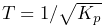 , using
 |
For critical damping ( ), the position error following a step
change decays as
 , falling to 10% of its initial value
after about
 . Values of less than 1 lead to overshoot, while
values greater than 1 lead to a slower response. Unlike chase control, the
resulting behavior does not depend on the step size , provided that
 and
 are both less than about 1; otherwise, the discrete
control law no longer approximates (10.5) and a warning
is printed. The default values for
 and
 are
 and
 ,
corresponding to
 and .
PD control is enabled by setting the usePDControl property of the
motion target term to true, and adjusted by setting its Kp and
Kd properties. The gains can also be set using the pdTimeConstant and pdDampingRatio
properties, which set Kp and Kd according to and
(Section 10.3.3).
Chase control is a special case of PD control: setting 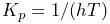 and
 in (10.6) yields (10.3). That is,
chase control eliminates any velocity error within a single step, so that its
derivative gain depends on . PD control offers a greater ability to adjust
the tracking behavior, but works best when is specified or estimated
(Section 10.2.2). Otherwise, the derivative term will damp the
source velocity toward 0, producing a tracking lag of about
 .
With either method, target trajectories should be smooth. For example, marker data sampled at a fixed rate and interpolated linearly has velocity discontinuities at each sample. If the step size is smaller than the sample interval, these can cause the computed excitations to oscillate at the sample rate. Using cubic interpolation for the target probe avoids this.
10.1.3 Generating excitations using a quadratic program
Given , the excitation generator computes to try and ensure that the
velocity at the end of the subsequent time step,  , satisfies
 |
(10.7) |
This is accomplished using a quadratic program.
First, we linearize (10.1) with respect to changes
in given by  ,
where
 is the current set of excitation values and
 is evaluated at :
 |
(10.8) |
Given this, it is possible to show that
 |
where  is the velocity that will result if is unchanged and
 is a
motion excitation response matrix. To best follow the trajectory, we
can compute
 to minimize the quadratic cost function
 |
(10.9) |
If we add in the constraint that excitations lie in the range  , the problem takes the form of a quadratic program (QP)
 |
|||
 |
(10.10) |
In order to prioritize some target terms over others,
 can be modified to include weights, according to
 |
(10.11) |
where  is a diagonal weighting matrix.
To handle excitation redundancy, where the size of exceeds the
size of , we can add a regularization term
 |
(10.12) |
that resolves redundancy in favour of lowering a weighted norm of
.  is a diagonal weight matrix that can be used to adjust
the relative importance of specific excitations.
The matrix
presented in [11]. In particular, increasing an element of
, whereas
The motion and regularization terms are combined to form an overall cost function
 |
|||
 |
(10.13) |
where  and
 are additional scalar weights that balance the
different cost terms.
10.1.4 Force tracking
Other cost terms can be added to the tracking controller. For
instance, we can request a force trajectory  for a selected set
of force effectors. As with motions, the forces of these effectors
 at the end of step
 are linearly related to via
 |
where  is the force if is unchanged and
 is
the force excitation response matrix. The force trajectory can
then be tracked by minimizing
 |
(10.14) |
where  is a diagonal weighting matrix.
When tracking force targets, the target force trajectory is fed
directly into the excitation generator (Figure 10.2); there
is no equivalent of the motion tracker.
With force tracking included, the full QP takes the form
 |
|||
|
(10.15) |
10.1.5 Non-incremental computation
In many cases, the system forces are actually linear with respect to
, such that in (10.1) takes the form
 |
(10.16) |
When that is true,
 |
and the cost terms and QP can be defined with respect to the
full excitation values instead of . The motion term,
for example, becomes
 |
where is now the velocity that results when  (and similarly for the force term, with the force when ), while the regularization term becomes simply
 . The QP then takes the form
 |
|||
 |
(10.17) |
The original tracking controller assumed that forces are linear in and
used (10.17) in place of (10.15).
Non-incremental computation can still be enabled by setting the tracking
controller property computeIncrementally to false (Section
10.3.2), but it should only be used when the forces
are (approximately) linear in . Even then, incremental computation
usually gives equal or better tracking at the same computational cost.
The main reasons to enable non-incremental computation are:
-
•
To reproduce the results of models that were developed using non-incremental computation, which was the default in earlier versions of ArtiSynth.
-
•
Non-incremental computation can sometimes give slightly smoother excitations, at the expense of tracking accuracy. For example, in an arm model with a soft FEM bone, mean excitation changes per step were about 45% lower with non-incremental computation, while the tracking error was about 12% higher.
10.1.6 Setting up the tracking controller
Applications will generally set up a tracking controller using the following steps inside the application’s build() method:
-
1.
Create an instance of TrackingController and add it to the application using the root model’s addController() method.
-
2.
Configure the controller with the available excitation components using its addExciter(ex) and addExciter(weight,ex) methods.
-
3.
Configure the controller to track position or force trajectories for selected source components, which may include Point, Frame, or ForceEffector components. These are specified to the controller using methods such as addPointTarget(point), addFrameTarget(frame), and addForceEffectorTarget(forceEffector). These methods return a target object, which is allocated and maintained by the controller, and which is used for specifying the target positions or forces.
-
4.
Create input probes or controllers to specify the desired trajectories for the sources added in Step 3. Trajectories are specified by using probes or controllers to set the appropriate properties of the target objects returned by the addXXXTarget() methods. Likewise, output probes or monitors can be created to record the excitations and the tracked positions or forces of the sources.
-
5.
Add other cost terms as needed. These may include an L2 regularization term, added using the controller’s addL2RegularizationTerm() method. Regularization attempts to minimize the norm of the excitation values and is needed to resolve redundancy if the excitation set has more degrees of freedom than the target space.
For historical reasons, the target position and target velocity properties described in Section 5.3.1.1 are not used by the tracking controller for target components; therefore, probes controlling target positions and velocities should be bound to the position and velocity properties.
-
6.
Set controller configuration parameters.
10.1.7 Example: moving a point with multiple Muscles
 |
 |
A simple example illustrating the steps of Section 10.1.6 is given by
artisynth.demos.tutorial.InverseParticle
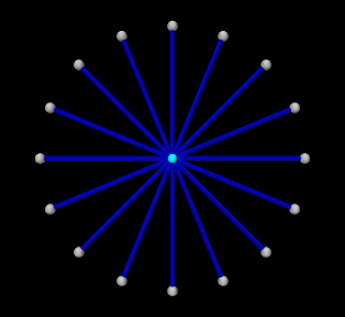
which uses a set of point-to-point muscles to drive the position of a single particle. The model consists of a single dynamic particle, initially located at the origin, attached to a set of 16 point-to-point muscles arranged radially around it. A tracking controller is created to control the excitations of these muscles so as to enable the particle to follow a trajectory specified by a probe. The code for the model, without the package and import directives, is listed below:
The build() method begins by creating a MechModel in the usual way
and disabling gravity (lines 35-37). The particle to be controlled is then
created and placed at the origin and with a damping factor of 0.1 (lines
40-42). Next, the particle is attached to a set of point-to-point muscles that
are arranged radially around it (lines 45-48). These are created using the
method createMuscle() (lines 13-31), which attaches each to a fixed
non-dynamic particle located a distance of dist from the origin, and sets
its material to a SimpleAxialMuscle (Section 4.5.1.1)
with a passive stiffness, damping and maximum force (at excitation 1) defined
by muscleStiffness, muscleDamping, and muscleFmax (lines
4-6). Each muscle’s excitationColor and maxColoredExcitation
property is set so that its color transitions to red as its excitation value
varies from  to
 (lines 28-29, Section 10.2.1.1),
and its rest length is initialized to its current length (line 30).
After the model components have been built, a TrackingController is created and added to the root model’s controller set (lines 51-52). All of the muscles are then added to the controller as exciters to be controlled (lines 54-58). The particle is added to the controller as a motion source using the addPointTarget() method (line 60), which returns a target object in the form of a TargetPoint. Since the number of exciters exceeds the degrees-of-freedom of the target space, an L2-regularization term is added (line 63) to resolve the redundancy.
Rendering properties are set at lines 67-69: points in the model are rendered as gray spheres, except for the dynamic particle which is colored white, and the muscles are drawn as blue cylinders. (The target particle, which is contained within the controller, is displayed using its default color of cyan.)
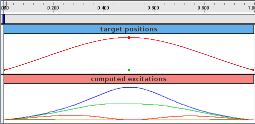
Probes are created to specify the target trajectory and record the computed excitations. The first, targetprobe, is an input probe attached to the position property of the target component, running from time 0 to 1 (lines 72-79). Its data is specified in code using addData(), which specifies three knot points with a time step of 0.5. Interpolation is set to cubic (line 78) for greater smoothness. The second, exprobe, is a probe that records all the excitations computed by the controller (lines 82-85). It is created by the utility method createOutputProbe() supplied by the InverseManager class (Section 10.4.1).
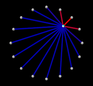
To run this example, select All demos > tutorial > InverseParticle from the Models menu. The model should load and initially appear as in Figure 10.3 (left). When run, the controller computes excitations to move the particle along the trajectory specified by the probe, which is upward and to the right (Figure 10.3, right) and back again.
The target point created by the controller is rendered separately from the source point as a cyan-colored sphere (see Section 10.2.2.2). As the simulation proceeds and certain muscles are excited, their coloring changes from blue to red, in proportion to their excitation, in accordance with the properties excitationColor and maxColoredExcitation. Recorded data for both the trajectory and the computed excitation probes are shown in Figure 10.4.
