A.1 Rotation transforms
Rotation matrices are used to describe the orientation of 3D coordinate frames in space, and to transform vectors between these coordinate frames.

Consider two 3D coordinate frames A and B that are rotated with
respect to each other (Figure A.1). The orientation
of B with respect to A can be described by a ![]() rotation
matrix
rotation
matrix ![]() , whose columns are the unit vectors giving the
directions of the rotated axes
, whose columns are the unit vectors giving the
directions of the rotated axes ![]() ,
, ![]() , and
, and ![]() of B with
respect to A.
of B with
respect to A.
![]() is an orthogonal matrix, meaning that
its columns are both of unit length and mutually
orthogonal, so that
is an orthogonal matrix, meaning that
its columns are both of unit length and mutually
orthogonal, so that
| (A.1) |
where ![]() is the
is the ![]() identity matrix. The inverse
of
identity matrix. The inverse
of ![]() is hence equal to its transpose:
is hence equal to its transpose:
| (A.2) |
Because ![]() is orthogonal,
is orthogonal, ![]() , and because it
is a rotation,
, and because it
is a rotation, ![]() (the other case, where
(the other case, where ![]() , is not a rotation but a reflection). The 6 orthogonality
constraints associated with a rotation matrix mean that in spite of
having 9 numbers, the matrix only has 3 degrees of freedom.
, is not a rotation but a reflection). The 6 orthogonality
constraints associated with a rotation matrix mean that in spite of
having 9 numbers, the matrix only has 3 degrees of freedom.
Now, assume we have a 3D vector ![]() , and consider its coordinates
with respect to both frames A and B. Where necessary, we use a
preceding superscript to indicate the coordinate frame with respect to
which a quantity is described, so that
, and consider its coordinates
with respect to both frames A and B. Where necessary, we use a
preceding superscript to indicate the coordinate frame with respect to
which a quantity is described, so that ![]() and
and ![]() denote
denote ![]() with respect to frames A and B, respectively. Given the
definition of
with respect to frames A and B, respectively. Given the
definition of ![]() given above, it is fairly straightforward to
show that
given above, it is fairly straightforward to
show that
| (A.3) |
and, given (A.2), that
| (A.4) |
Hence in addition to describing the orientation of B with respect to A,
![]() is also a transformation matrix that maps vectors in B
to vectors in A.
is also a transformation matrix that maps vectors in B
to vectors in A.
It is straightforward to show that
| (A.5) |

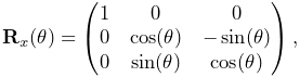
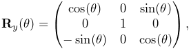
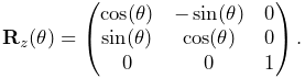
A simple rotation by an angle ![]() about one of the basic
coordinate axes is known as a basic rotation. The three
basic rotations about x, y, and z are:
about one of the basic
coordinate axes is known as a basic rotation. The three
basic rotations about x, y, and z are:
 |
 |
 |
Next, we consider transform composition. Suppose we have three
coordinate frames, A, B, and C, whose orientations are related to each other by
![]() ,
, ![]() , and
, and ![]() (Figure
A.2). If we know
(Figure
A.2). If we know ![]() and
and ![]() ,
then we can determine
,
then we can determine ![]() from
from
| (A.6) |
This can be understood in terms of vector transforms. ![]() transforms a vector from C to B, which is equivalent to first
transforming from C to A,
transforms a vector from C to B, which is equivalent to first
transforming from C to A,
| (A.7) |
and then transforming from A to B:
| (A.8) |
Note also from (A.5) that ![]() can be
expressed as
can be
expressed as
| (A.9) |
In addition to specifying rotation matrix components explicitly, there are numerous other ways to describe a rotation. Three of the most common are:
- Roll-pitch-yaw angles
-
There are 6 variations of roll-pitch-yaw angles. The one used in ArtiSynth corresponds to older robotics texts (e.g., Paul, Spong) and consists of a roll rotation
 about the z axis, followed by a pitch
rotation
about the z axis, followed by a pitch
rotation  about the new y axis, followed by a yaw rotation
  about the new x axis. The net rotation can be expressed by the
following product of basic rotations:
about the new x axis. The net rotation can be expressed by the
following product of basic rotations: 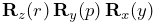 .
. - Axis-angle
-
An axis angle rotation parameterizes a rotation as a rotation by an angle
 about a specific axis
  . Any rotation
can be represented in such a way as a consequence of Euler’s rotation
theorem.
. Any rotation
can be represented in such a way as a consequence of Euler’s rotation
theorem. - Euler angles
-
There are 6 variations of Euler angles. The one used in ArtiSynth consists of a rotation
 about the z axis, followed by a rotation
about the new y axis, followed by a rotation
about the z axis, followed by a rotation
about the new y axis, followed by a rotation  about the
new z axis. The net rotation can be expressed by the following product
of basic rotations:
about the
new z axis. The net rotation can be expressed by the following product
of basic rotations: 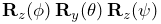 .
.
![[LOGO]](data:image/png;base64,iVBORw0KGgoAAAANSUhEUgAAAAsAAAAOCAYAAAD5YeaVAAAAAXNSR0IArs4c6QAAAAZiS0dEAP8A/wD/oL2nkwAAAAlwSFlzAAALEwAACxMBAJqcGAAAAAd0SU1FB9wKExQZLWTEaOUAAAAddEVYdENvbW1lbnQAQ3JlYXRlZCB3aXRoIFRoZSBHSU1Q72QlbgAAAdpJREFUKM9tkL+L2nAARz9fPZNCKFapUn8kyI0e4iRHSR1Kb8ng0lJw6FYHFwv2LwhOpcWxTjeUunYqOmqd6hEoRDhtDWdA8ApRYsSUCDHNt5ul13vz4w0vWCgUnnEc975arX6ORqN3VqtVZbfbTQC4uEHANM3jSqXymFI6yWazP2KxWAXAL9zCUa1Wy2tXVxheKA9YNoR8Pt+aTqe4FVVVvz05O6MBhqUIBGk8Hn8HAOVy+T+XLJfLS4ZhTiRJgqIoVBRFIoric47jPnmeB1mW/9rr9ZpSSn3Lsmir1fJZlqWlUonKsvwWwD8ymc/nXwVBeLjf7xEKhdBut9Hr9WgmkyGEkJwsy5eHG5vN5g0AKIoCAEgkEkin0wQAfN9/cXPdheu6P33fBwB4ngcAcByHJpPJl+fn54mD3Gg0NrquXxeLRQAAwzAYj8cwTZPwPH9/sVg8PXweDAauqqr2cDjEer1GJBLBZDJBs9mE4zjwfZ85lAGg2+06hmGgXq+j3+/DsixYlgVN03a9Xu8jgCNCyIegIAgx13Vfd7vdu+FweG8YRkjXdWy329+dTgeSJD3ieZ7RNO0VAXAPwDEAO5VKndi2fWrb9jWl9Esul6PZbDY9Go1OZ7PZ9z/lyuD3OozU2wAAAABJRU5ErkJggg==)