10.4 Managing probes and control panels
The tracking controller package provides the helper class InverseManager to aid with the creation of probes and control panels that are useful in for inverse simulation applications. The functionality provided by InverseManager is described in this section, and additional documentation may be found in its API documentation.
10.4.1 Inverse simulation probes
| ProbeID | I/O type | Probe name | Default filename |
|---|---|---|---|
| TARGET_POSITIONS | input | "target positions" | target_positions.txt |
| INPUT_EXCITATIONS | input | "input excitations" | input_excitations.txt |
| TRACKED_POSITIONS | output | "tracked positions" | tracked_positions.txt |
| SOURCE_POSITIONS | output | "source positions" | source_positions.txt |
| COMPUTED_EXCITATIONS | output | "computed excitations" | computed_excitations.txt |
InverseManager contains static methods that support the creation and management of a variety of probes related to inverse simulation. These probes are defined by the enumerated type InverseManager.ProbeID, which includes the following identifiers:
- TARGET_POSITIONS
-
A PositionInputProbe (Section 5.4.8) which provides a trajectory
 for all motion targets. Its input values
are attached to the position property of each point target and the position and orientation properties of each frame target, in the order
the targets appear in the controller. The rotation representation is given by
the positionProbeRotRep property of the controller.
for all motion targets. Its input values
are attached to the position property of each point target and the position and orientation properties of each frame target, in the order
the targets appear in the controller. The rotation representation is given by
the positionProbeRotRep property of the controller. - INPUT_EXCITATIONS
-
An input probe which provides input excitation values for all the controller’s exciters, in the order they appear in the controller. This probe can be used for testing purposes, in order to see what trajectory can be expected to arise from a given excitation input.
- TRACKED_POSITIONS
-
A PositionOutputProbe which records the positions of all motion targets as they are set by the controller. Its output values are extracted from the same component properties used by TARGET_POSITIONS, and its rotation representation is given by the positionProbeRotRep property of the controller.
- SOURCE_POSITIONS
-
A PositionOutputProbe which records the actual position trajectory
 followed by all motion sources. Its output values are
extracted from the same component properties used by TARGET_POSITIONS,
and its rotation representation is given by the positionProbeRotRep
property of the controller.
followed by all motion sources. Its output values are
extracted from the same component properties used by TARGET_POSITIONS,
and its rotation representation is given by the positionProbeRotRep
property of the controller. - COMPUTED_EXCITATIONS
-
An output probe which records the computed excitation values for all the controller’s exciters, in the order they appear in the controller.
Each of these probes is associated with both a name and a default file name (Table 10.1), where the default file name may be assigned if another file path is not explicitly specified.
When a default file name is used, it is assumed to be relative to the ArtiSynth working folder, as described in Section 5.4.
These probes may be created, for a given tracking controller, with the following (static) InverseManager methods:
| NumericInputProbe createInputProbe (TrackingController tcon, ProbeID pid, String filePath, double start, double stop) |
Create input probe specified by pid. |
| NumericOutputProbe createOutputProbe (TrackingController tcon, ProbeID pid, String filePath, double start, double stop, double interval) |
Create output probe specified by pid. |
Here pid specifies the probe type, filePath an (optional) file path, start and stop the start and stop times, and interval the output probe update interval.
Created probes may be added to the application root model as needed.
Most of the examples above use createOutputProbe() to create a computed excitations probe. In InverseMuscleFem (Section 10.2.5), the two output probes used to display the tracked position and orientation of myFrame, created at lines (42-51), could be replaced by a single probe of type SOURCE_POSITIONS, using a code fragment like this:
Likewise, a probe showing the target position and orientation, for purposes of comparing it against SOURCE_POSITIONS and evaluating the tracking error, could be created using
For both these method calls, the source and target components (myFrame and target in the example) are automatically located within the tracking controller.
If the created probe is a PositionInputProbe or PositionOutputProbe, and one needs access to the features of that type, a cast will be necessary, e.g.:
One reason to create a TRACKED_POSITIONS probe, instead of comparing SOURCE_POSITIONS directly against the trajectory input probe, is that the former is guaranteed to have the same number of data points as SOURCE_POSITIONS, whereas a trajectory probe, being an input probe, may not. Moreover, if the trajectory is being produced using a controller, a trajectory probe may not even exist.
For convenience, InverseManager also provides methods to add a complete set of default probes to the root model:
| void addProbes (RootModel root, TrackingController tcon, double duration, double interval) |
Add default probes to root. |
| void resetProbes (RootModel root, TrackingController tcon, double duration, double interval) |
Clear probes and add default probes to root. |
addProbes() creates a COMPUTED_EXCITATIONS probe and an INPUT_EXCITATIONS probe, with the latter deactivated by default. If the controller has any motion targets, it will also create TARGET_POSITIONS, TRACKED_POSITIONS and SOURCE_POSITIONS probes. Probe start times are set to 0, stop times are set to duration, and the output probe update interval is set to interval, with -1 causing the interval to default to the simulation step size. Probe file names are set to the default file names described in Table 10.1. Since these file names are relative, the files themselves are assumed to exist in the ArtiSynth working folder, as described in Section 5.4. If the file for an input probe actually exists, it is used to initialize the probe’s data; otherwise, the probe data is initialized to 0 and the probe is deactivated.
resetProbes() removes all existing probes and then behaves identically to addProbes().
InverseManager also supplies methods to locate and adjust the probes that it has created:
| NumericInputProbe findInputProbe ( RootModel root, ProbeID pid) |
Find specified input probe. |
| PositionInputProbe findPositionInputProbe ( RootModel root, ProbeID pid) |
Find input probe, restricted to PositionInputProbes. |
| NumericOutputProbe findOutputProbe ( RootModel root, ProbeID pid) |
Find specified output probe. |
| PositionOutputProbe findPositionOutputProbe ( RootModel root, ProbeID pid) |
Find output probe, restricted to PositionOutputProbes. |
| Probe findProbe (RootModel root, ProbeID pid) |
Find specified input or output probe. |
| boolean setInputProbeData (RootModel root, ProbeID pid, double[] data, double timeStep) |
Set input probe data. |
| boolean setProbeFileName (RootModel root, ProbeID pid, String filePath) |
Set probe file path. |
The findProbe() methods search for the probe specified by pid within a root model, using the probe’s file name (Table 10.1) as a search key. The method setInputProbeData() searches for a specified probe, and if it is found, sets its data using the probe’s setData(double[],double) method and returns true. Likewise, setProbeFileName() searches for a specified probe and sets its file path.
Since probes maintained by InverseManager use probe names as a search key, care should be taken to ensure that these names do not conflict with those of other application probes.
10.4.2 Example: using InverseManager probes
The example InverseMuscleArm (Section 10.2.4) has been configured for use with the InverseManager by setting its working folder to inverseMuscleArm located beneath its source folder. If instead of creating the target and output excitations probes (lines 34-52), addProbes() is simply called at the end of the build() method (after the working folder has been set), as in
then a set of probes will be created as shown in Figure 10.13. The tracing probes ("target tracing" and "source tracing") are still present, in addition to five default probes. TARGET_POSITIONS and INPUT_EXCITATIONS are expanded to show the data that has been automatically loaded from the files target_positions.txt and input_excitations.txt located in the working folder. By default, the former probe is enabled and the latter is disabled. If the model is run, inverse simulation will proceed as before.
After loading the probes, the application could disable the tracking controller and enable the input excitations:
This will cause the simulation to run “open loop” in response to the excitations. However, because the input excitations are slightly different than those that were computed by the controller, there is now a considerable tracking error (Figure 10.14, left).
After the open loop run, one can save the resulting SOURCE_POSITIONS probe, which will write the file "source_positions.txt'' into the working folder. This can then be used to generate a new target trajectory, by copying it to "target_positions.txt". If the model is reloaded, the new trajectory will now appear in the TARGET_POSITIONS probe (Figure 10.15). Deactivating the INPUT_EXCITATIONS probe and reactivating the tracking controller will cause this new trajectory to be tracked properly (Figure 10.14, right).
In ways such as this, the probes may be used to examine the behavior and performance of the tracking controller.
|
|
10.4.3 Inverse control panel
InverseManager also provide methods to create and manage an inverse control panel, which allows interactive editing of the properties of the tracking controller and its various cost terms, as described in Section 10.3. Applications can create an instance of this panel in their build() method, as the InverseMuscleArm example (Section 10.2.4) does at line 65:
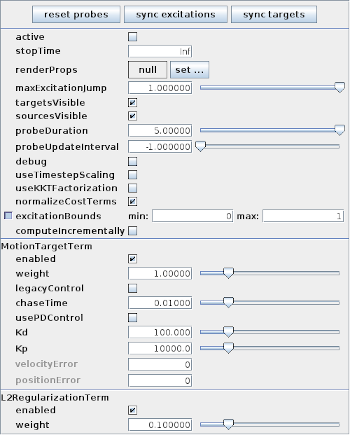
The panel is automatically configured to display the properties of the cost terms with which the controller is currently configured. Figure 10.16 shows the panel for InverseMuscleArm.
The following methods are supplied by InverseManager to manage inverse control panels:
| ControlPanel createInversePanel (TrackingController tcon) |
Create inverse control panel for tcon. |
| ControlPanel addInversePanel (RootModel root, TrackingController tcon) |
Create and add inverse control panel to root. |
| ControlPanel findInversePanel (RootModel root) |
Find inverse control panel in root. |
At the top of the inverse panel are three buttons: "reset probes", "sync excitations", and "sync targets". The first uses InverseManager.resetProbes() to clear all probes and recreate the default probes, using the duration and update interval specified by the tracking controller properties probeDuration and probeUpdateInterval. The second button copies the contents of the COMPUTED_EXCITATIONS probe into the INPUT_EXCITATIONS probe. If this is done after excitations have been computed, then running the simulation again with the controller deactivated and INPUT_EXCITATIONS activated should produce an identical motion. The third button copies the contents of the SOURCE_POSITIONS probe into the TARGET_POSITIONS. This can be used to verify that a source trajectory created open loop with a prescribed set of input excitations can in fact be tracked by the controller.
The probe copy methods used by the “sync” buttons are also available to the application code:
| boolean syncTargetProbes (RootModel root) |
Copy SOURCE_POSITIONS into TARGET_POSITIONS. |
| boolean syncExcitationProbes (RootModel root) |
Copy COMPUTED_EXCITATIONS into INPUT_EXCITATIONS. |
![[LOGO]](data:image/png;base64,iVBORw0KGgoAAAANSUhEUgAAAAsAAAAOCAYAAAD5YeaVAAAAAXNSR0IArs4c6QAAAAZiS0dEAP8A/wD/oL2nkwAAAAlwSFlzAAALEwAACxMBAJqcGAAAAAd0SU1FB9wKExQZLWTEaOUAAAAddEVYdENvbW1lbnQAQ3JlYXRlZCB3aXRoIFRoZSBHSU1Q72QlbgAAAdpJREFUKM9tkL+L2nAARz9fPZNCKFapUn8kyI0e4iRHSR1Kb8ng0lJw6FYHFwv2LwhOpcWxTjeUunYqOmqd6hEoRDhtDWdA8ApRYsSUCDHNt5ul13vz4w0vWCgUnnEc975arX6ORqN3VqtVZbfbTQC4uEHANM3jSqXymFI6yWazP2KxWAXAL9zCUa1Wy2tXVxheKA9YNoR8Pt+aTqe4FVVVvz05O6MBhqUIBGk8Hn8HAOVy+T+XLJfLS4ZhTiRJgqIoVBRFIoric47jPnmeB1mW/9rr9ZpSSn3Lsmir1fJZlqWlUonKsvwWwD8ymc/nXwVBeLjf7xEKhdBut9Hr9WgmkyGEkJwsy5eHG5vN5g0AKIoCAEgkEkin0wQAfN9/cXPdheu6P33fBwB4ngcAcByHJpPJl+fn54mD3Gg0NrquXxeLRQAAwzAYj8cwTZPwPH9/sVg8PXweDAauqqr2cDjEer1GJBLBZDJBs9mE4zjwfZ85lAGg2+06hmGgXq+j3+/DsixYlgVN03a9Xu8jgCNCyIegIAgx13Vfd7vdu+FweG8YRkjXdWy329+dTgeSJD3ieZ7RNO0VAXAPwDEAO5VKndi2fWrb9jWl9Esul6PZbDY9Go1OZ7PZ9z/lyuD3OozU2wAAAABJRU5ErkJggg==)