4 Component Navigation and Selection
An ArtiSynth model is composed of a hierarchical arrangement of model components (each of which implements the interface ModelComponent), some of which may themselves be models. The graphical interface allows users to navigate this hierarchy and select individual components. Selected components can then be edited, or have specific properties modified or attached to probes or control panels.
4.1 The component hierarchy
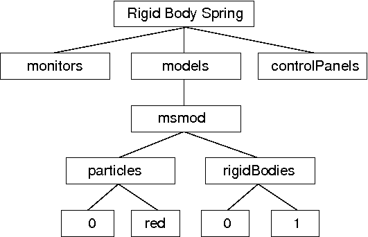
An example component hierarchy is shown in Figure 16. At the top is a root model (class RootModel), in this case named Rigid Body Spring. The root model in turn contains a list of models, one of which is a mechanical model named msmod, which here contains particles and rigid bodies.
It is important to node that in the component hierarchy, any collection of components is itself a component (usually an instance of ComponentList). This provides automatic “grouping” of components of like type, but does introduce additional levels into the hierarchy. Hence the particle red is a child not of msmod, but rather the component list particles.
4.1.1 Component names and numbers
Model components may be assigned a string name; at the time of this writing names may not begin with a digit, have zero length, contain the characters ‘.’ or ‘/’, or equal the reserved word this. Components which do not have an assigned name are called nameless.
All components have a number, even if they do not have a name. The number is assigned automatically when the component is added to the parent, and is guaranteed to be persistent until the component is removed from the parent.
4.1.2 Component path names
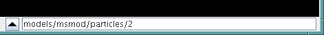
The names and/or numbers of a component’s ancestors can be used to form a component path name. This path has a construction completely analogous to Unix file path names, with the ‘/’ character acting as a separator. Absolute paths start with ‘/’ and begin with the root model. Relative paths omit the leading ‘/’ and can begin lower down in the hierarchy. The absolute path name of the red particle in Figure 16 would be
/Rigid Body Spring/models/msmod/particles/red
For nameless components in the path, their numbers can be used instead:
/Rigid Body Spring/models/msmod/rigidBodies/1
Numbers can be used even for components that have names. Hence a path name consisting only of numbers, as in
/0/0/0/3/1
is legal, although it most likely to appear only in machine-generated output.
4.2 Navigation panel selection
A navigation panel in the main ArtiSynth frame allows direct
navigation of the component hierarchy. The panel can be
open or closed by clicking on the main toolbar icon
![]() .
.
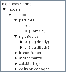
Left clicking on any component in the navigation panel selects that component. Clicking while pressing the CTRL key (or the CMD key on some platforms, such as Mac) allows selection of multiple components. Clicking while pressing the SHIFT key allows selection of a range of components.
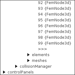
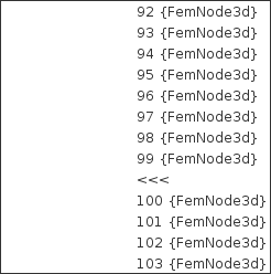
4.2.1 Large numbers of nameless components
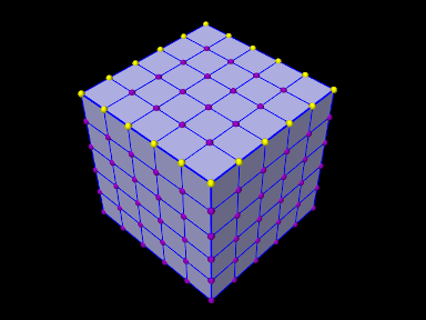
In some cases, such as finite element models, the number of child components can be very large (on the order of thousands). In order to keep the navigation panel size manageable, the number of nameless children displayed is limited to a set number (currently 100). If the number of nameless children exceeds this number, the display will be augmented with an expand icon >>>. Clicking on this will expand the display to include all nameless components, and the expand icon will be replaced by a contract icon <<<. Clicking on the contract icon will cause the extra nameless components to be hidden again. This is illustrated in Figure 18.
 |
 |
4.3 Viewer selection
Components that are rendered in the viewer can generally be selected by variety of methods (the exception is for a few renderable components that do not support selection). These methods include click, box, and elliptic selection. The top two icons in the selection toolbar at the left of the ArtiSynth frame control the current selection method. In addition, hitting the ‘c’ key from within the viewer (Section 3.12) clears the current selection.
4.3.1 Click and box selection
Click and box selection are enabled by the arrow icon at the top of the selection toolbar:
Click selection involves left clicking on a component, causing it to be selected. Selection of multiple components is enabled by left clicking with a modifier key, which is usually CTRL but may be different for some legacy mouse bindings (Section 3.11).
Click selection selects only those components which are actually visible to the viewer; components which are hidden cannot be selected this way.
Box selection is effected by left-clicking and dragging in the viewer, causing the selection of all components rendered within the resulting drag box. Because this often results in the selection of more components than desired, it may be useful to employ a selection filter (Section 4.3.3). Any components within the drag box which are already selected will be deselected.
Box selection acts on all (filtered) components within the view frustum defined by the drag box, including those which are hidden from view.
4.3.2 Elliptic selection
Elliptic selection is enabled by the elliptic icon near the top of the selection toolbar:
This causes an additional elliptic cursor (which defaults to a circle) to be drawn around the mouse cursor. Selection is effected by dragging, and causes all visible objects within the ellipse to be selected. The selection process is cumulative, with subsequent drags selecting additional components. As with all selection operations, a filter can be set to restrict the components that are selected (Section 4.3.3). Generally, the drag select operation requires no modifier keys, although it may with some legacy mouse bindings (Section 3.11).
It is also possible to deselect components in the same way, by using the SHIFT modifier key to cause drag operations to cumulatively deselect components.
Elliptic selection selects only those components which are actually visible to the viewer; components which are hidden cannot be selected this way.
The elliptic cursor used for selection can be resized, either interactively, or by setting the ellipticCursorSize property of the viewer (Section 3.10). To interactively change the cursor size, initiate a drag operation with the CTRL and SHIFT modifiers. Finally, the ‘d’ key shortcut within the viewer will cause the cursor to be reset to its default size.
4.3.3 Selection filtering
It is possible to limit viewer selection to components of a specific type. This can be done using the selection filter widget at the bottom left of the main ArtiSynth frame Figure 19.
To enable filtering, type into the widget text box the class name of the component type you wish to restrict filtering to. It is generally only necessary to enter the leaf name of the class (e.g., Particle or AxialSpring), and the system will then find the full class name by searching the ArtiSynth class path.
Once filtering is enabled, only components which are instances (including subclasses) of the specified type will be selectable.
Previously selected filters can be recalled using a history list accessible using the leftmost arrow button on the selection widget.
To remove selection filtering, enter the special filter *, either by typing this in the text box, or using the history list.
4.4 Selection display
The selection display Figure 20 at the bottom of the main ArtiSynth frame shows the full path name of the last component added to the selection list. This is useful for identifying components in detail.
If no components are selected, then the selection display is blank.
The selection display is useful for disambiguating situations where it is not clear what component we have actually selected in the viewer. For example, FEM models keep their surface mesh contained within a descendant component. Selecting the surface mesh will cause this container component to be selected and highlighted, making it appear as though the FEM model itself is selected rather than the container. Checking the selection display makes it clear what component has actually been selected. If desired, one can easily navigate to one of the ancestor components using parent selection, as described in the next section.
4.5 Selecting parent and ancestor components
Sometimes, when you select a component, you actually want to select one of it’s ancestor components.
There are several ways to do this:
-
1.
Hit the escape (ESC) key within the viewer window. This will select the parent of the currently selected component. Hitting escape repeatedly is a fast way to proceed up the component hierarchy.
-
2.
Click on the “up” arrow located at the left of the selection display (Figure 20). This will also select the parent of the currently selected component.
Parent selection is particularly useful in the commonly occurring situation where a composite component is not rendered and therefore not selectable in the viewer. For instance, suppose we wish to select a FEM model. One can select any renderable descendant of the model, such as a node, element, or its surface mesh (if displayed), and then use repeated parent selection until the model itself is selected.
4.6 Highlighting selected components
Selected components are rendered in the viewer using a special selection color (yellow at the time of this writing). It is important to note that descendants of a selected component are not presently rendered in any special way. For instance, if an FEM is selected, it’s nodes and elements will be rendered normally.
While this has the potential to be confusing, we have not yet found this to be problematic, as the navigation panel and selection display provide alternative indicators as to what is currently selected.
4.7 Selecting FEM nodes
A specialized tool is available for selecting FEM nodes, because it is often necessary to identify collections of nodes for connecting to rigid bodies or other FEM models, or to set localized properties and/or boundary conditions.
 |
 |
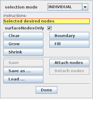
To open the node selection tool, first select the FEM model containing the nodes, and then invoke the context menu (usually via right-click) and choose “Select nodes ...”. A node selection tool will appear, as shown in Figure 21. From top to bottom, this contains several controls:
-
1.
A selection mode chooser that specifies how nodes are selected, possibly followed by mode-specific fields to adjust the selection behavior;
-
2.
An instruction box describing what action the user should take;
-
3.
A surfaceNodesOnly check box that allows selected nodes to be restricted to the FEM model’s surface;
-
4.
Buttons for clearing, growing or shrinking the selection, reducing the selection to its boundary, or for filling it in;
-
5.
Buttons for saving/loading a list of the selected nodes to/from a file, or for attaching or detaching selected nodes from other bodies.
While a node selection tool is open, GUI selections are restricted to certain components, usually nodes of the indicated FEM model. If surfaceNodesOnly is checked, selection is restricted to the FEM surface nodes. Selection is also held in a “multiple component” mode, equivalent to holding down the multiple selection key (usually CTRL), so that the selection can be easily edited and is not reset with each selection action.
 |
 |
The different selection modes and their parameters include:
- INDIVIDUAL
-
- PATCH
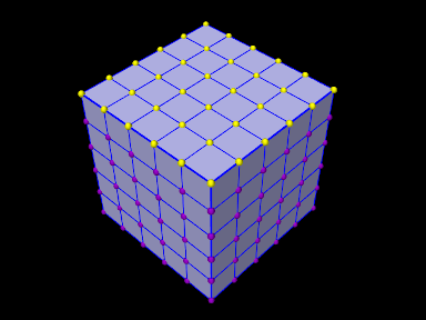
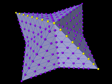
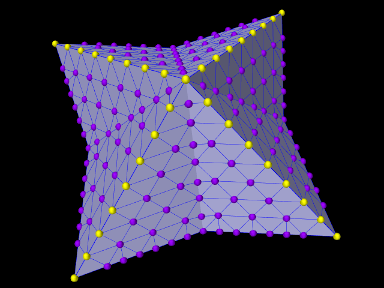
-
Nodes are selected, on the mesh surface, within a patch region defined by a set of faces for which the bend angle between adjacent faces is less than or equal to a specified maximum bend angle. The bend angle is defined as the absolute value of the angle between two faces along their common edge, such that parallel faces have a bend angle of
 and perpendicular ones have a bend
angle of
and perpendicular ones have a bend
angle of  . Within the tool, the maximum bend angle is
specified (in degrees) by the field maxBendAngle. To find the
patch nodes, the user selects a node within the desired patch
area. Starting with the node’s adjacent faces, the patch is then grown
outwards to find all neighboring faces such that the bend angle
between them does not exceed maxBendAngle (Figure
22, left).
. Within the tool, the maximum bend angle is
specified (in degrees) by the field maxBendAngle. To find the
patch nodes, the user selects a node within the desired patch
area. Starting with the node’s adjacent faces, the patch is then grown
outwards to find all neighboring faces such that the bend angle
between them does not exceed maxBendAngle (Figure
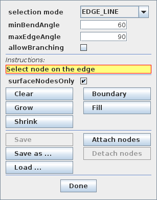
22, left). - EDGE_LINE
-
Nodes are selected, on the mesh surface, along an edge line defined by faces meeting at a bend angle greater than or equal to a specified minimum bend angle. Within the tool, this minimum angle is specified (in degrees) by the field minBendAngle. To find edge line nodes, the user selects a node lying along the desired edge line. The line is then followed from node to node, by locating edges with a large enough bend angle.
EDGE_LINE selection is illustrated in Figure 23, and the following fields adjust its behavior:
- minBendAngle
-
Minimum bend angle, described above.
- maxEdgeAngle
-
Specifies (in degrees) the maximum edge angle between two adjacent edges along the edge line. Line following is terminated when the angle between the current edge and the next edge exceeds this threshold.
- allowBranching
-
If selected, allows the edge line to branch in different directions. Otherwise, edges are followed sequentially so as to minimize the edge angle between them.
- DISTANCE
-
Nodes are selected based on being within a prescribed distance of a polygonal mesh, which may be the surface mesh for a rigid body or FEM model, or some other mesh component. The distance threshold is specified by the field distance. To select nodes, the user may select any mesh component containing a polygonal mesh. The user may also select a rigid body or FEM model, which will cause the body’s surface mesh to be used for the distance calculation.
The following fields adjust the behavior of DISTANCE selection:
- distance
-
Distance threshold, described above.
- useSignedDistance
-
If selected, causes the distance computation for closed meshes to be signed, so that nodes inside the mesh will have a negative distance. This means that for a non-negative distance threshold, nodes inside the mesh will always be selected.
- surfaceNodesOnly
-
If checked, the selection is restricted to the FEM model’s surface.
- MINIMUM_PATH
-
In this mode, the user selects an individual node, and the tool then selects a minimum path of nodes between it and the previously selected node. This is particularly useful for “drawing” the boundary of a nodal region on the FEM model’s surface.
If surfaceNodesOnly is checked, the path will be restricted to the FEM surface; otherwise, the path may proceed through the FEM interior.
When forming the path, the tool chooses from adjacent nodes based on the topology induced by the FEM elements. This can sometimes lead to a path that is less minimal than if nodes could be chosen arbitrarily, particularly for quadratic hex, wedge and pyramid elements.
 |
 |
The user is free to change modes during the selection process. Because selection is held in multiple selection mode, it is easy to edit the selection. In particular, INDIVIDUAL selection can be used for fine editing of selections obtained using PATCH, EDGE_LINE, DISTANCE, or MINIMAL_PATH.
Below the surfaceNodesOnly check box, the tool contains a number of buttons:
- Clear
-
Unselects all the nodes.
- Grow
-
Enlarges the current selection to include adjacent nodes.
- Shrink
-
Reduces the current selection by removing nodes on the boundary.
- Boundary
-
Reduces the current selection to include only its boundary nodes (Figure 22, right).
- Fill
-
Fills a region in the current selection. After clicking this button, the user selects a node inside the desired region. The selection is then grown outward from the selected node until it reaches the region’s boundary.
- Attach nodes
-
Attaches the selected nodes to another body which is either a rigid body or an FEM model. The body may be chosen by selecting it directly, or by selecting one of its component meshes. Nodes which are currently attached are not attached to the body.
- Detach nodes
-
Detaches all selected nodes from any body or particle that they are currently attached to.
- Save
-
Saves the nodes to a file that has been previously specified using either “Save as ...” or “Load ...”.
- Save as ...
-
Saves the nodes to a user-specified text file. The format consists simply of integer node numbers (with respect to the selection tool’s FEM model), separated by white space. More details on the file format are given in the section “Selecting nodes in the viewer” of the ArtiSynth Modeling Guide.
- Load ...
-
Loads the selected nodes from a text file, the format for which is described under “Save as ...”.
![[LOGO]](data:image/png;base64,iVBORw0KGgoAAAANSUhEUgAAAAsAAAAOCAYAAAD5YeaVAAAAAXNSR0IArs4c6QAAAAZiS0dEAP8A/wD/oL2nkwAAAAlwSFlzAAALEwAACxMBAJqcGAAAAAd0SU1FB9wKExQZLWTEaOUAAAAddEVYdENvbW1lbnQAQ3JlYXRlZCB3aXRoIFRoZSBHSU1Q72QlbgAAAdpJREFUKM9tkL+L2nAARz9fPZNCKFapUn8kyI0e4iRHSR1Kb8ng0lJw6FYHFwv2LwhOpcWxTjeUunYqOmqd6hEoRDhtDWdA8ApRYsSUCDHNt5ul13vz4w0vWCgUnnEc975arX6ORqN3VqtVZbfbTQC4uEHANM3jSqXymFI6yWazP2KxWAXAL9zCUa1Wy2tXVxheKA9YNoR8Pt+aTqe4FVVVvz05O6MBhqUIBGk8Hn8HAOVy+T+XLJfLS4ZhTiRJgqIoVBRFIoric47jPnmeB1mW/9rr9ZpSSn3Lsmir1fJZlqWlUonKsvwWwD8ymc/nXwVBeLjf7xEKhdBut9Hr9WgmkyGEkJwsy5eHG5vN5g0AKIoCAEgkEkin0wQAfN9/cXPdheu6P33fBwB4ngcAcByHJpPJl+fn54mD3Gg0NrquXxeLRQAAwzAYj8cwTZPwPH9/sVg8PXweDAauqqr2cDjEer1GJBLBZDJBs9mE4zjwfZ85lAGg2+06hmGgXq+j3+/DsixYlgVN03a9Xu8jgCNCyIegIAgx13Vfd7vdu+FweG8YRkjXdWy329+dTgeSJD3ieZ7RNO0VAXAPwDEAO5VKndi2fWrb9jWl9Esul6PZbDY9Go1OZ7PZ9z/lyuD3OozU2wAAAABJRU5ErkJggg==)