2.2 Viewers
This section summarizes viewer functionality as defined by the Viewer interface. Note that specific viewer implementations may provide significant additional functionality, such as interactive view control, keyboard and mouse event handling, or graphical fixtures such as coordinate axes, grids or transformers. The description of these extra features is beyond the scope of this document.
Rendering is triggered within a viewer by calling its rerender() method, which then initiates two rendering steps:
-
1.
prerendering: The viewer calls the prerender() method for all its renderables, and adds those which are visible into a render list;
-
2.
repainting: All components in the render list are redrawn using their render() method;
Another viewer method, repaint(), can subsequently be called to initiate repainting without invoking prerendering.
In general, rerender() should be called whenever there is a change in the graphical state of the renderables. This includes changes in geometry, color, or visibility. In the context of simulation, rerender() should be called after every simulation step.
Otherwise, repaint() should be called when the graphical state of the scene has not changed but the final screen display has, such as when the viewpoint is changed, or the display window is unhidden or resized. This is more efficient than calling rerender() because it avoids the overhead of the prerendering step.
The prerendering step is invoked directly within the rerender() method, whereas the repainting step is called in whatever thread implements the graphical display. Since, as described below, one of the functions of the prerendering step is to cache rendering information, rerender() should be called in synchronization with both the graphical display thread and whatever thread(s) (such as a simulation thread) might be altering the state of the renderables.
2.2.1 Render lists
A render list is implemented by the class RenderList and sorts renderable components into separate sublists depending on whether they are primarily opaque, transparent, 2d opaque, and 2d transparent. These designations are determined by examining the flags returned by the renderable’s getRenderHints() method, with TWO_DIMENSIONAL indicating a two dimensional component and TRANSPARENT indicating a transparent one. These sublists assist the viewer in rendering a scene more realistically. For example, in OpenGL, better results are obtained if opaque objects are drawn before transparent ones, and two dimensional objects are drawn after three dimensional ones, with the depth buffer disabled.
A viewer maintains its own internal render list, and rebuilds it once during every prerendering step, using the following algorithm:
The list’s addIfVisible() method calls the component’s prerender() method, and then adds it to the appropriate sublist if it is visible:
A renderable’s visibility is determined as follows:
-
•
Any object implementing IsRenderable is visible by default.
-
•
If the object also implements HasRenderProps (as described in Section 2.3.9), then it is visible only if the RenderProps returned by getRenderProps() is non-null and the associated visible property is true.
As discussed in Section 2.2.3, a viewer can also be provided with an external render list, which is maintained by the application. It is the responsbility of the application, and not the viewer, to rebuild the external render list during the prerendering step. However, in the repainting step, the viewer will handle the redrawing of all the components in both its internal and external render lists.
2.2.2 Prerendering and Rendering
Prerendering allows renderables to
-
1.
update data structures anc cached data needed for rendering
-
2.
add additional renderables to the render list.
The caching of graphical state is typically necessary when rendering is performed in a thread separate from the main application, which can otherwise cause synchronization and consistency problems for renderables which are changing dynamically. For example, suppose we are simulating the motion of two objects, A and B, and we wish to render their positions at a particular time t. If the render thread is allowed to run in parallel with the thread computing the simulation, then A and B might be drawn with positions corresponding to different times (or worse, positions which are indeterminate!).
Synchronizing the rendering and simulation threads will aleviate this problem, but that means foregoing the speed improvement of allowing the rendering to run in parallel. Instead, renderables can use the prerender() method to cache their current state for later use in the render() method, in a manner analagous to double buffering. For example, suppose a renderable describes the position of a point in space, inside a member variable called myPos. Then its prerender() method can be constructed to save this into another another member variable myRenderPos for later use in render():
In the example above, the cached value is stored using floating point values, since this saves space and usually provides sufficient precision for rendering purposes.
As described in Section 2.4, objects can sometimes make use of render objects when rendering themselves. These can result in improved graphical efficieny, and also provide an alternate means for caching graphical information. If render objects are being used, it is recommmended that they be created or updated within prerender().
The prerender() method can also be used to add additional renderables to the render list. This is done by recursively calling the list’s addIfVisible() method. For example, if a renderable has two subcomponents, A and B, which also need to be rendered, then it can add them to the render list as follows:
In addition to adding A and B to the render list if they are visible, addIfVisible() will also call their prerender() methods, which will in turn give them the opportunity to add their own sub components to the render list. Note that prerender() is always called for the specified renderable, whether it is visible (and added to the list) or not (since even if a renderable is not visible, it might have subcomponents which are). This allows an entire hierarchy of renderables to be rendered by simply adding the root renderable to the viewer.
Note that any renderables added to the render list within prerender() are not added to the primary list of renderables maintained by the viewer.
Because of the functionality outlined above, calls to prerender() methods, and the viewer rerender() method that invokes them, should be synchronized with both the graphical display thread and whatever thread(s) might be altering the state of the renderables.
As indicated above, actual object rendering is done within its render() method, which is called during the repaint step, within whatever thread is responsible for graphical display. The render() method signature,
provides a Renderer interface (Section 2.3) which the object uses to draws itself, along with a flags argument that specifies additional rendering conditions. Currently only one flag is formally supported, Renderer.HIGHLIGHT, which requests that the object be rendered using highlighting (see Section 2.3.3.1).
2.2.3 Viewer renderables and external render lists
Renderables can be added or removed from a viewer using the methods
If renderables are arranged in a hierarchy, and add their own subcomponents to the render list during prerender(), as described in Section 2.2.2, then it may only be necessary to add top level renderable components to the viewer.
It is also possible to assign a viewer an external render list, for which the prerendering step is maintained by the application. This is useful in situations where multiple viewers are being used to simultaneously render a common set of renderables. In such cases, it would be wasteful for each viewer to repeatedly execute the prerender phase on the same renderable set. It may also lead to inconsistent results, if the state of renderables changes between different viewers’ invocation of the prerender phase.
To avoid this problem, an application may create its own render list and then give it to multiple viewers using setExternalRenderList(). A code sample for this is as follows:
The statement synchronize(extlist) ensures that calls to extlist.addIfVisible(r) (and the subsequent internal calls to prerender()) are synchronized with render() method calls made by the viewer. This works because the viewer also wraps its usage of extlist inside synchronize(extlist) statements.
Once the viewers have been assigned an external render list, they will handle the repainting step for its renderables, along with their own internal renderables, every time repainting is invoked through a call to either rerender() (as in the above example) or repaint().
2.2.4 Coordinate frames and view point control
A viewer maintains three primary coordinate frames for describing the relative locations and orientations of scene objects and the observing “eye” (or camera). These are the eye, model, and world frames.
The eye frame (sometimes also known as the camera frame) is a
right-handed frame located at the eye (or camera) focal point, with
the ![]() axis pointing toward the observer. The viewing frustum
is located in the half space associated with the negative
axis pointing toward the observer. The viewing frustum
is located in the half space associated with the negative ![]() axis of
the eye frame (and usually centered on said axis), with the near and
far clipping planes designated as the view plane and far
plane, respectively. The viewer also maintains a viewing center, typically located along the negative
axis of
the eye frame (and usually centered on said axis), with the near and
far clipping planes designated as the view plane and far
plane, respectively. The viewer also maintains a viewing center, typically located along the negative ![]() axis, and which
defines the point about which the camera pivots in response to
interactive view rotation.
axis, and which
defines the point about which the camera pivots in response to
interactive view rotation.
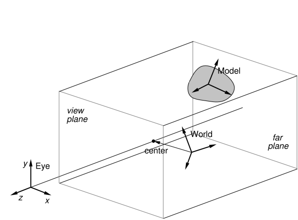
The viewing frustum is defined by the view and far planes, in combination with a projection matrix that transforms eye coordinates into clip coordinates. Most commonly, the projection matrix is set up for perspective viewing (Figure 2.3), but orthographic viewing (Figure 2.4) is sometimes used as well.
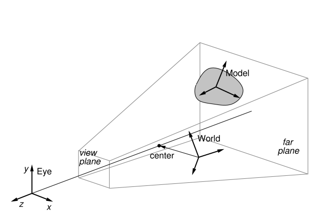
The model frame is the coordinate frame in which geometric
information for rendered objects is specified, and the world frame is the
base with respect to which the model and eye frames are defined. The
model matrix is the ![]() homogeneous affine transform
homogeneous affine transform
![]() from model to world coordinates, while the view matrix
is a
from model to world coordinates, while the view matrix
is a ![]() homogeneous rigid transform
homogeneous rigid transform ![]() from world to eye
coordinates. The composition of
from world to eye
coordinates. The composition of ![]() and
and ![]() transforms a
point from model coordinates
transforms a
point from model coordinates ![]() into eye coordinates
into eye coordinates ![]() ,
according to:
,
according to:
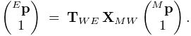 |
Note: the renderer assumes that points and vectors are column-based and the coordinate transforms work by pre-multiplying these column vectors. This is in constrast to some computer graphics conventions in which vectors are row based. Our transformation matrices are therefore the transpose of those defined with respect to a row-based convention.
Initially the world and model frames are coincident, so that ![]() . Rendering methods often redefine the model matrix, allowing
existing object geometry or built-in drawing methods to be used at
different scales and poses throughout the scene. The methods
available for querying and controlling the model matrix are described
in Section 2.3.8.
. Rendering methods often redefine the model matrix, allowing
existing object geometry or built-in drawing methods to be used at
different scales and poses throughout the scene. The methods
available for querying and controlling the model matrix are described
in Section 2.3.8.

Meanwhile, changing the view matrix allows the scene to be observed from different view points. A viewer provides the following direct methods for setting and querying the view matrix:
where
RigidTransform3d is defined
in maspack.matrix and represents a ![]() homogenous
rigid transformation.
Instead of specifying the view matrix, it is sometimes more convenient
to specify its inverse, the eye-to-world transform
homogenous
rigid transformation.
Instead of specifying the view matrix, it is sometimes more convenient
to specify its inverse, the eye-to-world transform ![]() .
This can be done with
.
This can be done with
where
Point3d and
Vector3d are also defined in
maspack.matrix and represent 3 dimensional points and vectors.
The method
setEyeToWorld(eye,center,up) sets ![]() according to legacy
OpenGL conventions so that (with respect to world coordinates) the eye
frame’s origin is defined by the point eye, while its
orientation is defined such that the
according to legacy
OpenGL conventions so that (with respect to world coordinates) the eye
frame’s origin is defined by the point eye, while its
orientation is defined such that the ![]() axis points from eye
to center and the
axis points from eye
to center and the ![]() axis is parallel to up (see Figure
2.5).
axis is parallel to up (see Figure
2.5).
Point3d is a subclass of Vector3d used to describe points in space. The only difference between the two is that they transform differently in response to rigid transforms (described by RigidTransform3d) or affine transforms (described by AffineTransform3d): point transformations include the translational component, while vector transformations do not.
The viewer also maintains a center position and an up
vector that are used to modify ![]() in conjunction
with the following:
in conjunction
with the following:
Again with respect to world coordinates, setEye(eye) sets the origin of the eye frame while recomputing its orientation from the current values of center and up, while setCenter(center) and setUpVector(up) set center and up and recompute the eye frame’s orientation accordingly.
It is also possible to specify axis-aligned views, so that the axes of the eye frame are exactly aligned with the axes of the world frame. This can be done using
setAxialView() sets the rotational
component of ![]() to REW, and moves the eye position so
that the viewer’s center lies along the new
to REW, and moves the eye position so
that the viewer’s center lies along the new ![]() axis. It also
sets the up vector to the
axis. It also
sets the up vector to the ![]() axis of REW, and stores REW as the viewer’s nominal axial view which can be used for
determining default orientations for fixtures such as grids.
AxisAlignedRotation defines 24 possible
axis-aligned orientations, and so there are 24 possible axis-aligned
views. Some of those commonly used in association with setAxialView() are:
axis of REW, and stores REW as the viewer’s nominal axial view which can be used for
determining default orientations for fixtures such as grids.
AxisAlignedRotation defines 24 possible
axis-aligned orientations, and so there are 24 possible axis-aligned
views. Some of those commonly used in association with setAxialView() are:
| X_Y | eye frame and world frame have the same orientaion |
|---|---|
| X_Z | eye frame |
| Y_Z | eye frame |
There are several methods available to reset the viewing frustum:
The setPerspective methods create a perspective-based frustum
(Figure 2.3). The first methods explicitly sets
the left, right, bottom and top edges of the view plane, along with
the (positive) distances to the near (i.e., view) and far planes,
while the second method creates a frustum centered on the ![]() axis,
using a specified vertical field of view. The setOrthogonal
methods create an orthographic frustum (Figure 2.4)
in a similar manner.
axis,
using a specified vertical field of view. The setOrthogonal
methods create an orthographic frustum (Figure 2.4)
in a similar manner.
Information about the current frustum can be queried using
For convenience, the viewer can also automatically determine appropriate values for the center and eye positions, and then fit a suitable viewing frustum around the scene. This is done using the renderables’ updateBounds() method to estimate a scene center and radius, along with the current value of the up vector to orient the eye frame. The auto-fitting methods are:
These auto-fit methods also make use of a default vertical field-of-view, which is initially 35 degrees and which can be controlled using
Finally, the viewer’s background color can be controlled using
2.2.5 Lights
Viewers also maintain scene lighting. Typically, a viewer will be initialized to a default set of lights, which can then be adjusted by the application. The existing light set can be queried using the methods
where Light is a class
containing parameters for the light.
Lights are described using the same parameters as those of OpenGL,
as described in Chapter 5 of the OpenGL Programming Guide (Red book).
Each has a position ![]() and (unit) direction
and (unit) direction ![]() in space, a type, colors associated with ambient, specular and diffuse lighting,
and coefficients for its attenuation formula. The attenuation formula
is
in space, a type, colors associated with ambient, specular and diffuse lighting,
and coefficients for its attenuation formula. The attenuation formula
is
where ![]() is the light intensity,
is the light intensity, ![]() is the distance between the
light and the point being lit, and
is the distance between the
light and the point being lit, and ![]() ,
, ![]() , and
, and ![]() are the constant,
linear and quadratic attentuation factors.
are the constant,
linear and quadratic attentuation factors.
Spot lights have the same properties as other lights, in addition to
also having a cutoff angle ![]() and an exponent
and an exponent ![]() .
The cutoff angle is the angle between the direction of the light and
the edge of its cone, while the exponent, whose default value is 0, is
used to determine how focused the light is. If
.
The cutoff angle is the angle between the direction of the light and
the edge of its cone, while the exponent, whose default value is 0, is
used to determine how focused the light is. If ![]() is the unit
direction from the light to the point being lit, and if
is the unit
direction from the light to the point being lit, and if ![]() , then the point being lit is within
the light cone and the light intensity
, then the point being lit is within
the light cone and the light intensity ![]() in the above equation is
multiplied by the spotlight effect, given by
in the above equation is
multiplied by the spotlight effect, given by
Since ![]() , a value of
, a value of ![]() gives
the least light reductuon, while valuse of
gives
the least light reductuon, while valuse of ![]() increase the
intensity of the spot light towards its center.
increase the
intensity of the spot light towards its center.
Information for a specific light is provided by a Light object, which contains the following fields:
- enabled
-
A boolean describing whether or not the light is enabled.
- type
-
An instance of Light.LightType describing the type of the light. Current values are DIRECTIONAL, POINT, and SPOT.
- position
-
A 3-vector giving the position of the light in world coordinates.
- direction
-
A 3-vector giving the direction of the light in world coordinates.
- ambient
-
RGBA values for the ambient light color.
- diffuse
-
RGBA values for the diffuse light color.
- specular
-
RGBA values for the specular light color.
- constantAttenuation
-
Constant term C in the attenuation formula
- linearAttenuation
-
Linear term L in the attenuation formula
- quadraticAttenuation
-
Quadratic term Q in the attenuation formula
- spotCosCutoff
-
For spotlights, the cosine of the cutoff angle
 .
. - spotExponent
-
For spotlights, the exponent
 .
.
Each of these fields is associated with accessor methods inside Light.
An application can also add or remove lights using
To create a new light, the application instantiates a Light object, sets the appropriate fields, and then calls addLight(). Lights can be removed either by reference to the light object or its index.
Lights are updated by the viewer at the beginning of each repaint step. That means that for lights already added to the viewer, any changes made to the fields of the associated Light object will take effect at the beginning of the next repaint step.
![[LOGO]](data:image/png;base64,iVBORw0KGgoAAAANSUhEUgAAAAsAAAAOCAYAAAD5YeaVAAAAAXNSR0IArs4c6QAAAAZiS0dEAP8A/wD/oL2nkwAAAAlwSFlzAAALEwAACxMBAJqcGAAAAAd0SU1FB9wKExQZLWTEaOUAAAAddEVYdENvbW1lbnQAQ3JlYXRlZCB3aXRoIFRoZSBHSU1Q72QlbgAAAdpJREFUKM9tkL+L2nAARz9fPZNCKFapUn8kyI0e4iRHSR1Kb8ng0lJw6FYHFwv2LwhOpcWxTjeUunYqOmqd6hEoRDhtDWdA8ApRYsSUCDHNt5ul13vz4w0vWCgUnnEc975arX6ORqN3VqtVZbfbTQC4uEHANM3jSqXymFI6yWazP2KxWAXAL9zCUa1Wy2tXVxheKA9YNoR8Pt+aTqe4FVVVvz05O6MBhqUIBGk8Hn8HAOVy+T+XLJfLS4ZhTiRJgqIoVBRFIoric47jPnmeB1mW/9rr9ZpSSn3Lsmir1fJZlqWlUonKsvwWwD8ymc/nXwVBeLjf7xEKhdBut9Hr9WgmkyGEkJwsy5eHG5vN5g0AKIoCAEgkEkin0wQAfN9/cXPdheu6P33fBwB4ngcAcByHJpPJl+fn54mD3Gg0NrquXxeLRQAAwzAYj8cwTZPwPH9/sVg8PXweDAauqqr2cDjEer1GJBLBZDJBs9mE4zjwfZ85lAGg2+06hmGgXq+j3+/DsixYlgVN03a9Xu8jgCNCyIegIAgx13Vfd7vdu+FweG8YRkjXdWy329+dTgeSJD3ieZ7RNO0VAXAPwDEAO5VKndi2fWrb9jWl9Esul6PZbDY9Go1OZ7PZ9z/lyuD3OozU2wAAAABJRU5ErkJggg==)