2.4 Render Objects
In modern graphics interfaces, applications send geometric, color, and texture information to the GPU, which then applies the various computations associated with the graphics pipeline. Transferring this data to the GPU can be an expensive activity, and efficient applications try to minimize it. Modern OpenGL, in particular, requires applications to bundle the geometric, color, and texture information into buffer objects, which are transmitted to the GPU and then cached there. This generally increases efficiency because (a) large amounts of data can be transferred at once, and (b) the cached data can be reused in subsequent rendering operations.
For OpenGL renderer implementations, a buffer object must be created and transmitted to the GPU once for every invocation of a draw method or beginDraw()/endDraw() block. As a more efficient alternative, applications can create instances of render objects, which store geometric, color, and texture information and manage the transmission of this data to the GPU. Essentially, a render object provides a convenience wrapper for OpenGL-type buffer objects. However, the use of render objects is generic and not limited to OpenGL implementations of the renderer.
Render objects are implemented using the RenderObject class, which contains:
-
•
Attribute data, including positions, and (optionally) normals, colors, and texture coordinates.
-
•
vertex data, where each vertex points to a single position, as well as (optionally) a single normal, color, and texture attribute.
-
•
primitive data, consisting of zero or more “groups” of points, lines, and triangles.
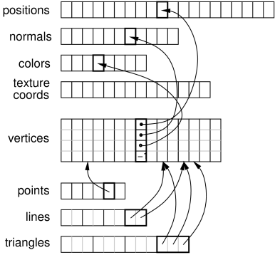
To summarize, primitives are made of vertices, which are in turn comprised of references to attributes (Figure 2.18).
Render objects can be created anywhere within the application program, although care must be taken to synchronize their modification with the render() methods. While an easy way to do this is to create them directly within the render method, care should then be taken to allow them to persist between render invocations, since each time a new object is created, all of its data must be transferred to the GPU. It is recommended to create render objects within prerender(), since this should automatically provide synchronization with both render() and any other thread this is modifying render data. A render object can itself be used to cache rendering data associated with a dynamically varying object, in which case creating (or updating) it from within the prerender method is even more appropriate.
2.4.1 Building a render object
Attributes can be added using a variety of RenderObject methods, including:
Each of these creates an instance of the specified attribute, sets it to the indicated value, adds it to the render object, and assigns it a unique index, which is returned by the add method. The index can be referred to later when adding vertices, or when later changing the attribute’s value (Section 2.4.5). Indices are increased sequentially, starting from zero.
Methods above marked “set by reference” use the supplied array to directly store values within the attribute, so that subsequent changes to the array’s values will also cause the attribute’s values to change.
A vertex is defined by a 4-tuple of indices that can be used to refer
to a previously defined instance of each of the four attributes:
position, normal, color, and texture coordinate. A vertex does not
need to reference all attributes, but it is required that all vertices have a consistent set of attributes (e.g. either all
vertices have a normal reference, or none do). When adding a vertex, a
negative index indicates that the attribute is not present. Since a
vertex can refer to at most one of each attribute, this means that
when building primitives, it may be necessary to define multiple
vertices for the same position if different values are required for
the other attributes (e.g., normals, colors, or texture coordinates).
For example, for the corner of the cube at location ![]() ,
there must be three vertices defined, one each with normals
,
there must be three vertices defined, one each with normals
![]() ,
, ![]() , and
, and ![]() .
.
Referencing attributes by index allows for attributes to be reused, and also for the numbers of any given attribute to vary. For example, when rendering the faces of a solid cube, we typically need 24 vertices (4 for each of the 6 faces), but only 8 positions (one per corner) and 6 normals (one per face).
Vertices can be added using the RenderObject method
where pidx, nidx, cidx, and tidx are the indices of the desired postion, normal, color and texture coordinate attributes (or -1 for attributes that are undefined). The method returns a unique index for the vertex, which can be referred to later when adding primitives. Indices are increased sequentially, starting from zero.
Once vertices are created, they can be used to define and add primitives. Three types of primitives are available: points (one vertex each), lines (two vertices each), and triangles (three vertices each). Methods for adding these include
Each of these takes a set of vertex indices, creates the corresponding primitive, and adds it to the current group for the that primitive (primitive groups are discussed in Section 2.4.7).
Once all the primitives have been added, the Renderer method draw(RenderObject) can then be used to draw all the primitives in the object using the current graphics state. A variety of other draw methods are available for drawing subsets of primitives; these are detailed in Section 2.4.6.
There are no methods to remove individual attributes, vertices, or primitives. However, as described in Section 2.4.5, it is possible to use clearAll() to clear the entire object, after which it may be rebuilt, or clearPrimitives() to clear just the primitive sets.
Listing 3 gives a complete example combining the above operations to create a render object that draws the open tetrahedron described in Section 2.3.2 and Figure 2.7. In this example, the object itself is created using the method createTetRenderObject(). This is in turn called once within prerender() to create the object and store it in the member field myRob, allowing it to then be used as needed within render(). As indicated above, it is generally recommended to create or update render objects within the prerender method, particularly if they need to be modfied to reflect dynamically changing geometry or colors.
2.4.2 “Current” attributes
Keeping track of attribute indices as described in Section 2.4.1 can be tedious. Instead of doing this, one can use the fact that every attribute add method records the index of the added attribute, which then denotes the “current” value for that attribute. The following methods can then be used to add a vertex using various current attribute values:
If any of the attributes have no “current” value, then the corresponding index value is -1 and that attribute will be undefined for the vertex.
If desired, it is possible to set or query the current attribute index, using methods of the form
where <Attribute> is Position, Normal, Color, or TextureCoord and idx is the index of a currently added attribute. For convenience, another set of methods,
will create a new position at the specified location, and then also create a vertex using that position along with the current normal, color and texture coords.
We now give some examples. First, Listing 4 changes the tetrahedron code in Listing 3 to use a current normal in conjuction with vertex(px, py, pz).
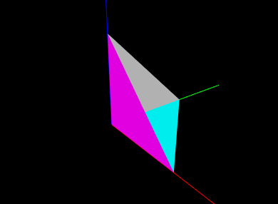
One issue with using vertex(px, py, pz) is that it creates a new position for every vertex, even in situations where vertices can be shared. The example above (implicitly) creates 9 positions where only 4 would be sufficient. Instead, one can create the positions separately (as in Listing 3), and then use vertex(pidx) to add vertices created from predefined positions along with current attribute values. Listing 5 does this for the tetrahedron, while also using a current color to give each face it’s own color. The rendered results are shown in Figure 2.19.
2.4.3 Maintaining consistent attributes
As mentioned earlier, all vertices within a render object must have a consistent set of attributes. That means that if some vertices are defined with normals or colors, they all must be defined with normals or colors, even if it means giving some vertices “dummy” versions of these attributes for primitives that don’t need them.
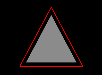
For example, suppose we wish to create an oject that draws a triangular face surrounding by an outer border (Figure 2.20). One might write the following code to create and draw the render object:
This creates a render object containing vertices for the border and triangle, along with the line and triangle primitives. Then render() first draws the border and the triangle, using the renderer’s drawLines() and drawTriangles() methods (described in Section 2.4.6). Because the border is drawn with lighting disabled, no normal is required and so its vertices are created without one. However, as written, this example will crash, because the triangle vertices do contain a normal, and therefore the border vertices must as well. The example can be fixed by moving the addNormal() call in front of the creation of the first three vertices, which will then contain a normal even though it will remain unused.
2.4.4 Adding primitives in “build” mode
The RenderObject can also be systematically constructed using a “build mode”, similar to the draw mode described in Section 2.3.4. Build mode can be invoked for any of the primitive types defined by DrawMode (Table 2.1).
Primitive construction begins with beginBuild(DrawMode) and ends with endBuild(). While in build mode, the application adds vertices using any of the methods described in the previous sections. Then, when endBuild() is called, the render object uses those those vertices to create the primitives that were specified by the mode argument of beginBuild(mode).
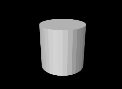
Listing 6 shows a complete example where build mode is used to create a RenderObject for a cylinder. In this example, we first reserve memory for the required attributes, vertices and triangles. This is not a required step, but does help with internal storage. Then, we use a triangle strip to construct the rounded sides of the cylinder, and triangle fans to construct the caps. When constructing the sides, we use vertex(px,py,pz) to create positions and vertices at the same time. Then when constucting the caps, we use addVertex(pidx) to add vertices that reuse the positions created for the sides (knowing that the position indices start at 0). The final cylinder is shown using flat shading in Figure 2.21.
2.4.5 Modifying render objects
Sometimes, an application will build a render object once, and then never change any of its attributes, vertices, or primitives. Such objects are called static, and are the most efficient for rendering purposes since their data only needs to be transmitted to the GPU once. After the renderer first draws the object (using any of the draw methods described in Section 2.4.6), it can continue to draw a static object as many times as needed without having to send more information to the GPU. (Note however that such objects can still be repositioned within the scene by adjusting the model matrix as described in Section 2.2.4). Therefore, applications should attempt to use static render objects whenever possible.
However, often it is necessary to modify a render object. Such modifications may take three forms:
-
•
Vertex changes involving changes to the vertex structure;
-
•
Primitive changes involving changes to the primitive structure;
-
•
Attribute changes involving changes to the attribute structure or the modification of existing attribute values.
Vertex changes occur whenever new vertices are added (using any of the add methods described in the previous sections), or the entire object is cleared using clearAll(). These generally require retransmission of the vertex and attribute information to the GPU.
Primitive changes occur when new points, lines or triangles are added, when all the existing primitives are cleared using clearPrimitives(), or clearAll() is called. Primitive changes generally require retransmission of primitive index data to the GPU.
Attribute changes occur when new attributes are added, existing attribute data is modified, or clearAll() is called. These may require retransmission of the attribute and vertex data to the GPU.
The need to modify existing attribute data often arises when the render object represents some entity that is changing over time, perhaps as the result of a simulation. For instance, if the object represents a deformable surface, the positions and normals associated with that surface will typically be time varying. There are two main ways to modify attribute data. The first is to call one of the render object’s methods for directly setting the attribute’s value,
where idx is the index of the attribute. This will set the attribute’s value within its current group. As with the add attribute methods, those methods marked “set by reference” use the specified array to directly store the values within the attribute, so that later changes to the array’s values will also cause the attribute values to change. (However, if a non-referencing set method is subsequently called, the attribute will allocate its own internal storage, and the reference will be lost.)
This indicates the second way in which attribute data may be modified: if the value was last set using a reference-based add or set method, the attribute can be changed by directly changing the values of that array. However, when this is done, the render object has no way to know that the corresponding attribute data was modfied, and so the application must notify the object directly, using one of the methods
To facilitate the detection of changes, each RenderObject maintains a set of “version” numbers for its attributes, vertices, and primitives, which get incremented whenever changes are made to these quantities. While applications typically do not need to be concerned with this version information, it can be used by renderer implementations to determine what information needs to be retransmitted to the GPU and when. Version numbers can be queried using the following methods:
2.4.6 Drawing RenderObjects
In addition to draw(RenderObject), a variety of other Renderer methods allow the drawing of different subsets of a render objects’s primitives. These include:
Point, line and triangle groups are presented in Section 2.4.7. The method drawPoints(robj,style,rad) draws the indicated points using the specified PointStyle, with rad being either the pixel size or radius, as appropriate. Likewise, drawLines(robj,style,rad) draws the indicated lines using the specified style, with rad being either the line width (in pixels) or the cylinder/spindle/arrow radius.
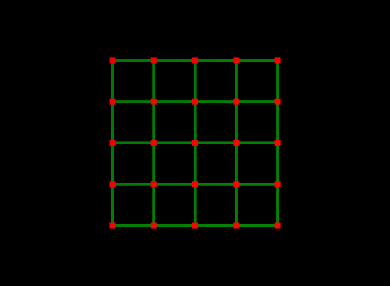
A common reason for drawing different graphics primitives separately is so that they can be drawn with different settings of the graphics state. For example, Listing 7 creates a render object for a simple grid in the x-y plane, and the render method draws the points and lines in different colors. One way to do this would be to assign the appropriate colors to the vertices of all the point and line primitives. Another way, as done in the example, is to simply draw the points and lines separately, with different color settings in the graphics state (this also allows different colors to be used in subsequent renders, without having to modify the graphics object). The result in shown in Figure 2.22.
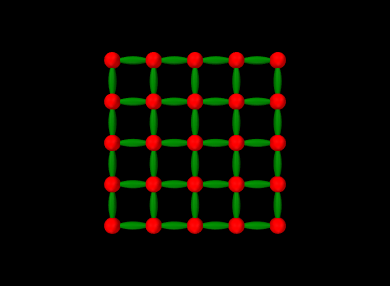
The Renderer methods drawPoints(RenderObject,PointStyle,double) and drawLines(RenderObject,LineStyle,double), described above, can be particularly useful for drawing the points or lines of a render object using different styles. For example, the following code fragment draws the grid of Listing 7 with points drawn as spheres with radius 0.1 and lines drawn as spindles with radius 0.05, with the results shown in Figure 2.23.
2.4.7 Multiple primitive groups
The RenderObject can have multiple groups of a particular primitive type. This is to allow for separate draw calls to render different parts of the object. For example, consider a triangular surface mesh consisting of a million faces that is to be drawn with the left half red, and the right half yellow. One way to accomplish this is to add a vertex color attribute to each vertex. This will end up being quite memory inefficient, since the renderer will need to duplicate the color for every vertex in the vertex buffer. The alternative is to create two distinct triangle groups and draw the mesh with two draw calls, changing the global color between them. New primitive groups can be created using the methods
Each of these creates a new group for the associated primitive type, sets it to be the current group, and returns an index to it.
A group for a particular primitive type is created automatically, if necessary, the first time an instance of that primitive is added to a render object.
Once created, the following methods can be used to set and query the different primitive groups:
Another set of methods can be used to query the primitives within a particular group:
Finally, the draw primitives described in Section 2.4.6 all have companion methods that allow the primitive group to be specified:
To illustrate group usage, we modify the grid example of Listing 7 so that the vertical and horizontal lines are each placed into different line groups:
Once this is done, the horizontal and vertical lines can be drawn with different colors by drawing the different groups separately:
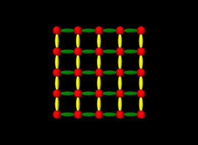
The results are show in Figure 2.24.
As noted in Section 2.4.5, it is possible to clear all primitives using clearPrimitives(). This will clear all primitives and their associated groups within the render object, while leaving vertices and attributes alone, allowing new primitives to then be constructed.
2.4.8 Drawing primitive subsets
In some circumstances, it may be useful to draw only a subset of the primitives in a render object, or to draw a subset of the vertices using a specified primitive type. There may be several reasons why this is necessary. The application may wish to draw different primitive subsets using different settings of the graphics context (such as different colors). Or, an application may use a single render object for drawing a collection of objects that are individually selectable. Then when rendering in selection mode (Section 2.7), it is it is necessary to render the objects separately so that the selection mechanism can distinquish them.
The two renderer methods for rendering primitive subsets are:
Each of these draws primitive subsets for the render object robj, using the vertices specified by idxs and the primitive type specified by mode. VertexIndexArray is a dynamically-sized integer array specialized for vertices. The second method allows a subset of idxs to be specified by an offset and count, so that the same index array can be used to draw different features.
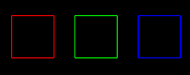
The following example creates a render object containing three squares, and then uses drawVertices() to render each square individually using a different color:
Each square is added to the render object using the method addSquare(), which creates and adds the necessary vertices and line
segments, and also stores the line segment vertex indices in an index
array. The render() method then uses subsets of this index
array, specified by the offset/length pairs ![]() ,
, ![]() , and
, and
![]() , to render each square individually (using a different
color) via a call to drawVertices(). The result is shown in
Figure 2.25.
, to render each square individually (using a different
color) via a call to drawVertices(). The result is shown in
Figure 2.25.
In the above example, each square uses the same number of vertices (8) to draw its line segments, making it easy to determine the offset/length pairs required for each square. However, in more general cases a render object may contain features with variable numbers of vertices, and so determining the offset/length pairs may be more difficult. In such cases the application may find it useful to instead collect the vertex indices inside a FeatureIndexArray, which allows them to be grouped on a per-feature basis, with each feature identified by a number. The usage model looks like this:
After the feature index array has been built, the vertex index buffer can be obtained using fidxs.getVertices(), and the feature number and offset/length pair for each feature can be recovered using
where fidx is the index of the feature within the FeatureIndexArray. In some situations the feature number fnum and fidx may be the same, but in others they may be different. For example, each feature may be associated with an application component that has a unique number used for selection (Section 2.7), in which case the feature number can be set to the selection number.
The three squares example of Listing 8 can be reimplemented using FeatureIndexArray as follows:
![[LOGO]](data:image/png;base64,iVBORw0KGgoAAAANSUhEUgAAAAsAAAAOCAYAAAD5YeaVAAAAAXNSR0IArs4c6QAAAAZiS0dEAP8A/wD/oL2nkwAAAAlwSFlzAAALEwAACxMBAJqcGAAAAAd0SU1FB9wKExQZLWTEaOUAAAAddEVYdENvbW1lbnQAQ3JlYXRlZCB3aXRoIFRoZSBHSU1Q72QlbgAAAdpJREFUKM9tkL+L2nAARz9fPZNCKFapUn8kyI0e4iRHSR1Kb8ng0lJw6FYHFwv2LwhOpcWxTjeUunYqOmqd6hEoRDhtDWdA8ApRYsSUCDHNt5ul13vz4w0vWCgUnnEc975arX6ORqN3VqtVZbfbTQC4uEHANM3jSqXymFI6yWazP2KxWAXAL9zCUa1Wy2tXVxheKA9YNoR8Pt+aTqe4FVVVvz05O6MBhqUIBGk8Hn8HAOVy+T+XLJfLS4ZhTiRJgqIoVBRFIoric47jPnmeB1mW/9rr9ZpSSn3Lsmir1fJZlqWlUonKsvwWwD8ymc/nXwVBeLjf7xEKhdBut9Hr9WgmkyGEkJwsy5eHG5vN5g0AKIoCAEgkEkin0wQAfN9/cXPdheu6P33fBwB4ngcAcByHJpPJl+fn54mD3Gg0NrquXxeLRQAAwzAYj8cwTZPwPH9/sVg8PXweDAauqqr2cDjEer1GJBLBZDJBs9mE4zjwfZ85lAGg2+06hmGgXq+j3+/DsixYlgVN03a9Xu8jgCNCyIegIAgx13Vfd7vdu+FweG8YRkjXdWy329+dTgeSJD3ieZ7RNO0VAXAPwDEAO5VKndi2fWrb9jWl9Esul6PZbDY9Go1OZ7PZ9z/lyuD3OozU2wAAAABJRU5ErkJggg==)