2.3 The Renderer Interface
This section describes the Renderer interface, which supplies the methods which objects can use to draw themselves. This includes methods for setting graphics state, and drawing point, line and triangle primitives as well as simple solid shapes.
2.3.1 Drawing single points and lines
The most basic Renderer methods provide for the drawing of single points, lines, and triangles. The following can be used to draw a pixel-based point at a specified location pnt, or a pixel-based line segment between two points pnt0 and pnt1:
where, as mentioned earlier, Vector3d represents a 3-vector and is defined in maspack.matrix.
Note: while convenient for drawing small numbers of points and lines, the methods described in this section can be quite inefficient. For rendering larger numbers of primitives, one should use either the draw mode methods of Section 2.3.4, or the even more efficient render objects described in Section 2.4.
The size of the points or lines (in pixels) can be controlled via following methods:
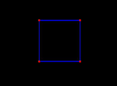
The following example draws a square in the x-z plane, with blue edges and red corners:
In addition to the draw methods described above, we use setShading() to disable and restore lighting (Section 2.3.6), and setColor() to set the point and edge colors (Section 2.3.3). It is generally necessary to disable lighting when drawing pixel-based points and lines which do not (as in this example) contain normal information. The result is shown in Figure 2.6.
For visualization and selection purposes, it is also possible to draw points and lines as solid spheres and cylinders; see the description of this in Section 2.3.1.
2.3.2 Drawing single triangles
Another pair of methods are available for drawing solid triangles:
Each of these draws a single triangle, with a normal computed automatically with respect to the counter-clockwise orientation of the vertices.
Note: as with drawing single points and lines, the single triangle methods are inefficient. For rendering large numbers of triangles, one should use either the draw mode methods of Section 2.3.4, or the render objects described in Section 2.4.
When drawing triangles, the renderer can be asked to draw the front face, back face, or both faces. The methods to control this are:
where FaceStyle is an enumerated type of Renderer with the possible values:
- FRONT:
-
Draw the front face
- BACK:
-
Draw the back face
- FRONT_AND_BACK:
-
Draw both faces
- NONE:
-
Draw neither face
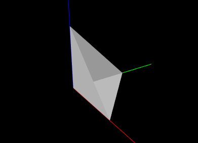
The example below draws a simple open tetrahedron with one face missing:
The result is drawn using the renderer’s default gray color, as seen in Figure 2.7.
2.3.3 Colors and associated attributes
The renderer maintains a set of attributes for controlling the color,
reflectance and emission characteristics of whatever primitives or
shapes are currently being drawn. Color values are stored as RGBA
(red, green, blue, alpha) or RGB (red, green, blue) values in the
range ![]() . The attributes closely follow the OpenGL model for
lighting materials and include:
. The attributes closely follow the OpenGL model for
lighting materials and include:
- Front color:
-
Specifies the reflected RGBA values for diffuse and ambient lighting. The default value is opaque gray:
 .
. - Back color:
-
Optional attribute, which, if not null, specifies the reflected RGBA values for diffuse and ambient lighting for back faces only. Otherwise, the front color is used. The default value is null.
- Specular:
-
Specifies the reflected RGB values for specular lighting. The default value is
 .
. - Emission:
-
Specifies the RGB values for emitted light. The default value is
 .
. - Shininess:
-
Specifies the specular exponent of the lighting equation, in the range
![[0,128]](mi/mi84.png) . The default value is 32.
. The default value is 32.
The resulting appearance of subsequently rendered primitives or shapes depends on the values of these attributes along with the shading settings (Section 2.3.6). When lighting is disabled (by calling setShading(Shading.NONE)), then rendering is done in a uniform color using only the front color (diffuse/ambient) attribute.
The primary methods for setting the color attributes are:
where rgba and rgb are arrays of length 4 or 3 that provide the required RGBA or RGB values. The rgba arguments may also have a length of 3, in which case an alpha value of 1.0 is assumed. For setBackColor(), rgba may also be null, which will cause the back color to be cleared.
Most commonly, there is no difference between the desired front and back colors, in which case one can simply use the various setColor methods instead:
These take RGB or RGBA values and set the front color, while at the same time clearing the back color, so that the front color is automatically applied to back faces. The method setFrontAlpha() independently sets the alpha value for the front color.
To query the color attributes, one may use:
The first four of these return the relevant RGBA or RGB values as an array of floats. Applications may supply the float arrays using the arguments rgba or rgb; otherwise, if these arguments are null, the necessary float arrays will be allocated. If no back color is set, then getBackColor() will return null.
2.3.3.1 Highlighting
The renderer supports the notion of highlighting, which allows the application to indicate to the renderer that subsequently rendered components should be drawn in a highlighted manner. This is typically used to show (visually) that they are selected in some way.
The highlighting style used by the renderer can be queried using the method
At present, only two values of HighlightStyle are supported:
- COLOR:
-
Highlighting is done by rendering with a distinct color.
- NONE:
-
Highlighting is disabled.
The color used for color-based highlighting can be queried using
To enable or disable highlighting, the application can use the methods
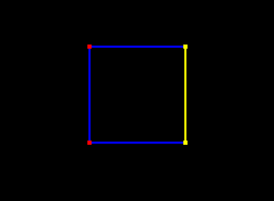
As an illustration, we alter the square drawing example of Section 2.3.1 to highlight the corners corresponding to points p1 and p1, as well as the edge between p1 and p1:
The result, assuming a highlight style of HighlightStyle.COLOR and a yellow highlight color, is shown in Figure 2.8.
2.3.4 Drawing using draw mode
For convenience, the renderer provides a draw mode in which primitive sets consisting of points, lines and triangles can be assembled by specifying a sequence of vertices and (if necessary) normals, colors, and/or texture coordinates between calls to beginDraw(mode) and endDraw(). Because draw mode allows vertex and normal information to be collected together and sent to the GPU all at one time (when endDraw() is called), it can be significantly more efficient than the single point, line and triangle methods described in the previous sections. (However, using render objects can be even more efficient, as described in Section 2.4.)
| DrawMode | Description | Equivalent OpenGL Mode |
|---|---|---|
| POINTS | A set of independent points | GL_POINTS |
| LINES | A set of line segments, with two vertices per segment | GL_LINES |
| LINE_STRIP | A line strip connecting the vertices in order | GL_LINE_STRIP |
| LINE_LOOP | A line loop connecting the vertices in order | GL_LINE_LOOP |
| TRIANGLES | A set of triangles, with three vertices per triangle | GL_TRIANGLES |
| TRIANGLE_STRIP | A triangle strip | GL_TRIANGLE_STRIP |
| TRIANGLE_FAN | A triangle fan | GL_TRIANGLE_FAN |
Draw mode is closely analgous to immediate mode in older OpenGL specifications. The types of primitive sets that may be formed from the vertices are defined by Renderer.DrawMode and summarized in Table 2.1. The primitive type is specified by the mode argument of the beginDraw(mode) call that initiates draw mode.
Between calls to beginDraw(mode) and endDraw(), vertices may be added using the methods
each of which creates and adds a single vertex for the specified point. Normals may be specified using
It is not necessary to specify a normal for each vertex. Instead, the first setNormal call will specify the normal for all vertices defined to that point, and all subsequent vertices until the next setNormal call. If no setNormal call is made while in draw mode, then the vertices will not be associated with any normals, which typically means that the primitives will be rendered as black unless lighting is disabled (Section 2.3.6).
It is also possible to specify per-vertex colors during draw mode. This can be done by calling any of the methods of Section 2.3.3 that cause the front color to be set. The indicated front color will then be assigned to vertices defined up to that point, and all subsequent vertices until the next call that sets the front color. The primitives will then be rendered using vertex coloring, in which the vertex color values are interpolated to determine the color at any given point in a primitive. This color overrides the current front (or back) color value (or mixes with it; see Section 2.3.7). If vertex colors are not specified, then the primitives will be rendered using the color attributes that were in effect when draw mode was first entered.
Finally, per-vertex texture coordinates can be specified within draw mode. The methods for doing this are analagous to those for setting normals,
where Vector2d is defined in maspack.matrix. Texture coordinates are required for any rendering that involves texture mapping, including color, normal or bump maps (Section 2.5).
When draw mode is exited by calling endDraw(), the specified vertices, along with any normal, color or texture information, is sent to the GPU and rendered as the specified primitive set, using the current settings for shading, point size, line width, etc.
As an example, the code below uses draw mode to implement the square drawing of Section 2.3.1 (which is shown in Figure 2.6):
Note that no normals need to be specified since both primitive sets are rendered with lighting disabled.
Another example uses draw mode to implement the partial tetrahedron example from Section 2.3.2 (which is shown in Figure 2.7):
Note that because for this example we are displaying shaded faces, it is necessary to specify a normal for each triangle.
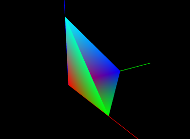
As a final example, we show the tetrahedon example again, but this time with colors specified for each vertex, which initiates vertex coloring. Vertices p0, p1, p2, and p3 are associated with the colors RED, GREEN, BLUE, and CYAN, respectively. The corresponding code looks like this:
and the rendered result is shown in Figure 2.9.
2.3.5 Drawing solid shapes
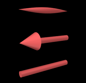
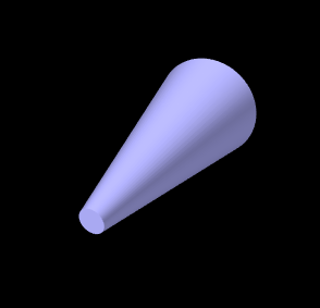
For convenience, the renderer provides a number of methods for drawing solid shapes. These include spheres, cylinders, cubes, boxes, arrows, spindles, cones, and coordinate axes.
Methods for drawing spheres include
both of which draw a sphere with radius rad centered at the point pnt, using the current color and shading settings. For drawing cylinders, arrows, or spindles, one can use
each of which draws the indicated shape between points pnt0 and pnt1 with a cylindrical radius of rad, again using the current color and shading. The argument capped for cylinders and arrows indicates whether or not a solid cap should be drawn over any otherwise open ends. For arrows, the arrow head size is based on the radius and line segment length. Another method,
draws an arrow starting at pnt and extending in the direction dir, with a length given by the length of dir times scale.
A cone can be drawn similarly to a cylinder, using
with the only difference being that there are now two radii, rad0 and rad1, at each end.
 |
 |
 |
To draw cubes and boxes, one may use
The drawCube methods draw an axis-aligned cube with a specified width centered on the point pnt. Similarly, the first two drawBox methods draw an axis-aligned box with the indicated x, y, and z widths. Finally, the last drawBox method draws a box centered on, and aligned with, the coordinate frame defined (with respect to model coordinates) by the RigidTransform3d TBM.
When rendering the curved solids described above, the renderer must create surface meshes that approximate their shapes. The resolution used for doing this can be controlled using a parameter called the surface resolution. This is defined to be the number of line segments that would be used to approximate a circle, and this level of resolution is then employed to create the mesh. The renderer initializes this parameter to a reasonable default value, but applications can query or modify it as needed using the following methods:
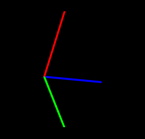
Coordinate axes can be drawn to show the position and orientation of a spatial coordinate frame:
For these, the coordinate frame is described (with respect to the current
model coordinates) by a
RigidTransform3d T. The first method
draws the frame’s axes
as lines with the specified length len and width. The second method allows different lengths (lens) to be
specified for each axis. The axis lines are rendered using regular
pixel-based lines with non-shaded colors, with the ![]() ,
, ![]() , and
, and ![]() axes normally being colored red, green, and blue.
However, if highlight is true and the highlight
style is
HighlightStyle.COLOR
(Section 2.3.3.1), then all axes are drawn
using the using the highlight color.
axes normally being colored red, green, and blue.
However, if highlight is true and the highlight
style is
HighlightStyle.COLOR
(Section 2.3.3.1), then all axes are drawn
using the using the highlight color.
Some of the solids are illustrated in Figure 2.10.
2.3.6 Shading and color mixing
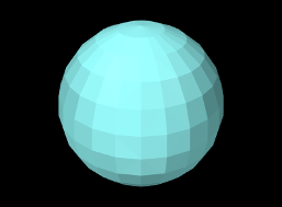
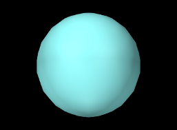
Shading determines the coloring of each rendering primitive (point, line or triangle), as seen from the eye, as a result of its color attributes, surface normals and the current lighting conditions. At any given point on a primitive, the rendered color is the coloring seen from the eye that results from the incident illumination, color attributes, and surface normal at that point. In general, the rendered color varies across the primitive. How this variation is handled depends on the shading, defined by Renderer.Shading:
- FLAT:
-
The rendered color is determined at the first vertex and applied to the entire primitive. This makes it easy to see the individual primitives, which can be desirable under some circumstances. Only one normal needs to be specified per primitive.
- SMOOTH:
-
Rendered colors are computed across the primitive, based on interpolated normal information, resulting in a smooth appearance. The interpolation technique depends on the renderer. OpenGL 2 implementations use Gouraud shading, while the OpenGL 3 renderer uses Phong shading.
- METAL:
-
Rendered colors are computed using a smooth shading technique that may be more appropriate to metalic objects. For some renderer implementations, there may be no difference between METAL and SMOOTH.
- NONE:
-
Lighting is disabled. The rendered color becomes the diffuse color, which is applied uniformly across the primitive. No normals need to be specified.
 |
 |
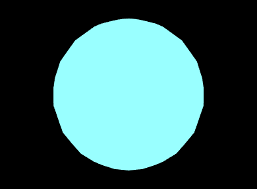 |
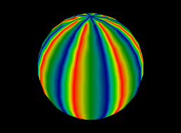
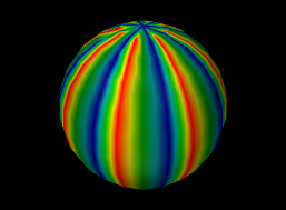
Figure 2.11 shows different shading methods applied to a sphere.
The shading can be controlled and queried using the following methods,
where setShading() returns the previous shading setting.
Lighting is often disabled, using Shading.NONE, when rendering pixel-based points and lines. That’s because normal information is not naturally defined for these primitives, and also because even if normal information were to be provided, shading could make them either invisible or hard to see from certain viewing angles.
2.3.7 Vertex coloring, and color mixing and interpolation
As mentioned in Section 2.3.4, it is possible to specify vertex coloring for a primtive, in which vertex color values are interpolated to determine the color at any given point in the primitive. Vertex colors can be specified by calling setColor primitives while in draw mode. They can also be specified as part of a RenderObject (Section 2.4).
When vertex coloring is used, the interpolated vertex colors either replace or are combined with the current front (or back) diffuse color at each point in the primitive. Other color attributes, such as emission and specular, are unchanged. If lighting is disabled, then the rendered color is simply set to the resulting vertex/diffuse color combination.
Whether the vertex color replaces or combines with the underlying diffuse color is controlled by the enumerated type Renderer.ColorMixing, which has four different values:
| REPLACE | replace the diffuse color (default behavior) |
| MODULATE | multiplicatively combine with the diffuse color |
| DECAL | combine with the diffuse color based on the latter’s alpha value |
| NONE | diffuse color is unchanged (vertex colors are ignored) |
 |
 |
 |
Color mixing can be controlled using these methods:
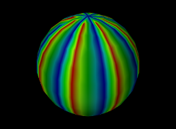
A given Renderer implementation may not support all color mixing modes, and so the hasVertexColorMixing() can be used to query if a given mixing mode is supported. The OpenGL 2 renderer implementation does not support MODULATE or DECAL. Some examples of vertex coloring with different shading and color mixing settings are shown in Figure 2.12.
The renderer’s default color mixing mode is MODULATE. This has the advantage of allowing rendered objects to still appear differently when highlighting is enabled and the highlight style is HighlightStyle.COLOR (Section 2.3.3.1), since the highlight color is combined with the vertex color rather than being replaced by it.
 |
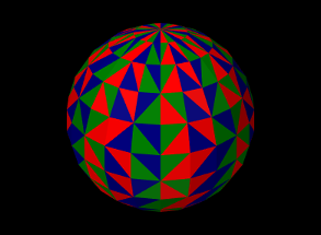 |
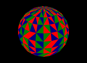
Vertex coloring can be used in different ways. Assigning different colors to the vertices of a primitive will result in a blending of those colors within the primitive (Figures 2.9 and 2.12). Assigning the same colors to the vertices of a primitive can be used to give each primitive a uniform color. Figure 2.13 shows vertex coloring applied to the same sphere as Figures 2.3.6 and 2.12, only with the vertices for each face being uniformly set to red, green or blue, resulting in uniformly colored faces.
 |
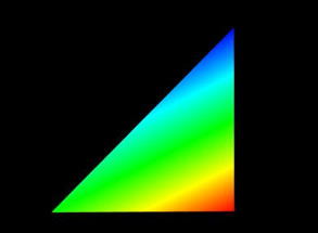 |
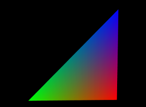
When using vertex coloring, the interpolation of colors across the primitive can be done either in RBG or HSV space. HSV stands for hue, saturation, and value (or brightness), and it is often the best interpolation method to use when the vertex colors have a uniform brightness that the interpolation should preserve. This leads to a “rainbow” look that is common in situations like color-based stress plots. Figure 2.14 illustrates the difference between RGB and HSV interpolation.
Color interpolation is specified with the enumerated type Renderer.ColorInterpolation, which currently has the two values RGB and HSV. Within the renderer, it can be controlled using the methods
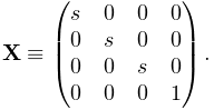
2.3.8 Changing the model matrix
When point positions are specified to the renderer, either as the arguments to various draw methods, or for specifying vertex locations in draw mode, the positions are assumed to be defined with respect to the current model coordinate frame. As described in Section 2.2.4, this is one of the three primary coordinate frames associated with the viewer, with the other two being the world and eye frames.
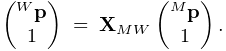
The relationship between model and world frames is controlled by the
model matrix ![]() , which is a
, which is a ![]() homogeneous
affine transform that transforms points in model coordinates (denoted
by
homogeneous
affine transform that transforms points in model coordinates (denoted
by ![]() ) to world coordinates (denoted by
) to world coordinates (denoted by ![]() ), according to
), according to
 |
Initially the world and model frames are coincident, so that ![]() . Rendering methods often redefine the model matrix, allowing
object geometry to be specified in a conveniently defined local
coordinate frame, and, more critically, allowing the predefined
geometry associated with existing rendering objects (Section
2.4) or built-in drawing methods to be used at
different scales and poses throughout the scene. Methods for querying
and controlling the model matrix include:
. Rendering methods often redefine the model matrix, allowing
object geometry to be specified in a conveniently defined local
coordinate frame, and, more critically, allowing the predefined
geometry associated with existing rendering objects (Section
2.4) or built-in drawing methods to be used at
different scales and poses throughout the scene. Methods for querying
and controlling the model matrix include:
Both getModelMatrix() and
getModelMatrix(XMW) return the current model matrix value (where the
value returned by the first method should not be modified).
AffineTransform3dBase is a base class defined
in maspack.matrix and represents a ![]() homogeneous transform
that is either a rigid transform
(of type
RigidTransform3d) or an affine transform
(of type AffineTransform3d).
setModelMatrix(XMW)
explicitly sets the model matrix, while
mulModelMatrix(X)
post-multiplies the current matrix by another rigid or
affine transform
homogeneous transform
that is either a rigid transform
(of type
RigidTransform3d) or an affine transform
(of type AffineTransform3d).
setModelMatrix(XMW)
explicitly sets the model matrix, while
mulModelMatrix(X)
post-multiplies the current matrix by another rigid or
affine transform ![]() , which is equivalent to
setting
, which is equivalent to
setting
translateModelMatrix(tx,ty,tz) and
rotateModelMatrix(zdeg,ydeg,xdeg) translate or rotate the model
frame by post-multiplying the model matrix by a rigid transform
describing either a translation (tx, ty, tz), or
a rotation formed by three successive rotations: zdeg degrees
about the ![]() axis, ydeg degrees about the new
axis, ydeg degrees about the new ![]() axis, and
finally xdeg degrees about the new
axis, and
finally xdeg degrees about the new ![]() axis.
scaleModelMatrix(s)
scales the current model frame by
post multiplying the model matrix by a uniform scaling transform
axis.
scaleModelMatrix(s)
scales the current model frame by
post multiplying the model matrix by a uniform scaling transform
 |
Finally, pushModelMatrix() and popModelMatrix() save and restore the model matrix from an internal stack. It is common to wrap changes to the model matrix inside calls to pushModelMatrix() and popModelMatrix() so that the model matrix is preserved unchanged for subsequent use elsewhere:
2.3.9 Render properties and RenderProps
The maspack.render package defines an object called RenderProps which encapsulates many of the properties that are needed to describe how an oject should be rendered. These properties control the color, size, and style of the three primary rendering primitives: faces, lines, and points, and all are exposed using the maspack.properties package, so that they can be easily set from a GUI or inherited from ancestor components.
A renderable object can maintain its own RenderProps object, and use the associated properties as it wishes to control rendering from within its render() method. Objects maintaining their own RenderProps can declare this by implementing the HasRenderProps interface, which declares the methods
It is not intended for RenderProps to encapsulate all properties relevant to the rendering of objects, but only those which are commonly encountered. Any particular renderable may still need to define and maintain more specialized rendering properties.
Renderable objects that implement both HasRenderProps and IsSelectable (an extension of IsRenderable for selectable objects described in Section 2.7) are identified by the combined interface Renderable.
2.3.9.1 Drawing points and lines as 3D solid objects
RenderProps contains two properties, pointStyle and lineStyle, that indicate whether points and lines should be drawn using standard pixel-based primitives or some type of solid 3D geometry. Often, the latter can be preferable for visualization and graphical selection. pointStyle and lineStyle are described by the enumerated types Renderer.PointStyle and Renderer.LineStyle, respectively, which contain the following entries:
| PointStyle: | |
|---|---|
| POINT | pixel-based point |
| SPHERE | solid sphere |
| CUBE | solid cube |
| LineStyle: | |
| LINE | pixel-based line |
| CYLINDER | solid cylinder |
| SOLID_ARROW | solid arrow |
| SPINDLE | spindle (an ellipsoid tapered at each end) |
The size (in pixels) for pixel-based points is controlled by the property pointSize, whereas the radius for spherical points and half-width for cubic points is controlled by pointRadius. Likewise, the width (in pixels) for pixel-based lines is controlled by lineWidth, whereas the radii for lines rendered as cylinders, arrows or spindles is controlled by lineRadius.
2.3.9.2 RenderProps taxonomy
All of the RenderProps properties are listed in table 2.2. Values for the shading, faceStyle, lineStyle and pointStyle properties are defined using the following enumerated types: Renderer.Shading, Renderer.FaceStyle, Renderer.PointStyle, and Renderer.LineStyle. Colors are specified using java.awt.Color.
| property | purpose | default value |
| visible | whether or not the component is visible | true |
| alpha | transparency for diffuse colors (range 0 to 1) | 1 (opaque) |
| lighting | lighting style: (FLAT, SMOOTH, METAL, NONE) | FLAT |
| shininess | shininess parameter (range 0 to 128) | 32 |
| specular | specular color components | null |
| faceStyle | which polygonal faces are drawn (FRONT, BACK, FRONT_AND_BACK, NONE) | FRONT |
| faceColor | diffuse color for drawing faces | GRAY |
| backColor | diffuse color used for the backs of faces. If null, faceColor is used. | null |
| drawEdges | hint that polygon edges should be drawn explicitly | false |
| colorMap | color map properties (see Section 2.5) | null |
| normalMap | normal map properties (see Section 2.5) | null |
| bumpMap | bump map properties (see Section 2.5) | null |
| edgeColor | diffuse color for edges | null |
| edgeWidth | edge width in pixels | 1 |
| lineStyle: | how lines are drawn (CYLINDER, LINE, or SPINDLE) | LINE |
| lineColor | diffuse color for lines | GRAY |
| lineWidth | width in pixels when LINE style is selected | 1 |
| lineRadius | radius when CYLINDER or SPINDLE style is selected | 1 |
| pointStyle | how points are drawn (SPHERE or POINT) | POINT |
| pointColor | diffuse color for points | GRAY |
| pointSize | point size in pixels when POINT style is selected | 1 |
| pointRadius | sphere radius when SPHERE style is selected | 1 |
In addition to colors for points, lines, and faces, there are also optional colors for edges and back faces. Edge colors (and edge widths) are provided in case an object has both lines and faces, and may want to render the edges of the faces in a color separate from the line color, particularly if drawEdges is set to true. (PolygonalMeshRenderer, described in Section 2.6, responds to drawEdges by drawing the polygonal edges using edgeColor.) Back face colors are provided so that back faces can be rendered using a different color than the front face.
Exactly how a component interprets its render properties is up to the component (and more specifically, up to the render() method for that component). Not all render properties are relevant to all components, particularly if the rendering does not use all of the rendering primitives. For example, some components may use only the point primitives and others may use only the line primitives. For this reason, some components use subclasses of RenderProps, such as PointRenderProps and LineRenderProps, that expose only a subset of the available render properties. All renderable components provide the method createRenderProps() that will create and return a RenderProps object suitable for that component.
2.3.9.3 Renderer methods that use RenderProps
Renderer provides a number of convenience methods for setting attributes and drawing primitives and shapes based on information supplied by RenderProps.
For drawing points and lines, there are
The drawPoint() methods draw a point at location pnt using the pointStyle, pointColor, pointSize, pointRadius and shading properties of props, while the drawLine methods draw a line between pnt0 and pnt1 using the lineStyle, lineColor, lineSize, lineRadius and shading properties. The second drawLine method also allows an alternate color to be specified, as well as whether or not the line shape should be capped (if appropriate). The drawRay() method draws a line starting at pnt and extending along dir, with a length equal to the length of dir times scale. Another method,
is identical to the second drawLine method above except that the line style LineStyle.SOLID_ARROW is assumed. For all methods, the highlight argument can be used to request that the primitive or shape be drawn with highlighting enabled (Section 2.3.3.1).
To draw a line strip, one can use
which draws a line strip with the specified pnts, using the indicated style along with the lineColor, lineSize, lineRadius and shading properties of props. The strip is rendered with highlighting if highlight is true.
There are also methods for setting the color attributes associated with pointColor, lineColor, edgeColor, or faceColor:
These set the renderer’s front color attribute to the value of the indicated color property, use props to also set the shininess and specular attributes, and restore emission to its default renderer value. The first three methods clear the back color attribute, while the setFace methods set it to the backColor value of props. setEdgeColoring() uses lineColor if edgeColor is null, and the second setFace method allows an alternate front color to be supplied as rgba. For all methods, highlighting is enabled or disabled based on the value of highlight. A related method is
which behaves similarly except that the color is explicitly specified using rgba.
Lastly, there are methods to set the shading:
setPointShading() sets the shading to the shading property of props and returns the previous value. setPointShading() does the same, unless pointStyle is PointStyle.POINT, in which case lighting is turned off by setting the shading to Shading.NONE. Similarly, setLineShading() turns off the lighting if lineStyle is LineStyle.LINE.
2.3.10 Screen information and 2D rendering
The screen refers to the 2 dimensional pixelized display on which the viewer ultimately renders the scene. There is a direct linear mapping between the view plane (Figure 2.2.4) and the screen.
While the renderer does not give the application control over the screen dimensions, it does allow them to be queried using
It also allows distances in pixel space to be converted to distances in world space via
distancePerPixel(p) computes the displacement distance of a point p, in a plane parallel to the view plane, that corresponds to a screen displacement of one pixel. centerDistancePerPixel() computes the same thing with p given by the center point (Section 2.2.4).
A renderer may also support 2D mode to facilitate the rendering of 2D objects directly in screen coordinates. 2D mode can be queried with the following methods:
In order for an object to be rendered in 2D, the renderable should
return the flag
IsRenderable.TWO_DIMENSIONAL from its
getRenderHints() method.
The viewer will then call the render() method in two dimensional
mode, with the view matrix set to the identity, and the projection and
model matrices set to provide an orthographic view (Figure
2.4) with the world frame located at the lower left
screen corner, the ![]() axis horizontal and pointing to the right, and
the
axis horizontal and pointing to the right, and
the ![]() axis vertical. The top right corner of the screen corresponds
to the point
axis vertical. The top right corner of the screen corresponds
to the point ![]() , where
, where ![]() and
and ![]() are the width and height of
screen returned by
getScreenWidth() and
getScreenHeight().
Lighting is also disabled and the depth buffer
is turned off, so that rendered objects will always be visible in the
order they are drawn.
are the width and height of
screen returned by
getScreenWidth() and
getScreenHeight().
Lighting is also disabled and the depth buffer
is turned off, so that rendered objects will always be visible in the
order they are drawn.
If a different scaling or origin for the x-y plane is desired, the application can call the renderer method
which will reset the model matrix so that the lower left and upper right of the screen correspond to the points (left, bottom) and (right, top), respectively.
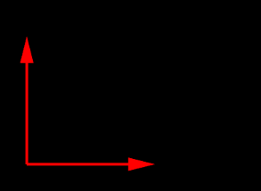
The following example shows the code for a renderable that uses 2D rendering to draw a pair of coordinate axes in the lower left screen corner, with the result shown in Figure 2.15. Its getRenderHints() method returns the TWO_DIMENSIONAL flag to ensure that render() is called in 2D mode. The axis arrowheads are drawn using the method drawArrowHead, which draws an arrowhead in a fixed location and orientation, in combination with changes to the model matrix (Section 2.2.4) to adjust the base location and orientation as required.
2.3.11 Depth offsets
Sometimes, when drawing different primitives that lie on the same plane, the depth buffer cannot properly resolve which primitive should be visible. This artifact is known as “z fighting”. The renderer provides a means to address it via the method
This modifies the projection matrix to incorporate a small offset (in
clip coordinates) along the eye frame’s ![]() axis, so that subsequently
rendered components are rendered slightly closer to (or farther from)
the eye. Each unit of offset equals one unit of depth buffer
precision. The depth offset can be queried using
getDepthOffset(), and the
default value is 0.
axis, so that subsequently
rendered components are rendered slightly closer to (or farther from)
the eye. Each unit of offset equals one unit of depth buffer
precision. The depth offset can be queried using
getDepthOffset(), and the
default value is 0.
 |
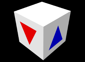 |
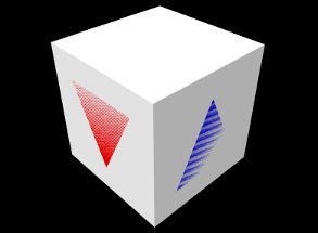
The listing below shows an example in which two colored triangles are drawn on faces of a cube. If no depth offset is set, the triangles compete for visibility with the underlying cube faces (Figure 2.16, left). To resolve this, the render() method sets a depth offset to move the triangles slighting closer to the eye.
z-fighting may still occur if the plane in which the fighting occurs is tilted significantly with respect to the eye. In some situations it may be desirable to mitigate this with a larger offset value.
2.3.12 Maintaining the graphics state
| Attribute | Description | Default value | Restored |
| front color | diffuse/ambient color | (0.5, 0.5, 0.5, 1.0) | no |
| back color | optional color for back faces | null | yes |
| emission | emission color | (0, 0, 0) | yes |
| specular | specular color | (0.1, 0.1, 0.1) | yes |
| shininess | specular color | 32 | yes |
| color interpolation | interpolation method for vertex colors | RGB | yes |
| face style | whether to draw front or back faces | FRONT | yes |
| line width | width of pixel-based lines | 1 | yes |
| point size | size of pixel-based points | 1 | yes |
| model matrix | transform from model to world coordinates | IDENTITY | yes |
| highlighting | highlight drawn primitives | false | yes |
| shading | primitive shading based on normal information | FLAT | yes |
| surface resolution | internal curved surface resolution | 32 | no |
| vertex color mixing | how to combine underlying and vertex colors | REPLACE | yes |
| depth offset | moves rendered objects slightly along the eye z axis | 0 | yes |
| color map | color map properties (Section 2.5) | null | yes |
| normal map | normal map properties (Section 2.5) | null | yes |
| bump map | bump map properties (Section 2.5) | null | yes |
Attributes such as colors, face styles, line widths, matrix values, etc., constitute the graphics state associated with the renderer. Table 2.3 summarizes these attributes and their default values. The last column, Restored, indicates if the renderer will restore the attribute to its default value after calling each renderable’s render() method in the repaint step. All restored attributes can therefore be assumed to be set to their default value at the beginning of any render() method when that method is being called by the renderer.
Note that in some cases, a renderable’s render() method may not be called by the render. This will occur, for instance, when a renderable takes direct control of rendering its subcomponents, and calls their render() methods directly. In such cases, it will be up to either the subcomponents or the parent to maintain the graphics state as required. There are several ways to acccomplish this.
One way is to save and restore each attribute that is modified. To facilitate this, most attribute set methods return the attribute’s previous value. Save and restore can then be done using blocks of the form
As mentioned earlier, the model matrix can be saved and restored using the following:
Alternatively, if it is sufficient to restore an attribute to its default value, one can do that directly:
Finally, the renderer method restoreDefaultState() can be used to restore that default state of all attributes except the front color:
If true, the strictChecking argument causes an exception to be thrown if the renderer is still in a draw mode block (Section 2.3.4) or the model matrix stack is not empty. restoreDefaultState() is used internally by the renderer to restore state.
2.3.13 Text rendering
Some renderer implementations provide the ability to render text objects, using fonts described by the Java class java.awt.Font. Support for text rendering can be querired using the method hasTextRendering(). The methods for drawing text include:
Each of these draws the string str in the x-y plane in model coordinates, using either a specified font or a default. The starting position of the lower left corner of the text box is given by pos, and emSize gives the size of an “em” unit. The methods return the horizontal advance distance of the draw operation.
Other supporting methods for text rendering include:
These set and query the default font, and return the bounds of a text box in a java.awt.geom.Rectangle2D.

The method setupFonts() is called outside the render method to set up some fonts and store them in the member variables myComic and mySerif. Note that setting up fonts in general may be system specific. Three different blocks of text are then drawn within the render() method, with different colors, positions and orientations. The last block consists of multiple lines, with getTextBounds() used to obtain the text bounds necessary to center each line.
Note: Rendered text is shaded in the same way as other surfaces, so unless shading is set to Shading.NONE, light must be shining on it in order for it to be visible. If you want text to always render at full intensity, shading should be set to Shading.NONE.
![[LOGO]](data:image/png;base64,iVBORw0KGgoAAAANSUhEUgAAAAsAAAAOCAYAAAD5YeaVAAAAAXNSR0IArs4c6QAAAAZiS0dEAP8A/wD/oL2nkwAAAAlwSFlzAAALEwAACxMBAJqcGAAAAAd0SU1FB9wKExQZLWTEaOUAAAAddEVYdENvbW1lbnQAQ3JlYXRlZCB3aXRoIFRoZSBHSU1Q72QlbgAAAdpJREFUKM9tkL+L2nAARz9fPZNCKFapUn8kyI0e4iRHSR1Kb8ng0lJw6FYHFwv2LwhOpcWxTjeUunYqOmqd6hEoRDhtDWdA8ApRYsSUCDHNt5ul13vz4w0vWCgUnnEc975arX6ORqN3VqtVZbfbTQC4uEHANM3jSqXymFI6yWazP2KxWAXAL9zCUa1Wy2tXVxheKA9YNoR8Pt+aTqe4FVVVvz05O6MBhqUIBGk8Hn8HAOVy+T+XLJfLS4ZhTiRJgqIoVBRFIoric47jPnmeB1mW/9rr9ZpSSn3Lsmir1fJZlqWlUonKsvwWwD8ymc/nXwVBeLjf7xEKhdBut9Hr9WgmkyGEkJwsy5eHG5vN5g0AKIoCAEgkEkin0wQAfN9/cXPdheu6P33fBwB4ngcAcByHJpPJl+fn54mD3Gg0NrquXxeLRQAAwzAYj8cwTZPwPH9/sVg8PXweDAauqqr2cDjEer1GJBLBZDJBs9mE4zjwfZ85lAGg2+06hmGgXq+j3+/DsixYlgVN03a9Xu8jgCNCyIegIAgx13Vfd7vdu+FweG8YRkjXdWy329+dTgeSJD3ieZ7RNO0VAXAPwDEAO5VKndi2fWrb9jWl9Esul6PZbDY9Go1OZ7PZ9z/lyuD3OozU2wAAAABJRU5ErkJggg==)