6.2 FEM model creation
Creating a finite element model in ArtiSynth typically follows the pattern:
The main code block for the FEM setup should do the following:
-
•
Build the node/element structure
-
•
Set physical properties
-
–
density
-
–
damping
-
–
material
-
–
-
•
Set boundary conditions
-
•
Set render properties
Building the FEM structure can be done with the use of factory methods for simple shapes, by loading external files, or by writing code to manually assemble the nodes and elements.
6.2.1 Factory methods
For simple shapes such as beams and ellipsoids, there are factory methods to automatically build the node and element structure. These methods are found in the FemFactory class. Some common methods are
The inputs specify the dimensions, resolution, and potentially the type of element to use. The following code creates a basic beam made up of hexahedral elements:
6.2.2 Loading external FEM meshes
For more complex geometries, volumetric meshes can be loaded from external files. A list of supported file types is provided in Table 6.3. To load a geometry, an appropriate file reader must be created. Readers capable of reading FEM models implement the interface FemReader, which has the method
Additionally, many FemReader classes have static methods to handle the loading of files for convenience.
| Format | File extensions | Reader | Writer |
|---|---|---|---|
| ANSYS | .node, .elem | AnsysReader | AnsysWriter |
| ANSYS | .cdb | AnsysCdbReader | AnsysCdbWriter |
| TetGen | .node, .ele | TetGenReader | TetGenWriter |
| Abaqus | .inp | AbaqusReader | AbaqusWriter |
| Gmsh | .msh | GmshReader | GmshWriter |
| VTK (ASCII) | .vtk | VtkAsciiReader | – |
The following code snippet demonstrates how to load a model using the AnsysReader.
The method PathFinder.getSourceRelativePath() is used to find a path within the ArtiSynth source tree that is relative to the current model’s source file (Section 2.6). Note the try-catch block. Most of these readers throw an IOException if the read fails, and this must either be caught or thrown by the calling method.
As a different example, the following example creates a GmshReader and uses it to read in a model:
In this case, we create an actual reader instance instead of using one of the static methods, and the IOException is assumed to be handled outside the code fragment. Because the fem argument to readFem() is null, the reader creates a FEM model and returns it. The application must then set other properties for the FEM, such as the material and rendering properties.
One reason to create an actual reader instance is that it may provide access to various options related to the read. For example, both GmshReader and AnsysCdbReader supply the following:
6.2.3 Generating from surfaces
There are two ways an FEM model can be generated from a surface: by using a FEM mesh generator, and by extruding a surface along its normal direction.
ArtiSynth has the ability to interface directly with the TetGen library (http://tetgen.org) to create a tetrahedral volumetric mesh given a closed and manifold surface. The main Java class for calling TetGen directly is TetgenTessellator. The tessellator has several advanced options, allowing for the computation of convex hulls, and for adding points to a volumetric mesh. For simply creating an FEM from a surface, there is a convenience routine within FemFactory that handles both mesh generation and constructing a FemModel3d:
If quality ![]() , then points will be added in an attempt to bound the
maximum radius-edge ratio (see the -q switch for TetGen). According
to the TetGen documentation, the algorithm usually succeeds for a
quality ratio of 1.2.
, then points will be added in an attempt to bound the
maximum radius-edge ratio (see the -q switch for TetGen). According
to the TetGen documentation, the algorithm usually succeeds for a
quality ratio of 1.2.
It’s also possible to create thin layer of elements by extruding a surface along its normal direction.
For example, to create a two-layer slice of elements centered about a surface of a tendon mesh, one might use
For this type of extrusion, triangular faces become wedge elements, and quadrilateral faces become hexahedral elements.
Note: for extrusions, no care is taken to ensure element quality; if the surface has a high curvature relative to the total extrusion thickness, then some elements will be inverted.
6.2.4 Building elements in code
A finite element model’s structure can also be manually constructed in code. FemModel3d has the methods:
For an element to successfully be added, all its nodes must already have been added to the model. Nodes can be constructed from a 3D location, and elements from an array of nodes. A convenience routine is available in FemElement3d that automatically creates the appropriate element type given the number of nodes (Table 6.1):
Be aware of node orderings when supplying nodes. For linear elements, ArtiSynth uses a clockwise convention with respect to the outward normal for the first face, followed by the opposite node(s). To determine the correct ordering for a particular element, check the coordinates returned by the function FemElement3dBase.getNodeCoords(). This returns the concatenated coordinate list for an “ideal” element of the given type.
6.2.5 Example: a simple beam model
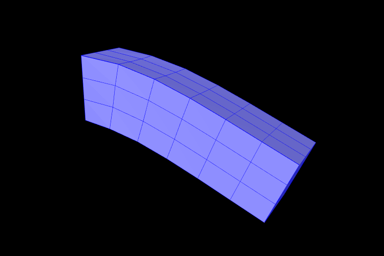
A complete application model that implements a simple FEM beam is given below.
This example can be found in artisynth.demos.tutorial.FemBeam. The build() method first creates a MechModel and FemModel3d. A FEM beam is created using a factory method on line 36. This beam is centered at the origin, so its length extends from -length/2 to length/2. The density, damping and material properties are then assigned.
On lines 45–49, a fixed boundary condition is set to the left-hand side of the beam by setting the corresponding nodes to be non-dynamic. Due to numerical precision, a small EPSILON buffer is required to ensure all left-hand boundary nodes are identified (line 46).
Rendering properties are then assigned to the FEM model on line 52. These will be discussed further in Section 6.12.
![[LOGO]](data:image/png;base64,iVBORw0KGgoAAAANSUhEUgAAAAsAAAAOCAYAAAD5YeaVAAAAAXNSR0IArs4c6QAAAAZiS0dEAP8A/wD/oL2nkwAAAAlwSFlzAAALEwAACxMBAJqcGAAAAAd0SU1FB9wKExQZLWTEaOUAAAAddEVYdENvbW1lbnQAQ3JlYXRlZCB3aXRoIFRoZSBHSU1Q72QlbgAAAdpJREFUKM9tkL+L2nAARz9fPZNCKFapUn8kyI0e4iRHSR1Kb8ng0lJw6FYHFwv2LwhOpcWxTjeUunYqOmqd6hEoRDhtDWdA8ApRYsSUCDHNt5ul13vz4w0vWCgUnnEc975arX6ORqN3VqtVZbfbTQC4uEHANM3jSqXymFI6yWazP2KxWAXAL9zCUa1Wy2tXVxheKA9YNoR8Pt+aTqe4FVVVvz05O6MBhqUIBGk8Hn8HAOVy+T+XLJfLS4ZhTiRJgqIoVBRFIoric47jPnmeB1mW/9rr9ZpSSn3Lsmir1fJZlqWlUonKsvwWwD8ymc/nXwVBeLjf7xEKhdBut9Hr9WgmkyGEkJwsy5eHG5vN5g0AKIoCAEgkEkin0wQAfN9/cXPdheu6P33fBwB4ngcAcByHJpPJl+fn54mD3Gg0NrquXxeLRQAAwzAYj8cwTZPwPH9/sVg8PXweDAauqqr2cDjEer1GJBLBZDJBs9mE4zjwfZ85lAGg2+06hmGgXq+j3+/DsixYlgVN03a9Xu8jgCNCyIegIAgx13Vfd7vdu+FweG8YRkjXdWy329+dTgeSJD3ieZ7RNO0VAXAPwDEAO5VKndi2fWrb9jWl9Esul6PZbDY9Go1OZ7PZ9z/lyuD3OozU2wAAAABJRU5ErkJggg==)