3 The Viewer
The viewer provides interactive graphical rendering of the ArtiSynth model and permits selection of its components. A viewer is integrated into the ArtiSynth main frame; additional viewers can be created if necessary.
3.1 Viewer Toolbar
Each viewer is provided with a toolbar (Figure 7) equipped with icons for controlling the viewpoint (Section 3.2) and clipping planes (Section 3.8). The toolbar for the main viewer appears vertically at the lower left of the main frame, while toolbars for additional viewers appear horizontally at the top. Each is an instance of Java’s JToolBar, and so can be moved and docked accordingly.
3.2 Viewpoint control
The viewpoint can be controlled interactively using mouse drag actions. There are three such actions:
- Rotate
-
Rotates the viewpoint about the viewer center point. By default, this rotation is constrained so the viewer “up” direction remains vertical in the view plane, but this can be changed using the viewer’s rotationMode property (Section 3.10).
- Translate
-
Translates the viewpoint in a plane perpendicular to the line of sight.
- Zoom
-
Zooms in or out by moving the viewpoint along the line of sight.
The mouse button and modifier key combinations required to effect these actions depend on the application’s mouse bindings, which by default are set to either ThreeButton, TwoButton, or OneButton depending on the number of available mouse buttons. Button/key combinations for each of these is described in the following table,
| Action | ThreeButton | TwoButton | OneButton |
|---|---|---|---|
| Rotate | MMB | LMB+ALT | LMB+ALT |
| Translate | MMB+SHIFT | LMB+ALT+SHIFT | LMB+ALT+SHIFT |
| Zoom | MMB+CTRL | LMB+ALT+CTRL | LMB+ALT+CTRL |
where MMB and LMB denote the middle and left mouse buttons. If a mouse wheel is present, then this can also be used to execute zoom actions.
Mouse bindings can also be set explicitly by the user and alternative bindings are available; see Section 3.11.
3.3 Setting aligned axis viewpoints
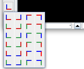
Predetermined viewpoints can also be selected using the align axis button located on the viewer control bar. Clicking on this button produces a popup menu with icons for different axis-aligned views (Figure 8). Each view is indicated by the two axes perpendicular to the line of sight, with the X, Y, and Z axes illustrated by red, green, and blue lines respectively. Some examples are:
| Z axis up, X axis to the right. | |
| Z axis up, X axis to the left. | |
| Y axis up, X axis to the right. | |
| Y axis down, X axis to the right. | |
| Z axis up, y axis to the right. | |
| Z axis up, y axis to the left. |
The align axis button itself displays the most recently selected axis-aligned view, and the popup menu shows this view in the upper left corner. Reselecting the current view will simply realign the viewer’s viewpoint to the current view; hitting the ‘v’ key from within the viewer (Section 3.12) will do the same.
3.4 Adding additional viewers
Additional viewers can be created by selecting View > New viewer from the main menu. Each viewer provides independent viewing and selection control for the current model.
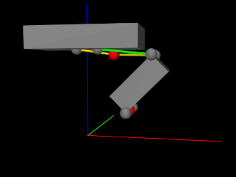
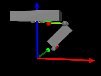
3.5 World coordinate axes
Hitting the ’a’ key from within the viewer enables or
disables drawing of the world coordinate axes. By default, these are
drawn as simple lines, with the ![]() ,
, ![]() and
and ![]() axes colored red,
green and blue, respectively, and the axis length computed
automatically based on the model size.
axes colored red,
green and blue, respectively, and the axis length computed
automatically based on the model size.
 |
 |
3.6 Orthographic vs. perspective projection
The user can toggle between orthographic and perspective projection by selecting View > Orthographic view or View > Perspective view from the main menu. Toggling can also be achieved using the ‘o’ key shortcut (Section 3.12) within the viewer.
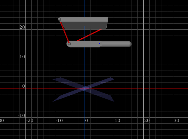
3.7 Viewer grid
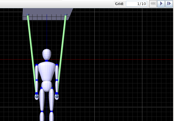
Hitting the ‘g’ key within the viewer enables or disables a grid (Figure 10). Grid cells are square and appear in two resolutions, with major cells subdivided into a number of minor cells. Major cells are typically rendered more brightly than minor cells. By default, the grid computes the cell sizes automatically based on the current viewer zoom-level. However, it is possible to set an explicit grid resolution (see 3.7.1).
The grid is located in the plane perpendicular to the line of sight of the most recently selected axis-aligned view. To change the grid plane, select a new axis aligned viewpoint (Section 3.3).
3.7.1 Grid units
When the grid is enabled, a box labeled Grid: appears in the toolbar on top of the main ArtiSynth frame which gives the current resolution of the grid, displayed as S/N, where S is the size of each major grid cell and N is the number of subdivisions per cell. If there are no subdivisions, then the /N is omitted. For example, in Figure 10, this appears as Grid: 1/10, which means that the major grid cells have a size of 1.0 and are each divided into 10 subdivisions. The numeric value of the ratio S/N gives the minor cell size.
By default, the grid automatically resizes itself to the current viewer zoom level, choosing well-rounded numbers for the grid cell size. Auto-sizing can be enabled or disabled by right-clicking on the Grid: label and choosing Turn auto-sizing on or Turn auto-sizing off, as appropriate. The user can also specify an explicit value for the grid resolution by entering the desired S/N value (or just an S value) into the Grid: box. Specifying an explicit value will disable auto-sizing, unless S is specified as 0 or the special value * is entered, both of which will re-enable auto-sizing.
3.7.2 Axis labeling
Hitting the ‘l’ key within the viewer enables or disables labeling of the major divisions along the horizontal and vertical axis (Figure 11). The division lines along which these labels appear are automatically adjusted so as to ensure proper label visibility, and do not necessarily correspond to the x, y, or z axes.
It is possible to control various properties associated with axis labeling, such as which axes are labeled, and the label size and color. See the next section on Grid properties.
3.7.3 Grid properties
The grid has a number of properties that can be set by right-clicking in the viewer and choosing Set viewer grid properties (or by right-clicking on the Grid: label and choosing Set properties). This will bring up a property dialog, such as that shown in Figure 12.
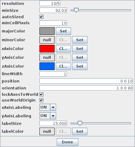
Properties that can be set include:
- resolution
-
Grid resolution, as described above.
- autoSized
-
If true, causes the grid resolution to be recomputed as the user adjusts the view position, orientation, and zoom.
- minCellPixels
-
Minimum number of pixels that should appear in a minor cell division when autosizing.
- majorColor
-
Color to use for the major axis lines.
- minorColor
-
Color to use for the minor axis lines.
- xAxisColor
-
Color to use for the grid line that corresponds to the world y axis, or the horizontal axis if lockAxesToWorld is false.
- yAxisColor
-
Color to use for the grid line that corresponds to the world y axis, or the vertical axis if lockAxesToWorld is false.
- zAxisColor
-
Color to use for the grid line that corresponds to the world z axis.
- lineWidth
-
Width of the grid lines, in pixels.
- position
-
Translation position of the grid, in world coordinates.
- orientation
-
Orientation of the grid, in world coordinates.
- lockAxesToWorld
-
If true, forces the grid to stay aligned with the orientation and position of the world axes. In particular, the horizontal and vertical axes will always be parallel to one of the x, y, or z world axes, the grid center will be a multiple of major cell sizes from the origin, and axis labels will be set relative to the world origin.
- useWorldOrigin
-
If true, causes the principal horizontal and vertical axes to be aligned with the world origin. Otherwise, the axes will be aligned with the grid center. This property can only be true if lockAxesToWorld is also true.
- xAxisLabeling
-
Enables labeling of the x axis.
- yAxisLabeling
-
Enables labeling of the y axis.
- labelSize
-
’em’ size of the label text, in pixels.
- labelColor
-
If set, specifies the color used to draw the label text. Otherwise, the major axis color is used.
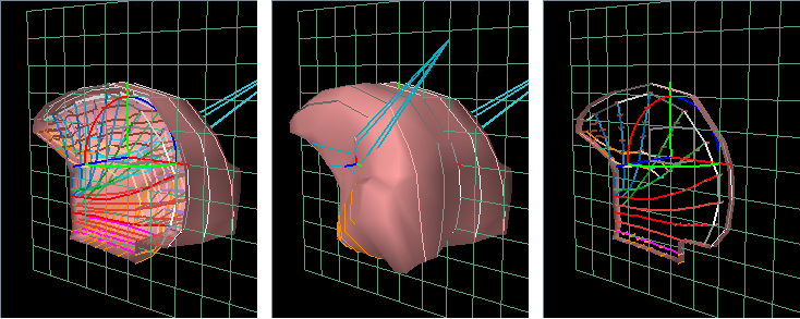
3.8 Clipping planes
The user can add clipping planes to the viewer. These are useful for restricting what is rendered and allowing a better view of interior structures, as shown in (Figure 13).
3.8.1 Adding and removing
To add a clipping plane, left click on the add clip plane
button ![]() located on the
viewer toolbar. This will create a clipping plane located in the plane
perpendicular to the current line of sight.
located on the
viewer toolbar. This will create a clipping plane located in the plane
perpendicular to the current line of sight.
It will also add to the viewer toolbar a clip plane icon
![]() for controlling the
clipping plane. Right-clicking on this icon will bring up an option
menu.
for controlling the
clipping plane. Right-clicking on this icon will bring up an option
menu.
To delete a clipping plane, right-click on its icon and select Delete.
3.8.2 Moving
A clip plane is associated with a coordinate system and can be moved and/or rotated by dragging on the trans-rotate transformer located at its coordinate system origin. The clip region is the half space lying in the direction of the +z axis.
The transformer itself can be made invisible/visible by right-clicking on the clip plane icon and selecting Hide transformer or Show transformer.
3.8.3 Offsets
The clipping region is the half space lying in the direction of the +z axis of the plane’s local coordinate system. By default, clipping is actually offset by a small distance along the +z axis, so that small objects (such as points) lying in the x-y plane remain visible. The amount of this offset is controlled by the plane’s offset property, which is set to a nominal default value. To control this property directly, right-click on the clip plane icon and select Set properties. This will bring up a panel which allows the offset to be adjusted.
3.8.4 Enabling/disabling
Left clicking on the clip plane icon will enable/disable
clipping. Disabling clipping allows the plane to be used as a regular
movable grid. When clipping is disabled, the icon
will change to the form
![]() .
.
3.8.5 Slicing mode
Clipping planes can be placed in a slicing mode, whereby half-spaces in both the positive and negative z directions are clipped. The result is a small slice about the local x-y plane (Figure 13, right). The width of this slice is controlled by the plane’s offset property, as described above.
To enable or disable slicing, right-click on the clip plane icon and select Enable slicing or Disable slicing.
3.8.6 Other features
- Properties
-
Various properties associated with the plane, such as its color, line width, cell resolution, etc., can be set explicitly by the user. To do this, right-click on the icon, select Set properties, and edit the resulting property panel. Most properties are the same as those described for the main viewer grid in 3.7.3.
- Grid visibility
-
To make the grid invisible/visible, right-click on the icon and select Hide grid or Show grid.
- Alignment with world axes
-
The clip plane can be aligned so that it’s normal lies along the positive or negative direction of either the x, y, or z world axes. Right-click on the icon and select the appropriate option. Clipping is performed so that the half-space lying in the direction of the normal is clipped.
- Alignment with current line of sight
-
To align the clipping plane so that it is perpendicular to the current line of sight, right-click on the icon and select Reset.
3.9 Indicating 3D positions with the mouse
It is possible to use a viewer in combination with a mouse to specify the position of a 3D point in space. This is commonly employed in the editing operations described in Section 16.
To specify a point, the user left-clicks the mouse in the viewer, at the screen position located over the point’s desired position. The 3D position is then determined by intersecting the ray indicated by the mouse clock with some appropriate surface or plane. Typically, a plane perpendicular to the viewing direction and passing through the model’s center is used. Alternatively, some interactions provide a constrain to plane option, which causes the ray to be intersected with a viewer clipping plane (Section 3.8), providing more precise control over the point’s position. This requires that the viewer presently contain at least one clipping plane. If more than one clipping plane is present, the first one is used.
In other applications, the desired point may be known to lie on a 3D surface, in which case the position is determined by intersecting the ray with a 3D surface mesh.
3.10 Viewer properties
Viewers export a number of properties that control various aspects of their look and feel. Some of these can be modified collectively for all viewers by choosing “Settings > Viewers ...” from the main menu, which opens a viewer settings dialog (Figure 14).
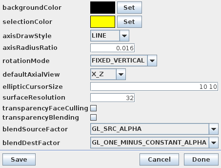
Various properties can be set by this dialog, as described below. Clicking the Save button will save the current settings to the user’s preferences (Section 11.2) so that they will be set automatically when ArtiSynth is restarted.
Properties set by the viewer settings dialog include:
- backgroundColor
-
Color of the viewer background.
- selectionColor
-
Color used to highlight selected items.
- axisDrawStyle
-
Controls how world coordinate axes are drawn (Section 3.5), with LINE and ARROW specifying simple lines and solid arrows, respectively.
- axisRadiusRatio
-
A ratio which can be used to determine the radius for an axis when the radius is not explicitly specified. The radius is computed by multiplying the ratio by the axis length. This is typically used when rendering coordinate axes as solid arrows and has a default value of 0.016.
- rotationMode
-
Controls how the eye-to-world rotation is adjusted when the mouse is used to perform a rotate action (Section 3.2). The default value is FIXED_VERTICAL, which constrains the viewer’s “up” vector to remain vertical with respect to the view plane, at the expense of preventing the eye-to-world rotation from being adjustable to an arbitrary value. Alternate values include CONTINUOUS, which enables a track-ball type rotation that does allow arbitrary adjustment of the eye-to-world rotation, and OFF, which disables rotation adjustment.
- defaultAxialView
-
Sets the default axis alignment indicating how the 3D world axes correspond to the horizontal “right” and vertical “up” view plane directions. Each setting takes the form
 _
_ , where is the
world axis pointing right and is the axis pointing up, and and
can each be either X, Y, Z, NX, NY,
or NZ, indicating the positive or negative
, where is the
world axis pointing right and is the axis pointing up, and and
can each be either X, Y, Z, NX, NY,
or NZ, indicating the positive or negative  ,
,  or
or  axis.
axis. - ellipticCursorSize
-
Size of the elliptic cursor (Section 4.3.2) in the horizontal and vertical directions. The default value is
 .
. - surfaceResolution
-
Controls the number of faces or segments used for rendering built-in curved primitives, such as cylinders and spheres. For cylinders, it controls the number of sides, while for spheres it controls the number of longitudinal slices. A larger number produces a smoother effect at increased graphical cost. The default value is 32.
For OpenGL based viewers, the following properties are also provided to control how transparency is rendered:
- transparencyFaceCulling
-
Enables or disables face culling when rendering transparency.
- transparencyBlending
-
Enables or disables transparency blending (via glEnable() or glDisable() using GL_BLEND) when rendering transparency.
- blendSourceFactor
-
Specifies the first (source) argument to glBlendFunc().
- blendDestFactor
-
Specifies the second (destination) argument to glBlendFunc().
3.10.1 Viewer-specific properties
Viewer properties can also be set on a per-viewer basis. To do this, invoke the context menu (usually right-click) in the viewer when nothing is selected, and choose Set viewer properties. Individual properties include all those described above (except with defaultAxialView renamed to axialView), together with the following additional properties:
- axisLength
-
Axis lengths used to render the world axes (Section 3.5).
- viewControlMask
-
If set to ALONG_X_ONLY or ALONG_Y_ONLY, mouse-based view control inputs are restricted to those in the x or y screen directions, respectively. This makes it easier to limit changes in the view point. The default value is NONE (no restriction).
- eye
-
Location of the eye position, in world coordinates.
- center
-
Location of the viewing frustum center, in world coordinates.
Setting a viewer-specific property, such as the background color, will generally cause it to have a value that differs from its counterpart in the viewer settings (because the value was set for only a single viewer). On the other hand, properties set in the viewer settings will be applied to all open viewers.
3.11 Mouse Bindings
The ArtiSynth GUI was originally designed for a three-button mouse, in which the left button is used for selection, the middle button controls the viewpoint, and the right button is used to activate the context menu. These are used in conjunction with the modifier keys SHIFT and CTRL to effect different actions.
For systems that do not have a three-button mouse, ArtiSynth by default detects the number of mouse buttons and adjusts the mouse bindings so that the ALT key emulates the middle button and the META key emulates the right button.
The META key is usually associated with either the COMMAND key (Mac) or the WINDOWS key.
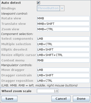
Mouse bindings can also be explicitly set by the user, by choosing “Settings > Mouse ...” from the main menu, which opens a mouse bindings dialog (Figure 15). This allows the user to change the bindings, and also for any given binding describes the button/key combinations to effect various actions. If the “Auto detect” checkbox is selected, then the bindings are determined automatically from the number of available mouse buttons. Unchecking this box allows the bindings to be set explicitly using the Bindings selector. The dialog also allows control of the scale factor used for mouse wheel zoom actions.
Clicking the Save button in the mouse bindings dialog will save the current bindings to the user’s preferences (Section 11.2) so that they will be set automatically when ArtiSynth is restarted. Mouse bindings can also be specified explicitly at startup using the -mousePrefs <bindings> command line option.
Currently, there are five bindings available:
- ThreeButton
-
Default bindings for a three-button mouse.
- TwoButton
-
Default bindings for a two-button mouse. The middle mouse button is emulated with the ALT key.
- OneButton
-
Default bindings for a one-button mouse. The middle and right mouse buttons is emulated with the ALT and META keys.
- Laptop
-
Legacy bindings for a two-button mouse.
- Mac
-
Legacy bindings for a Mac type one-button mouse.
Tables showing the button and modifier key combinations that effect different actions for each of these are given below, with LMB, MMB, and RMB denoting the left, right and middle mouse buttons. Actions marked with an asterisk (*) are drag actions which can have their modifier keys invoked or removed during a drag operation. Button/key combinations for ThreeButton, TwoButton, and OneButton are:
| Action | ThreeButton | TwoButton | OneButton |
|---|---|---|---|
| Viewpoint control (Section 3.2) | |||
| Rotate view | MMB | LMB+ALT | LMB+ALT |
| Translate view | MMB+SHIFT | LMB+ALT+SHIFT | LMB+ALT+SHIFT |
| Zoom view | MMB+CTRL | LMB+ALT+CTRL | LMB+ALT+CTRL |
| Component selection (Section 4.3) | |||
| Select components | LMB | LMB | LMB |
| Multiple selection | LMB+CTRL | LMB+CTRL | LMB+CTRL |
| Elliptic selection | LMB | LMB | LMB |
| Elliptic deselection |
LMB+SHIFT | LMB+SHIFT | LMB+SHIFT |
| Resize elliptic cursor | LMB+SHIFT+CTRL | LMB+SHIFT+CTRL | LMB+SHIFT+CTRL |
| Context menu | RMB | RMB | LMB+META |
| Manipulator controls (Section 5.2) | |||
| Move dragger | LMB | LMB | LMB |
| Dragger constrain |
LMB+SHIFT | LMB+SHIFT | LMB+SHIFT |
| Dragger reposition |
LMB+CTRL | LMB+CTRL | LMB+CTRL |
while those for Laptop and Mac are:
| Action | Laptop | Mac |
| Viewpoint control (Section 3.2) | ||
| Rotate view | LMB | LMB+ALT |
| Translate view | LMB+SHIFT | LMB+ALT+SHIFT |
| Zoom view | LMB+ALT | LMB+ALT+META |
| Component selection (Section 4.3) | ||
| Select components | LMB+CTRL | LMB |
| Multiple selection | LMB+SHIFT+CTRL | LMB+META |
| Elliptic selection | LMB+CTRL | LMB |
| Elliptic deselection |
LMB+SHIFT+CTRL | LMB+SHIFT |
| Resize elliptic cursor | LMB+SHIFT+CTRL | LMB+SHIFT+CTRL |
| Context menu | RMB | LMB+CTRL |
| Transformer control (Section 5.2) | ||
| Move dragger | LMB | LMB |
| Dragger constrain |
LMB+SHIFT | LMB+SHIFT |
| Dragger reposition |
LMB+ALT | LMB+ALT |
3.12 Keyboard shortcuts
When the viewer has the keyboard focus, the following key shortcuts are available:
| Key | Operation |
|---|---|
| q | quit ArtiSynth |
| t | toggle time line visibility |
| z | undo last command |
| Play controls (Section 2.6): | |
| p or SPC | play/pause |
| s | single step |
| r | reset |
| Viewer controls: | |
| v | reset view (Section 3.2) |
| o | toggle orthographic/perspective view (Section 3.6) |
| a | toggle visibility of axes showing world coordinates |
| g | toggle viewer grid (Section 3.7) |
| l | toggle viewer grid labels |
| Selection and transformer (Sections 4.3 and 5.2): | |
| ESC | select parent of last selection |
| c | clear selection |
| d | reset elliptic cursor size to default |
| w | set current transformer frame to world coordinates |
| b | set current transformer frame to body/local coordinates |
![[LOGO]](data:image/png;base64,iVBORw0KGgoAAAANSUhEUgAAAAsAAAAOCAYAAAD5YeaVAAAAAXNSR0IArs4c6QAAAAZiS0dEAP8A/wD/oL2nkwAAAAlwSFlzAAALEwAACxMBAJqcGAAAAAd0SU1FB9wKExQZLWTEaOUAAAAddEVYdENvbW1lbnQAQ3JlYXRlZCB3aXRoIFRoZSBHSU1Q72QlbgAAAdpJREFUKM9tkL+L2nAARz9fPZNCKFapUn8kyI0e4iRHSR1Kb8ng0lJw6FYHFwv2LwhOpcWxTjeUunYqOmqd6hEoRDhtDWdA8ApRYsSUCDHNt5ul13vz4w0vWCgUnnEc975arX6ORqN3VqtVZbfbTQC4uEHANM3jSqXymFI6yWazP2KxWAXAL9zCUa1Wy2tXVxheKA9YNoR8Pt+aTqe4FVVVvz05O6MBhqUIBGk8Hn8HAOVy+T+XLJfLS4ZhTiRJgqIoVBRFIoric47jPnmeB1mW/9rr9ZpSSn3Lsmir1fJZlqWlUonKsvwWwD8ymc/nXwVBeLjf7xEKhdBut9Hr9WgmkyGEkJwsy5eHG5vN5g0AKIoCAEgkEkin0wQAfN9/cXPdheu6P33fBwB4ngcAcByHJpPJl+fn54mD3Gg0NrquXxeLRQAAwzAYj8cwTZPwPH9/sVg8PXweDAauqqr2cDjEer1GJBLBZDJBs9mE4zjwfZ85lAGg2+06hmGgXq+j3+/DsixYlgVN03a9Xu8jgCNCyIegIAgx13Vfd7vdu+FweG8YRkjXdWy329+dTgeSJD3ieZ7RNO0VAXAPwDEAO5VKndi2fWrb9jWl9Esul6PZbDY9Go1OZ7PZ9z/lyuD3OozU2wAAAABJRU5ErkJggg==)