9 Adding and Editing Numeric Probes
Numeric input and output probes can be interactively added to a simulation. Output probes allow you to record a vector of values derived from one or more model component properties. Input probes allow you to use a vector of input data to drive one or more model component properties.
9.1 Adding output probes
To add a numeric output probe, go to the main menu and choose edit > add output probe. This will create a numeric output probe editor, as shown in Figure 46.
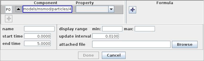
The editor contains three main panels:
-
•
A property panel at the upper left in which allows you to add or edit the properties of model components whose values will be used in computing the final output probe value. Each property is associated with a component/property widget, which allows you to first select a component and then choose one of its properties.
-
•
A formula panel at the the upper right which allows you to add or edit formulae which convert the values from the properties into numeric values for the output probe.
-
•
A probe property panel at the bottom which allows properties of the probe itself to be set.
9.1.1 Creating a simple probe
Creating an output probe that simply records the value of a single numeric property is fairly easy. Starting with the output probe editor in Figure 46:
-
1.
Select a component, either externally through the navigation panel (Section 4.2), the viewer (Section 4.3), or the selection display (Section 4.4), or by entering its path name into the component/property widget. Once a component is selected, the left-most “up” arrow can be used to select that component’s parent.
-
2.
Select a property for the component from the property selection box at the right of the component/property widget.
-
3.
Adjust any required properties for the probe itself (Section 9.3).
-
4.
Click Done.
9.1.2 General output probes
The incorporation of Jython formulae into output probes as described in this section can be difficult to implement in code. Instead, users are encouraged to use NumericMonitorProbes to create output probe data based on general functions. See the section “Numeric monitor probes” in the ArtiSynth Modeling Guide.
In general, output probes define a general map from the numeric values of n model component properties to a generalized output vector formed by the concatenation of m-subvectors formed by m formulae, as shown in Figure 47. In the simple case of Section 9.1.1, there is a single property, one sub-vector equal to the output vector, and a formula which is just the property value itself.
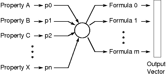
Each of the n properties has a numeric value which is
represented by a variable ![]() and which is a vector of some dimension
(scalars being considered vectors of dimension 1). The dimension of
the
and which is a vector of some dimension
(scalars being considered vectors of dimension 1). The dimension of
the ![]() depends on the property and is displayed to the right of the
property selection box on the component/property widget.
depends on the property and is displayed to the right of the
property selection box on the component/property widget.
Each of the m formulae is an arithmetic expression, implemented in
Jython (Section 12), which may involve one or
more of the variables ![]() . The output from each formula is itself a
vector of dimension
. The output from each formula is itself a
vector of dimension ![]() , which is displayed at the right of each
formula panel. The simplest formula is just a single variable
, which is displayed at the right of each
formula panel. The simplest formula is just a single variable ![]() ,
in which case
,
in which case ![]() equals the dimension of
equals the dimension of ![]() . The concatenation
of all the output vectors from all the formulae produces the output
vector associated with the probe, which has a dimension
. The concatenation
of all the output vectors from all the formulae produces the output
vector associated with the probe, which has a dimension ![]() .
.
9.1.3 Using the probe editor
What the probe editor allows you to do is create the above mentioned map by selecting the properties of model components, assigning variable names to them, and creating formulae using these variables. When all the selected components form a coherent mapping, the Done button will be enabled and the probe can be completed. When one or more parts of the mapping is unspecified or incomplete, the associated widgets will be highlighted and the Done button will be disabled.
Extra properties can be added by requesting additional component/property widgets using the "+" button in the property panel. Similarly, extra formulae can be requested using the add button in the formula panel.
Properties and formulas can also be deleted; simply right click on the associated widget and choose delete.
Property variable names appear in a box at the left of the component/property widget. Variable names can be changed by editing this box. Name changes will be propagated into the formulae.
In order to streamline the probe creation process, the editor will try to guess certain desired actions. In particular, when the user chooses a property with a given component/property widget for the first time, the editor assigns a variable name to that property and creates a formula panel containing that variable. The variable name and formula panel can be changed if necessary.
Note:
The selection manager is connected to at most one component/property widget at a time. The component field for this widget is indicated with a blue border; external selections will affect only that widget. Left clicking on a component/property widget will cause it to be connected to the selection manager.
9.2 Adding input probes
To add a numeric input probe, go to the main menu and choose edit > add input probe. This will create a numeric input probe editor, as shown in Figure 48.
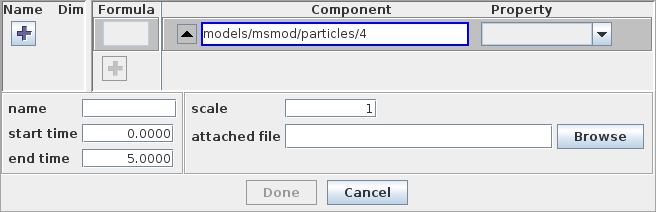
The editor contains three main panels:
-
•
An input panel at the upper left which allows you to add or edit input variables. Each of these variables represents a sub-vector of the probe’s numeric input vector.
-
•
A formula/property panel at the the upper right which allows you to add or edit numeric properties (using component/property widgets), along with formulae to determine values for these properties based on the input variables.
-
•
A probe property panel at the bottom which allows properties of the probe itself to be set.
9.2.1 Creating a simple probe
Creating an input probe that simply sets a single numeric property from the probe’s input vector is fairly easy, and is exactly analogous to creating a simple output probe (Section 9.1.1). Starting with the input probe editor in Figure 48:
-
1.
Select a component, either externally, or using the component/property widget.
-
2.
Select a property for the component from the property selection box at the right of the component/property widget.
-
3.
Adjust any required properties for the probe itself (Section 9.3).
-
4.
Click Done.
9.2.2 General input probes
The incorporation of Jython formulae into input probes as described in this section can be difficult to implement in code. Instead, users are encouraged to use NumericControlProbes to create general control inputs based on input probe data. See the section “Numeric input probes” in the ArtiSynth Modeling Guide.
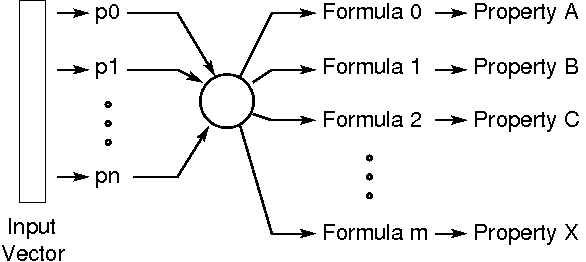
In general, input probes define a general map from the probe’s
input vector (which is subdivided into n input variables
of dimension ![]() ) to the values of m properties, where each
value is determined by an independent formula based
on the input variables (Figure 49).
In the simple case of Section 9.2.1,
there is one input variable which equals the input vector,
and it drives a single property using a formula which is
just the value of the input vector.
) to the values of m properties, where each
value is determined by an independent formula based
on the input variables (Figure 49).
In the simple case of Section 9.2.1,
there is one input variable which equals the input vector,
and it drives a single property using a formula which is
just the value of the input vector.
Each input variable is a vector of dimension ![]() (scalars being
considered vectors of dimension 1), and the sum of all the
(scalars being
considered vectors of dimension 1), and the sum of all the ![]() equals
the dimension of the input vector.
equals
the dimension of the input vector.
Each of the formulae controlling the properties is an arithmetic
expression, implemented in Jython (Section 12),
which may involve one or more of the input variables ![]() . The output
from each formula is itself a vector whose dimension must match the
associated numeric property. The simplest formula is just a single
variable
. The output
from each formula is itself a vector whose dimension must match the
associated numeric property. The simplest formula is just a single
variable ![]() , in which case its dimension equals the dimension of
, in which case its dimension equals the dimension of
![]() .
.
9.2.3 Using the probe editor
The probe editor allows you to create the above mentioned map by creating input variables, selecting properties, and creating formulae to drive these properties. When all the selected components form a coherent mapping, the Done button will be enabled and the probe can be completed. When one or more parts of the mapping is unspecified or incomplete, the associated widgets will be highlighted and the Done button will be disabled.
Extra properties can be added by requesting additional component/property widgets using the "+" button in the formula/property panel. Similarly, extra input variables can be requested using the add button in the formula panel.
Properties and input variables can also be deleted; simply right click on the associated widget and choose delete.
Each input variable is associated with a widget containing two text fields, the left one defining the variable’s name and the right one its dimension. The name or dimension can be changed by editing these fields. Changes will be propagated into the formulae; formulae that are found to be incompatible with the changes will be cleared.
In order to streamline the probe creation process, the editor will try to guess certain desired actions. In particular, when the user chooses a property with a given component/property widget for the first time, the editor creates an input variable whose dimension matches the property, and a simple formula consisting solely of the input variable. The input variable and formula can be changed if necessary.
Note:
The selection manager is connected to at most one component/property widget at a time. The component field for this widget is indicated with a blue border; external selections will affect only that widget. Left clicking on a component property widget will cause it to be connected to the selection manager.
9.3 Setting probe properties
The lower part of the probe editor contains a set of fields for editing various probe properties.
- name
-
The name of the of the probe.
- start time
-
Start time for the probe, in seconds.
- stop time
-
Stop time for the probe, in seconds.
- scale
-
Specifies the scale
 for this probe, which relates the internal probe
time
for this probe, which relates the internal probe
time  to the external simulation (or timeline)
time
to the external simulation (or timeline)
time  . If
. If  is the time
at which the probe starts on the timeline, then
is the time
at which the probe starts on the timeline, then  .
. - attached file
-
Names the attached file for this probe, used for storing the probe’s date. See Section 8.1.
- display range
-
Minimum and maximum range values used for the graphical display of the probe’s data. If these values are left blank, then the range is computed automatically.
- update interval
-
(Output probes only). A time interval, in seconds, specifying how often data should be output to the probe.
![[LOGO]](data:image/png;base64,iVBORw0KGgoAAAANSUhEUgAAAAsAAAAOCAYAAAD5YeaVAAAAAXNSR0IArs4c6QAAAAZiS0dEAP8A/wD/oL2nkwAAAAlwSFlzAAALEwAACxMBAJqcGAAAAAd0SU1FB9wKExQZLWTEaOUAAAAddEVYdENvbW1lbnQAQ3JlYXRlZCB3aXRoIFRoZSBHSU1Q72QlbgAAAdpJREFUKM9tkL+L2nAARz9fPZNCKFapUn8kyI0e4iRHSR1Kb8ng0lJw6FYHFwv2LwhOpcWxTjeUunYqOmqd6hEoRDhtDWdA8ApRYsSUCDHNt5ul13vz4w0vWCgUnnEc975arX6ORqN3VqtVZbfbTQC4uEHANM3jSqXymFI6yWazP2KxWAXAL9zCUa1Wy2tXVxheKA9YNoR8Pt+aTqe4FVVVvz05O6MBhqUIBGk8Hn8HAOVy+T+XLJfLS4ZhTiRJgqIoVBRFIoric47jPnmeB1mW/9rr9ZpSSn3Lsmir1fJZlqWlUonKsvwWwD8ymc/nXwVBeLjf7xEKhdBut9Hr9WgmkyGEkJwsy5eHG5vN5g0AKIoCAEgkEkin0wQAfN9/cXPdheu6P33fBwB4ngcAcByHJpPJl+fn54mD3Gg0NrquXxeLRQAAwzAYj8cwTZPwPH9/sVg8PXweDAauqqr2cDjEer1GJBLBZDJBs9mE4zjwfZ85lAGg2+06hmGgXq+j3+/DsixYlgVN03a9Xu8jgCNCyIegIAgx13Vfd7vdu+FweG8YRkjXdWy329+dTgeSJD3ieZ7RNO0VAXAPwDEAO5VKndi2fWrb9jWl9Esul6PZbDY9Go1OZ7PZ9z/lyuD3OozU2wAAAABJRU5ErkJggg==)