|
||
| Menu | OPAL / MarkoMarjanovic | |
|
OPAL Home About People International Collaborators
Opportunities
Events
Related Links
|
A Process For Converting a Set of Image Slices Into a Segmented 3D Surface MeshBy: Marko Marjanovic The University of British Columbia Table of Contents
ABSTRACTThis report investigates the process of converting a set of medical image slices into a segmented 3D surface mesh. Each step in the process is identified and defined so that a reference is established for future work involving this process. The objective is to have a defined set of steps for the conversion process so that a particular work-flow can be identified and made more efficient. Various techniques and methods are identified within the process. Also, a variety of software applications which could be used at some of the steps in the process are presented. This report identifies some of the drawbacks and potential problems while using some of these applications. A feature for automatic mesh translation based on landmarks is recommended for future work in the 3D biomechanical modeling toolkit Artisynth. This report suggests some of the implementation techniques which may be used for the feature. 1.0 INTRODUCTIONThis report presents an investigation of the process of converting a set of medical image slices into a segmented 3D surface mesh. The objective of this report is to identify a conversion process and provide a definition of the steps involved. Furthermore, it will suggest techniques and software applications which may be considered at each step of the process. Without a clearly defined process, it is difficult to undertake an engineering task such as the process outlined in this report. A process which is defined and has a workflow attached to it is easier to visualize, troubleshoot, and implement. The significance of this report is that it provides a distinct set of steps for converting images into a segmented 3D surface mesh which can be referenced. Also, it provides an investigation of each step and presents various methods and applications which may aid in efficiency. This project is part of a greater project termed OPAL (Oral, Pharyngeal, and Laryngeal). OPAL is a project for dynamic modeling of the oral, pharyngeal, and laryngeal complex for biomedical applications. Part of the research plan for OPAL is to investigate obstructive sleep apnea, a medical condition that causes excessive daytime sleepiness, using Artisynth, a 3D biomechanical modeling toolkit. Artisynth can be used to model the upper airway of patients which will help in analysis and treatment of the patient. This report investigates a process which can be used to create the 3D models for Artisynth. The scope of this report was limited by my physiological knowledge and to software applications which were free to use. The limit of my physiological knowledge prevented me from extracting accurate segmentations because I could not tell exactly what physical structures I was looking at. Also, since I was not able to buy medical or imaging software, I was limited to what was free to use or what provided a trial license. This is quite a limitation since the best software is usually not free. The sections in this report are presented in the following order: An overview of the conversion process and a definition of each step involved. An investigation of some software applications and their methods which may be used at various steps in the process. Recommendations for future work in developing an automatic translation tool in Artisynth Closing thoughts and remarks 2.0 PROCESS OVERVIEWThe process of converting medical images into a 3D surface mesh can be grouped into distinct steps. This section will provide a high-level overview of the entire process, from start to finish. The start is defined as a set of medical image data and the finish is defined as the intended 3D surface mesh. The steps defined here are not a complete list - depending on the intended outcome, there may be more or fewer steps then the ones outlined in this report. Rather, the steps defined below are the basic steps involved in creating a 3D surface mesh for use in Artisynth, a 3D biomechanical modeling application. 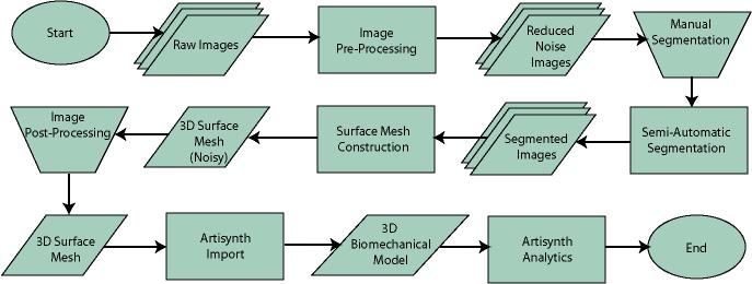 Figure 1. Process model for converting a raw image set into a 3D surface mesh for use in Artisynth. The data used in this project was a set of 130 TIFF (Tagged Image File Format) images resulting from a cranial CT scan. Each TIFF file was an image of a particular slice from the scan. 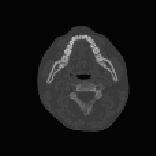 Figure 2. An image from a set of cranial CT scan slices. Other image formats may be used including RAW (raw, meaning unprocessed) and JPEG (Joint Photographic Experts Group). The resulting image set from a medical scan may contain noise. The noise may be due to movement in the patient or interference during the scan. This noise affects the images via erroneous pixels in the image data. In order to remove or at least reduce the noise, digital signal processing (DSP) must be performed on the images. A DSP algorithm must be chosen and the data corrected using an application that can run the DSP algorithm. Such applications include Matlab and Insight Segmentation and Registration Toolkit (ITK). ITK can import file formats such as JPEG, RAW, and TIFF [1]. Also, ITK can export Wavefront OBJ files which can be imported by Artisynth [2]. Segmentation is the process of isolating a particular component from its surroundings. In a 2D image, this can be thought of as tracing out a region of interest and removing it from its surroundings. There are many methods and algorithms for image segmentation, each one providing a balance between efficiency, accuracy, quality, and intended outcome. Some algorithms are designed for specific purposes such as face recognition or satellite images. The segmentation software investigated in this report were designed for - as one of their intended purposes medical image segmentation. The various methods for medical image segmentation can be categorized as manual, automatic, semi-automatic with manual editing before automation, and semi-automatic with manual editing after automation. This method requires the most time, patience, and medical knowledge out of all of the techniques. The person performing the segmentation will need to view each image slice (possibly hundreds of slices) and manually select a region to be segmented by tracing it out. Manual segmentation is extremely time consuming and, depending on the amount of physiological knowledge the person has, can even produce a less-accurate result compared with automatic segmentation. Another disadvantage of this technique is that it is difficult (or more likely impossible) to reproduce the segmentation again [3]. 2.3.2 Semi-Automatic With Manual Editing Before In this method, the user manually traces out a contour around the region of interest. The more accurate the trace is defined, the easier it is for the automation software to detect the intended region of interest. When the user completes the trace, the software will use a particular algorithm and run through the image slices determining the segmentation regions based on the selected region of interest. This method provides a good balance between the amount of effort put in and the degree of accuracy of the resulting segmentation. Also, even with small variations in the region of interest trace, the result is still similar thus providing high reproducibility [3]. For these reasons, this is the chosen method of segmentation that is used for analyzing segmentation software in this report. 2.3.3 Semi-Automatic With Manual Editing Afterwards This method starts by applying an automation technique such as a region growing or histogram-based algorithm. Following the automatic segmentation, the user manually alters the segmentation contours to the correct positions. A lot of effort is required in the manual phase of this method because the user must go through each image slice and change the segmentation contours. In order to change the contours to the correct positions, the user must have a good knowledge of the anatomy in the images. This is the other extreme of segmentation techniques. Fully automatic image segmentation is naturally the fastest technique to perform. By setting a few parameters, such as in global thresholding, the user can have the software run through the slices and automatically perform segmentation (in the case of global thresholding, this is performed through a histogram approach of each pixel) [4]. Unfortunately, as in the manual segmentation technique, the drawbacks outweigh the advantages for most applications. The trade-off with fully automatic image segmentation is that most algorithms are not sophisticated enough to segment out the intended region accurately or at all [3]. For some applications this technique may work well, such as segmenting out all skeletal regions. The large contrast between skeletal matter and the tissue and muscles surround it may be accurately detected by the automation software. However, the automation algorithm would most likely not be able to differentiate between a jaw and the rest of the skeleton. A surface mesh is a 3D representation of a set of 2D images. The result of creating this 3D representation is like stacking the 2D image slices on top of each other, one after another. Each pixel in the 2D image set has an x and y location in the image. For the 3D image, this translates to a voxel which uses an x, y, and z location for each point. The voxels are connected into polygons, most commonly triangles. The combination of all of these triangles from all of the voxels forms a 3D mesh. If a surface is applied over the mesh, it becomes a surface mesh. 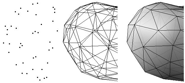 Figure 3. Point cloud to surface mesh translation. The segmented surface mesh will usually contain some inherent noise from the segmentation process. For example, there may be holes in the segmented mesh or extra, unwanted parts around the mesh. The goal of the post-processing is to fill in these holes and remove the unwanted parts. This part of the processing is usually done manually. Automated software may not be able to detect what is wanted and unwanted in a 3D surface mesh. If done manually, this may simply be removing unwanted parts of the mesh by selecting them and deleting them. Artisynth is a 3D modeling platform designed to simulate biomechanics, targeting the vocal tract and upper airway. Artisynth was primarily developed under the Electrical and Computer Engineering (EECE) and Computer Science (CS) departments at the University of British Columbia (UBC). One goal of Artisynth is to derive a complete vocal tract system that can produce accurate speech synthesis. 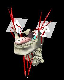 Figure 4. Jaw and tongue surface mesh model from Artisynth. A timeline can be created in Artisynth to allow for an animated simulation of biomechanical movement. For example, forces can be applied to a particle-spring system so as to move the lower jaw of a model up and down with applied constraints. Importing a reduced-noise, 3D surface mesh into Artiynth is the final step for the process defined in this report. The surface mesh can then be used as part of a system and can be analyzed. 3.0 SOFTWARE APPLICATIONSDigital signal processing (DSP) can be performed on the images to reduce the inherent noise. DSP applications include Matlab and a hybrid of Matlab and Insight Segmentation and Registration Toolkit (ITK) called MATITK (© 2007 Vincent Chu and Ghassan Hamarneh, Simon Fraser University). MATITK combines the medical imaging algorithms of Matlab with the medical imaging processing library of ITK. DSP is not investigated any further is this report. The algorithms and programming involved require a good knowledge of DSP and so is left for those who have taken a course or read textbooks on the subject. Amira (© 2007 Visage Imaging) can be used for image processing, visualization, segmentation and 3D reconstruction. For segmentation, there is the option of using a brush and painting in the region; a lasso to trace out a region; a magic wand for threshold segmentation; a snake algorithm and other manual and semi-automated techniques. The segmentation method used in this report with Amira was the semi-automatic threshold segmentation method. In this method, a region of interest was first traced out. The magic wand was then used to apply a minimum and maximum intensity threshold within the region of interest. The threshold was applied to all slices at once and the segmented result was constructed into a 3D mesh. This method was extremely quick and only took about 3 minutes. Accordingly, the reconstructed 3D mesh reflected this efficiency because it lacked proper definition and was quite jagged. A more thorough segmentation would have produced a better 3D mesh and a balance point should be found between manual time put in and accuracy achieved. 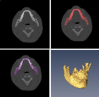 Figure 5. Segmentation of a jaw using Amiras threshold segmentation. 3D Doctor (© 2007 Able Software Corp.) is a 3D imaging application which can be used for image segmentation and 3D surface formation. The image inputs include CT, MRI, and PET cross-sectional images in TIFF, BMP and JPEG format (among others). 3D Doctor uses a combination of manual and automatic segmentation techniques. First, a region of interest can be traced out manually to select a region around the area that is to be segmented. Next, threshold segmentation is applied as an automated segmentation technique. The threshold determines the range of pixel intensities to select for segmentation within the region of interest. With the segmented section in each image complete, a mesh can be constructed with 3D Doctor. The amount of effort put in to segmenting the image for this report was minimal, and as a result the constructed 3D mesh is sub-optimal and contains a lot of holes and noise. However, with proper techniques and patience, the noise in the 3D mesh could be drastically reduced. 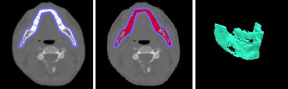 Figure 6. Image segmentation and mesh construction with 3D Doctor. Unfortunately, since the 3D Doctor application used in this report was a trial version, the mesh could not be saved for analysis. GemIdent (©2007 Board of Trustees of Leland Stanford Junior University) is used to identify regions of interest for colour segmentation [5]. This software could possibly be used as a histogram approach to segmentation. For example, bone matter may show up as white in a medical image, and the colour threshold could be set at white in order to segment out the bone matter. 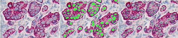 Figure 7. An example of colour segmentation using GemIdent [6]. The problem of using GemIdent is that it would not allow the TIFF images to be added to the project. This limitation ended the analyses of this software application, although further investigation may discover a solution. The VTK (Visualization Toolkit) and ITK (Insight Segmentation and Registration Toolkit) software libraries could be used for image segmentation. The problem that was encountered during this project is that I could not get either VTK or ITK to build properly. VTK/ITK can be run under Linux or Windows environments. Under Windows, which is what was used in this project, the libraries must be loaded into Visual Studio with the addition of the CMake program. During this project, Visual Studio 2008 Beta was used and would not compile VTK/ITK properly. ITK-SNAP is an application designed for manual and semi-automatic segmentation of MRI, CT and PET images. In semi-automatic mode, ITK-SNAP uses a level-set algorithm to segment anatomical structures [7]. 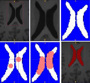 Figure 8. Image segmentation using the snake tool in ITK-SNAP. The image set used with ITK-SNAP was an example set that was included with the software. The major limitation with ITK-SNAP was that the TIFF images for this project could not be loaded directly. There was an option to load the images as RAW binary, but whenever this was tried with different parameters (such as image sizes), ITK-SNAP would crash and exit. The removal of noise from a segmented 3D mesh can be performed in any 3D graphics software that can open the format of the 3D mesh. Two software applications were analyzed Amira and Rhino. Rhino differs from Amira in that it does not have the capabilities of segmentation or mesh synthesis. Rhino is a 3D graphics design application and is used as a comparison between Amira and general 3D graphics software. It was found that Amira was a little more difficult to remove noise because it was slower loading, panning, and rotating the meshes. However, it was found that in some cases the user could select more detailed regions to remove than with Rhino. To begin removing noise from the mesh in Amira, one must select the green data icon of the image and then choose the Surface Editor from the Properties sidebar. Then, one can select the triangles that represent the noise and choose Edit->Delete highlighted faces from the Surface menu. An image of the result is below. 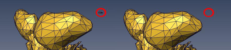 Figure 9. Removing noise from a 3D mesh using Amira. Rhino (© 2006 Robert McNeel and Associates) is a 3D graphics design application, and therefore lends itself better in terms of editing the meshes. The mesh format that was used during the analysis of Rhino was Wavefront OBJ. This is the same file format that can be exported from Amira and imported into Artisynth. To begin removing noise from the mesh in Rhino, the file is opened from the File menu. The mesh will display as a large group of triangles which cannot be individually selected. In order to be able to select each individual triangle (so that it can be removed if it is noise), one must first click on the mesh and then choose Groups->Ungroup from the Edit menu. Next, with the mesh still selected, one can choose Explode from the Edit menu. Now it is possible to select individual parts of the mesh and remove any noise that is present by simply selecting the part and pressing delete. An example image is below. 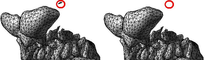 Figure 10. Removing noise from a 3D mesh using Rhino. Since Rhino was designed specifically for graphics editing, it was found to load meshes quicker, rotate and pan quicker, render meshes quicker, and was more user friendly than Amira for noise removal. 4.0 RECOMMENDATIONSAs a separate, related part of this project, an analysis of automated translation of meshes in Artisynth was investigated. This analysis involved having a 3D mesh imported into Artisynth with landmarks [8] attached and then automatically rotated into the correct position relative to another 3D mesh with landmarks attached. An example of this is to have an airway mesh automatically fit into position within a jaw and tongue model. One advantage of this is that it saves time there is no manual interaction for translating the mesh into place. Another advantage is that it improves accuracy landmarks and a placement algorithm are used, so the translational accuracy is proportional to the accuracy of the landmarks. In this project, this analysis was investigated but not fully implemented. The scope of implementation included writing Java code to import 5 airway mesh models into Artisynth; developing a sidebar which could turn each of the 5 airway models on or off; importing landmarks which were placed in Amira; and statically translating the models based on the imported landmark. 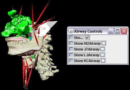 Figure 11. Automatic translation and Airway Controls in Artisynth. In the above figure, a landmark was placed at the tip of the displayed airway (coloured green, above the tongue) in Amira. When the airway mesh and the landmark were imported into Artisynth, the airway was translated based on the coordinates of the landmark. This was a static, contrived translation, but the idea could be implemented further. As a recommendation for future work, one could implement automatic mesh translation based on regression analysis using a least squares algorithm. For example, 3 landmarks could be placed on an airway mesh in Amira. These landmarks could be labeled numerically as landmarks 1, 2 and 3. On a jaw and tongue model, 3 landmarks could also be placed and labeled as landmarks 1, 2 and 3. When the airway mesh is imported into Artisynth, a regression algorithm could compute the placement of the airway mesh relative to the jaw and tongue model by computing the location where the distances between landmarks 1 to 1, 2 to 2, and 3 to 3 are minimized. 5.0 CONCLUSIONThis report investigated the process of converting a set of medical image slices into a segmented 3D mesh which could be imported into Artisynth. The steps that were found to be part of the process were:
Various software applications were identified, primarily for use in segmentation and post-processing. Many image segmentation applications were compared, each having its own set of drawbacks and advantages. These applications and others can be further analyzed to see if they might improve accuracy or efficiency. A recommendation for future work in Artisynth was identified as automatic translation of a surface mesh from relevant landmarks. This recommendation was briefly analyzed and an implementation of airway and landmark translation has been started. 6.0 REFERENCES[1] VTK FAQ. [Online]. Available: http://www.itk.org/Wiki/VTK_FAQ#What_image_file_formats_can_VTK_read_and_write.3F [Accessed October 20, 2007]. [2] VTK FAQ. [Online]. Available: http://www.itk.org/Wiki/VTK_FAQ#What_3D_file_formats_can_VTK_import_and_export.3F [Accessed October 20, 2007]. [3] Eilbert C. G. J., and McEachron, D., The variation in user drawn outlines on digital images: Effects on quantitative autoradiography. Compur. Med. Imag. Graphics, vol. 14, no. 5, pp. 331339, 1990. [4] Wu, T. Y., Image Segmentation: The First Step In 3-D Imaging, 1999. [Online]. Available: http://www.ablesw.com/3d-doctor/3dseg.html [Accessed November 3, 2007]. [5] Kapelner, A., Lee, P. P., and Holmes, S., An Interactive Statistical Image Segmentation and Visualization System, in Proceedings of the International Conference on Medical Information Visualisation - BioMedical Visualisation, vol. 4, pp 81-86, 2007. [6] Gemident, 2007. [Online]. Available: http://www.GemIdent.net [Accessed Nov. 2, 2007]. [7] Paul A. Yushkevich, Joseph Piven, Heather Cody Hazlett, Rachel Gimpel Smith, Sean Ho, James C. Gee, and Guido Gerig. User-guided 3D active contour segmentation of anatomical structures: Significantly improved efficiency and reliability. Neuroimage, Article In Press, 2006. [8] Stratemann, S. A., 3D Craniofacial Imaging: Airway and Craniofacial Morphology. PhD thesis, University of California at San Francisco, 2005. LIST OF ABBREVIATIONS
|
|
| View Edit Attributes History Attach Print Search Page last modified on December 04, 2007, at 12:36 PM | ||