3.6 Setting joint coordinates
As mentioned above, joint coordinate values are not fundamental representations of system state as they are in some other multibody systems, such as OpenSim. This means that they need to be inferred from the relative poses of the bodies connected by their joints. It also means that when setting the values for one or more coordinates, the poses of the surrounding bodies must be updated. In addition, it is usually necessary to also update the wrap paths of any MultiPointSpring or MultiPointMuscle components attached to the bodies. This functionality is provided by the CoordinateSetter class.
3.6.1 Using the CoordinateSetter
A CoordinateSetter is associated with a MechModel and can be created as follows:
A MechModel also maintains its own coordinate setter, which can be obtained as follows:
Once instantiated or obtained, the setter can be used to set coordinate values while ensuring that surrounding body poses and spring/muscle wrap surfaces are updated appropriately. It also handles situations involving closed kinematic chains where not all coordinate values are independent. Coordinate values can be set individually via the following methods:
| SetStatus setCoordinate ( JointCoordinateHandle handle, double value) |
Set coordinate described by handle to value (in radians for rotary coordinates). |
| SetStatus setCoordinate ( JointBase joint, int cidx, double value) |
Set coordinate described by joint and cidx to value (in radians for rotary coordinates). |
| SetStatus setCoordinateDeg ( JointCoordinateHandle handle, double value) |
Set coordinate to described by handle value (in degrees for rotary coordinates). |
| SetStatus setCoordinateDeg ( JointBase joint, int cidx, double value) |
Set coordinate described by joint and cidx to value (in degrees for rotary coordinates). |
Coordinates can be specified using either a JointCoordinateHandle handle (Section 3.4.7), or their joint and its index within it. Each method returns a CoordinateSetter.SetStatus to indicate the success of the operation. For open kinematic chains, coordinate setting always succeeds, but within a closed kinematic chain (Section 3.6.2) not all coordinates are independent and therefore some set operations may fail. All set requests are clipped to the coordinate’s range, if applicable.
Several coordinates can also be set simultaneously, using
| void request ( JointCoordinateHandle handle, double value) |
Queue request to set coordinate described by handle to value (in radians for rotary coordinates). |
| void request ( JointBase joint, int cidx, double value) |
Queue request to set coordinate described by joint and cidx to value (in radians for rotary coordinates). |
| void requestDeg ( JointCoordinateHandle handle, double value) |
Queue request to set coordinate described by handle to value (in degrees for rotary coordinates). |
| void requestDeg ( JointBase joint, int cidx, double value) |
Queue request to set coordinate described by joint and cidx to value (in degrees for rotary coordinates). |
| SetStatus setCoordinates() |
Apply all set requests. |
| void clearRequests() |
Clear all outstanding set requests. |
The request() methods queue specific coordinate set requests, and then setCoordinates() attempts to satisfy them all simultaneously, returning a CoordinateSetter.SetStatus to indicate its success.
As an example, the following code could be used to set coordinates at the end of the build() method for the multijointed arm example of Section 3.5.16:
Joint coordinates can also be set interactively in the GUI using a coordinate panel (Section 5.1.4), and the CoordinatePanel class provides access to its underlying CoordinateSetter and convenience wrappers for some of its methods.
3.6.2 Coordinates in closed kinematic chains
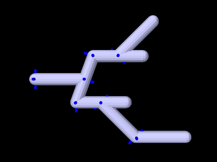
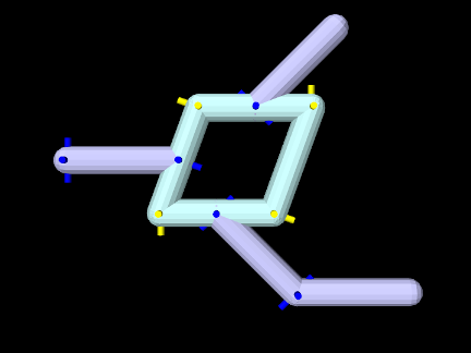
Coordinates can be assigned arbitrarily for any joint which is part of an open kinematic chain forming a linear or tree-shaped structure (Figure 3.28). However, this is not true for closed kinematic chains, in which joints (and possibly other constraints) connect a set of bodies into a loop (Figure 3.29). Closed chains also present challenges for simulation, as discussed in Section 3.4.10.
The formation of kinematic loops reduces the number of degrees of freedom and reduces the number of joint coordinates which can be set independently, in a manner that depends on the joints and connection topology. For the joints in the loop of Figure 3.29, only two of the eight coordinates can be set independently. It is possible (and typical) for a kinematic loop to be embedded within a kinematic structure that is otherwise open, and this is true in Figure 3.29, where the non-loop joints (shown in dark blue) can still be positioned arbitrarily.
When using a CoordinateSetter to set several coordinates at once within a kinematic loop, the request will only partially succeed if the number of coordinates being set exceeds the number of independent coordinates. Requests may also fail if some of the dependent coordinates encounter a range limit. For example, the four bar linkage of Section 3.4.10 has four joints but only one degree of freedom, and so trying to set more than one coordinate will fail, which can be verified by checking the status object returned by setCoordinates():
In general, set requests result in a coordinate either being free (and therefore set to the requested value), dependent (on other coordinate values), or limited (independent but limited because of singularities or dependent coordinate joint limits). Also, very occasionally, if the linkage is near a kinematic singularity, the solver may fail to converge and no coordinates will be set exactly as requested.
SetStatus supplies a number of methods to query coordinate set status, including:
| int numCoordinates() |
Number of coordinates requested to be set. |
|---|---|
| List<JointCoordinateHandle> getCoordinates() |
Query the coordinates requested to be set. |
| boolean converged() |
Queries if the solve converged. |
| int numFree() |
Number of coordinates that are free. |
| boolean isFree (JointCoordinateHandle handle) |
Queries if a coordinate is free. |
| int numFree() |
Number of coordinates that are limited. |
| boolean isLimited (JointCoordinateHandle handle) |
Queries if a coordinate is limited. |
| int numDependent() |
Number of coordinates that are dependent. |
| boolean isDependent (JointCoordinateHandle handle) |
Queries if a coordinate is dependent. |
![[LOGO]](data:image/png;base64,iVBORw0KGgoAAAANSUhEUgAAAAsAAAAOCAYAAAD5YeaVAAAAAXNSR0IArs4c6QAAAAZiS0dEAP8A/wD/oL2nkwAAAAlwSFlzAAALEwAACxMBAJqcGAAAAAd0SU1FB9wKExQZLWTEaOUAAAAddEVYdENvbW1lbnQAQ3JlYXRlZCB3aXRoIFRoZSBHSU1Q72QlbgAAAdpJREFUKM9tkL+L2nAARz9fPZNCKFapUn8kyI0e4iRHSR1Kb8ng0lJw6FYHFwv2LwhOpcWxTjeUunYqOmqd6hEoRDhtDWdA8ApRYsSUCDHNt5ul13vz4w0vWCgUnnEc975arX6ORqN3VqtVZbfbTQC4uEHANM3jSqXymFI6yWazP2KxWAXAL9zCUa1Wy2tXVxheKA9YNoR8Pt+aTqe4FVVVvz05O6MBhqUIBGk8Hn8HAOVy+T+XLJfLS4ZhTiRJgqIoVBRFIoric47jPnmeB1mW/9rr9ZpSSn3Lsmir1fJZlqWlUonKsvwWwD8ymc/nXwVBeLjf7xEKhdBut9Hr9WgmkyGEkJwsy5eHG5vN5g0AKIoCAEgkEkin0wQAfN9/cXPdheu6P33fBwB4ngcAcByHJpPJl+fn54mD3Gg0NrquXxeLRQAAwzAYj8cwTZPwPH9/sVg8PXweDAauqqr2cDjEer1GJBLBZDJBs9mE4zjwfZ85lAGg2+06hmGgXq+j3+/DsixYlgVN03a9Xu8jgCNCyIegIAgx13Vfd7vdu+FweG8YRkjXdWy329+dTgeSJD3ieZ7RNO0VAXAPwDEAO5VKndi2fWrb9jWl9Esul6PZbDY9Go1OZ7PZ9z/lyuD3OozU2wAAAABJRU5ErkJggg==)