3.7 Frame springs
Another way to connect two rigid bodies together is to use a frame spring, which is a six dimensional spring that generates restoring forces and moments between coordinate frames.
3.7.1 Frame spring coordinate frames
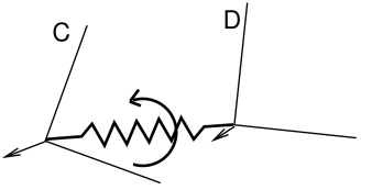
The basic idea of a frame spring is shown in Figure
3.30. It generates restoring forces and moments on
two frames C and D which are a function of ![]() and
and ![]() (the spatial velocity of frame D with respect to frame C).
(the spatial velocity of frame D with respect to frame C).
Decomposing forces into stiffness and damping terms, the force
![]() and moment
and moment ![]() acting on C can be expressed as
acting on C can be expressed as
| (3.24) |
where the translational and rotational forces ![]() ,
, ![]() ,
,
![]() , and
, and ![]() are general functions of
are general functions of ![]() and
and
![]() .
.
The forces acting on D are equal and opposite, so that
| (3.25) |
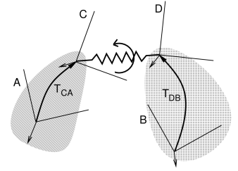
If frames C and D are attached to a pair of rigid bodies A and B, then
a frame spring can be used to connect them in a manner analogous to a
joint. As with joints, C and D generally do not coincide with the body
frames, and are instead offset from them by fixed transforms ![]() and
and ![]() (Figure 3.31).
(Figure 3.31).
For historical reasons, the default behavior for frame springs is to base the restoring forces on
and
, as per (3.24). However, it may be more convenient to instead use
and
and compute the force
and moment
acting on frame D:
(3.26) For example, using
3.7.2 Frame materials
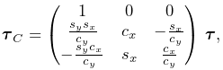
The restoring forces (3.24) generated in a frame spring depend on the frame material associated with the spring. Frame materials are defined in the package artisynth.core.materials, and are subclassed from FrameMaterial. The most basic type of material is a LinearFrameMaterial, in which the restoring forces are determined from
where ![]() gives the small angle approximation of the
rotational components of
gives the small angle approximation of the
rotational components of ![]() with respect to the
with respect to the ![]() ,
, ![]() , and
, and
![]() axes, and
axes, and
 |
||
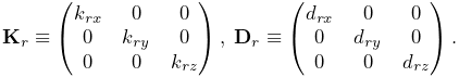 |
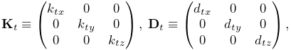
are the stiffness and damping matrices. The diagonal values defining
each matrix are stored in the 3-dimensional vectors ![]() ,
, ![]() ,
,
![]() , and
, and ![]() which are exposed as the stiffness, rotaryStiffness, damping, and rotaryDamping properties of
the material. Each of these specifies stiffness or damping values
along or about a particular axis. Specifying different values for
different axes will result in anisotropic behavior.
which are exposed as the stiffness, rotaryStiffness, damping, and rotaryDamping properties of
the material. Each of these specifies stiffness or damping values
along or about a particular axis. Specifying different values for
different axes will result in anisotropic behavior.
Other frame materials offering nonlinear behavior may be defined in artisynth.core.materials.
3.7.2.1 PowerFrameMaterial
A useful alternative to LinearFrameMaterial is PowerFrameMaterial, which computes restoring forces along each of the translational and rotational directions according to a power law of the form
| (3.27) |
where ![]() is a stiffness,
is a stiffness, ![]() is displacement, and
is displacement, and ![]() is an exponent
in the range
is an exponent
in the range ![]() . It is also possible to specify both upper and
lower deadbands,
. It is also possible to specify both upper and
lower deadbands, ![]() and
and ![]() , such that if
, such that if ![]() is the true
displacement,
is the true
displacement, ![]() is computed according to
is computed according to
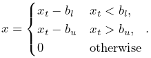 |
(3.28) |
PowerFrameMaterial effects the same damping behavior as LinearFrameMaterial.
If rotational deadbands are specified, the rotational displacement may be large
enough that the small angle approximation used for LinearFrameMaterial no longer applies. Therefore, rotational displacements are
computed as the three x-y-z Tait-Bryan angles of ![]() . The use of
these finite displacement angles introduces a coupling such that if
. The use of
these finite displacement angles introduces a coupling such that if ![]() is
the nominal moment produced by applying (3.27) and
(3.28) to each of the
three rotational angles, the actual resulting moment
is
the nominal moment produced by applying (3.27) and
(3.28) to each of the
three rotational angles, the actual resulting moment ![]() is
is
 |
(3.29) |
where ![]() ,
, ![]() ,
, ![]() ,
, ![]() are the sines and cosines of the x and y
rotations. The coupling is associated with the non-commutativity of rotations and
the fact that the x-y-z angles have a singularity when the y rotation
approaches
are the sines and cosines of the x and y
rotations. The coupling is associated with the non-commutativity of rotations and
the fact that the x-y-z angles have a singularity when the y rotation
approaches ![]() . This appears as the division by
. This appears as the division by ![]() in
(3.29), and so care should be taken to avoid such
orientations.
in
(3.29), and so care should be taken to avoid such
orientations.
The parameters controlling the behavior of PowerFrameMaterial can be set independently for each of the six translational and rotational displacements, using the following properties, each of which is described by a three-vector:
| Property | Description | |
|---|---|---|
| stiffness | translational stiffness | |
| exponents | translational exponents | |
| upperDeadband | upper deadband for translations | |
| lowerDeadband | lower deadband for translations | |
| damping | translational damping | |
| rotaryStiffness | rotational stiffness | |
| rotaryExponents | rotational exponents | |
| upperRotaryDeadband | upper deadband for rotations | |
| lowerRotaryDeadband | lower deadband for rotations | |
| rotaryDamping | rotational damping |
Each of these has a default value of ![]() , except for the exponents,
which have a default value of
, except for the exponents,
which have a default value of ![]() .
.
 |
 |
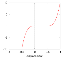 |
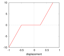
If used with exponents of 1 and no deadbands, PowerFrameMaterial behaves
like LinearFrameMaterial with finite rotation displacements. Otherwise,
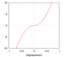
Figure 3.32 illustrates some of the force-displacement
curves that can be produced. Using a power ![]() (rightmost panels) has the
advantage of producing a curve that is differentiable. However, the forces
grow more slowly for smaller displacements; a cubic force (right panel) almost
behaves as if it has a small deadband, even with
(rightmost panels) has the
advantage of producing a curve that is differentiable. However, the forces
grow more slowly for smaller displacements; a cubic force (right panel) almost
behaves as if it has a small deadband, even with ![]() .
.
An important application of PowerFrameMaterial is creating one-sided
force behaviors by setting ![]() or
or ![]() to sufficiently low or high values.
to sufficiently low or high values.
3.7.3 Creating frame springs
Frame springs are implemented by the class
FrameSpring. Creating a frame
spring generally involves instantiating this class, and then setting
the material, the bodies A and B, and the transforms ![]() and
and
![]() .
.
A typical construction sequence might look like this:
The material is set using
setMaterial().
The example above uses a LinearFrameMaterial, created with a
constructor that sets ![]() ,
, ![]() ,
, ![]() , and
, and ![]() to uniform
isotropic values specified by kt, kr, dt, and dr.
to uniform
isotropic values specified by kt, kr, dt, and dr.
The bodies and transforms can be set in the same manner as for joints
(Section 3.4.3), with the
methods
setFrames(bodyA,bodyB,TDW)
and
setFrames(bodyA,TCA,bodyB,TDB)
assuming the role of the setBodies() methods used for joints.
The former takes D specified in world coordinates and computes
![]() and
and ![]() assuming that there is no initial spring
displacement (i.e., that
assuming that there is no initial spring
displacement (i.e., that ![]() ), while the latter allows
), while the latter allows
![]() and
and ![]() to be specified explicitly with
to be specified explicitly with ![]() assuming whatever value is implied.
assuming whatever value is implied.
Frame springs and joints are often placed together, using the same
transforms ![]() and
and ![]() , with the spring providing
restoring forces to help keep the joint within prescribed bounds.
, with the spring providing
restoring forces to help keep the joint within prescribed bounds.
As with joints, a frame spring can be connected to only a single body, by specifying frameB as null. Frame B is then taken to be the world coordinate frame W.
3.7.4 Example: two bodies connected by a frame spring
A simple model showing two simplified lumbar vertebrae, modeled as rigid bodies and connected by a frame spring, is defined in
artisynth.demos.tutorial.LumbarFrameSpring
The definition for the entire model class is shown here:
For convenience, the code to create and add each vertebrae is wrapped into the method addBone() defined at lines 27-32. This method takes two arguments: the MechModel to which the bone should be added, and the name of the bone. Surface meshes for the bones are located in .obj files located in the directory ../mech/geometry relative to the source directory for the model itself. PathFinder.getSourceRelativePath() is used to find a proper path to this directory (see Section 2.6) given the model class type (LumbarFrameSpring.class), and this is stored in the static string geometryDir. Within addBone(), the directory path and the bone name are used to create a path to the bone mesh itself, which is in turn used to create a PolygonalMesh (line 28). The mesh is then used in conjunction with a density to create a rigid body which is added to the MechModel (lines 29-30) and returned.
The build() method begins by creating and adding a MechModel, specifying a low value for gravity, and setting the rigid
body damping properties frameDamping and rotaryDamping (lines 37-41). (The damping parameters are needed
here because the frame spring itself is created with no damping.)
Rigid bodies representing the vertebrae lumbar1 and lumbar2 are then created by calling addBone() (lines 44-45),
lumbar1 is translated by setting the origin of its pose to
![]() , and lumbar2 is set to be fixed by making
it non-dynamic (line 47).
, and lumbar2 is set to be fixed by making
it non-dynamic (line 47).
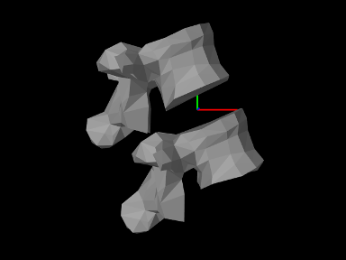
At this point in the construction, if the model were to be loaded, it
would appear as in Figure 3.34. To change
the viewpoint to that seen in Figure 3.33, we
rotate the entire model about the ![]() axis (line 50). This is done
using
transformGeometry(X), which transforms the geometry of an entire
model using a rigid or affine transform. This method is
described in more detail in Section 4.7.
axis (line 50). This is done
using
transformGeometry(X), which transforms the geometry of an entire
model using a rigid or affine transform. This method is
described in more detail in Section 4.7.
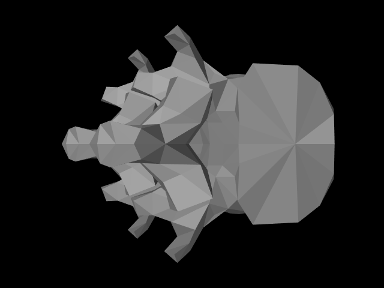
The frame spring is created and added at lines 54-59, using the methods described in Section 3.7.3, with frame D set to the (initial) pose of lumbar1.
Render properties are set starting at line 62. By default, a frame spring renders as a pair of red, green, blue coordinate axes showing frames C and D, along with a line connecting them. The line width and the color of the connecting line are controlled by the line render properties lineWidth and lineColor, while the length of the coordinate axes is controlled by the special frame spring property axisLength.
To run this example in ArtiSynth, select All demos > tutorial > LumbarFrameSpring from the Models menu. The model should load and initially appear as in Figure 3.33. Running the model (Section 1.5.3) will cause lumbar1 to fall slightly under gravity until the frame spring arrests the motion. To get a sense of the spring’s behavior, one can interactively apply forces to lumbar1 using the pull tool (see the section “Pull Manipulation” in the ArtiSynth User Interface Guide).
![[LOGO]](data:image/png;base64,iVBORw0KGgoAAAANSUhEUgAAAAsAAAAOCAYAAAD5YeaVAAAAAXNSR0IArs4c6QAAAAZiS0dEAP8A/wD/oL2nkwAAAAlwSFlzAAALEwAACxMBAJqcGAAAAAd0SU1FB9wKExQZLWTEaOUAAAAddEVYdENvbW1lbnQAQ3JlYXRlZCB3aXRoIFRoZSBHSU1Q72QlbgAAAdpJREFUKM9tkL+L2nAARz9fPZNCKFapUn8kyI0e4iRHSR1Kb8ng0lJw6FYHFwv2LwhOpcWxTjeUunYqOmqd6hEoRDhtDWdA8ApRYsSUCDHNt5ul13vz4w0vWCgUnnEc975arX6ORqN3VqtVZbfbTQC4uEHANM3jSqXymFI6yWazP2KxWAXAL9zCUa1Wy2tXVxheKA9YNoR8Pt+aTqe4FVVVvz05O6MBhqUIBGk8Hn8HAOVy+T+XLJfLS4ZhTiRJgqIoVBRFIoric47jPnmeB1mW/9rr9ZpSSn3Lsmir1fJZlqWlUonKsvwWwD8ymc/nXwVBeLjf7xEKhdBut9Hr9WgmkyGEkJwsy5eHG5vN5g0AKIoCAEgkEkin0wQAfN9/cXPdheu6P33fBwB4ngcAcByHJpPJl+fn54mD3Gg0NrquXxeLRQAAwzAYj8cwTZPwPH9/sVg8PXweDAauqqr2cDjEer1GJBLBZDJBs9mE4zjwfZ85lAGg2+06hmGgXq+j3+/DsixYlgVN03a9Xu8jgCNCyIegIAgx13Vfd7vdu+FweG8YRkjXdWy329+dTgeSJD3ieZ7RNO0VAXAPwDEAO5VKndi2fWrb9jWl9Esul6PZbDY9Go1OZ7PZ9z/lyuD3OozU2wAAAABJRU5ErkJggg==)