8.9 Tips and limitations
This section describes practical tips that can employed when using ArtiSynth’s contact simulation, together with some of its limitations.
8.9.1 Contact jitter
ArtiSynth’s attempt to resolve the interpenetration of colliding bodies may sometimes cause a jittering behavior around the colliding area, as the surface collides, separates, and re-collides. This can usually be stabilized by maintaining a certain interpenetration distance during contact. This distance is controlled by the MechModel property penetrationTol. ArtiSynth attempts to compute a suitable default value for this property, but for some applications it may be necessary to control the value explicitly using the MechModel methods
8.9.2 Passing through objects
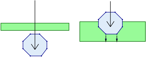
The ArtiSynth collision detection mechanism is static, which means that mesh intersections are computed at a fixed point in time and do not presently utilize velocity information. This means that if the colliding objects are fast enough or thin enough, it is possible for them to pass completely through each other during a simulation step (Figure 8.21, left). Similarly, even if objects do not pass completely through each other, the penetration may be large enough for contacts to be established with the wrong side (Figure 8.21, right).
When this happens, there are two straightforward solutions:
-
1.
Reduce the simulation step size.
-
2.
Increase the thickness of one or more of the colliding meshes. This option is facilitated by the fact that, as mentioned in Section 8.3, collision meshes can be independent of a collidable’s physical geometry.
The problem of collidables passing through each other can be particularly acute in the case of shell elements, and consequently collisions involving shell elements are not fully supported. However, collisions involving shell elements will work in some circumstances, as described in Section 8.1.4.
8.9.3 Stray vertices
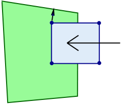
The stray vertex problem sometimes occurs when vertex penetration contact is used with objects with sharp edges. Because vertex penetration contacts are determined by finding the nearest face to each vertex on the opposing mesh, this may sometimes cause an inappropriate face to be selected if penetration is deep enough and near a sharp turn in the opposing mesh (Figure 8.22).
Possible solutions include:
-
1.
Reduce the simulation step size.
-
2.
Use the VERTEX_EDGE_PENETRATION contact method (Section 8.4.1.3).
-
3.
Adjust the mesh geometry or increase the mesh resolution; higher mesh resolutions will increase the number of contacts and reduce the impact of stray vertices.
8.9.4 Coulomb friction and stability
ArtiSynth uses a “box” friction approximation [10] to compute Coulomb (dry) friction, which allows for a less expensive and more robust computation at the expense of some accuracy. Box friction computes friction forces in two orthogonal directions in the plane perpendicular to the contact normal, using a fixed normal force taken from the previous solve, instead of employing the more detailed polyhedralized friction cones commonly used in multibody dynamics [1, 20]. The resulting linear complementarity problem is convex and hence more easily solved. Errors can be minimized by ensuring that one of the friction directions is parallel to the tangential contact velocity.
By default, friction forces are computed after the main velocity solve, in a secondary solve that does not use implicit integration techniques. This reduces compute time and works well for rigid bodies, or for FEM models when the friction forces are relatively small (which they often are in biomechanical applications). However, applications involving FEM models and large friction forces may suffer from instability. An example of this might be an FEM model resting on an inclined plane and relying on friction to remain stationary under a large load. To handle such situations, one can enable implicit friction integration by setting the useImplicitFriction property in MechModel; this can be done in code using the MechModel methods
At the time of this writing, implicit friction integration is a new ArtiSynth feature, and should be considered to be in beta testing.
When using implicit friction integration, if redundant contacts arise (typically between rigid bodies), it may be necessary to regularize both the contact constraints, using one of the methods described in Section 8.7, as well as the friction constraints, by setting the stictionCreep property of either the collision manager or behavior to a non-zero value, as described in Section 8.2.1.
![[LOGO]](data:image/png;base64,iVBORw0KGgoAAAANSUhEUgAAAAsAAAAOCAYAAAD5YeaVAAAAAXNSR0IArs4c6QAAAAZiS0dEAP8A/wD/oL2nkwAAAAlwSFlzAAALEwAACxMBAJqcGAAAAAd0SU1FB9wKExQZLWTEaOUAAAAddEVYdENvbW1lbnQAQ3JlYXRlZCB3aXRoIFRoZSBHSU1Q72QlbgAAAdpJREFUKM9tkL+L2nAARz9fPZNCKFapUn8kyI0e4iRHSR1Kb8ng0lJw6FYHFwv2LwhOpcWxTjeUunYqOmqd6hEoRDhtDWdA8ApRYsSUCDHNt5ul13vz4w0vWCgUnnEc975arX6ORqN3VqtVZbfbTQC4uEHANM3jSqXymFI6yWazP2KxWAXAL9zCUa1Wy2tXVxheKA9YNoR8Pt+aTqe4FVVVvz05O6MBhqUIBGk8Hn8HAOVy+T+XLJfLS4ZhTiRJgqIoVBRFIoric47jPnmeB1mW/9rr9ZpSSn3Lsmir1fJZlqWlUonKsvwWwD8ymc/nXwVBeLjf7xEKhdBut9Hr9WgmkyGEkJwsy5eHG5vN5g0AKIoCAEgkEkin0wQAfN9/cXPdheu6P33fBwB4ngcAcByHJpPJl+fn54mD3Gg0NrquXxeLRQAAwzAYj8cwTZPwPH9/sVg8PXweDAauqqr2cDjEer1GJBLBZDJBs9mE4zjwfZ85lAGg2+06hmGgXq+j3+/DsixYlgVN03a9Xu8jgCNCyIegIAgx13Vfd7vdu+FweG8YRkjXdWy329+dTgeSJD3ieZ7RNO0VAXAPwDEAO5VKndi2fWrb9jWl9Esul6PZbDY9Go1OZ7PZ9z/lyuD3OozU2wAAAABJRU5ErkJggg==)