8.7 Contact regularization
Contact regularization is a technique in which contact constraints are made “soft” by adding compliance and damping. This means that they no longer remove DOFs from the system, and so overconstraining cannot occur, but contact penetration is no longer strictly enforced and there may be an increase in the computation time required for the simulation.
8.7.1 Compliant contact
Compliant contact is a simple form of regularization that is analogous
to that used for joints and connectors, discussed in Section
3.4.9. Compliance and damping parameters ![]() and
and
![]() can be specified between any two collidables, with
can be specified between any two collidables, with ![]() being the
inverse of a corresponding contact stiffness
being the
inverse of a corresponding contact stiffness ![]() , such the
contact forces
, such the
contact forces ![]() acting along each contact normal are given by
acting along each contact normal are given by
| (8.1) |
where ![]() is the contact penetration distance and is negative
when penetration occurs. Contact forces act to push the contacting
bodies apart, so if body A is penetrating body B and the contact
normal
is the contact penetration distance and is negative
when penetration occurs. Contact forces act to push the contacting
bodies apart, so if body A is penetrating body B and the contact
normal ![]() is directed toward A, the forces acting on A and B
at the contact point will be
is directed toward A, the forces acting on A and B
at the contact point will be ![]() and
and ![]() , respectively.
Since
, respectively.
Since ![]() is the inverse of the contact stiffness
is the inverse of the contact stiffness ![]() , a value of
, a value of ![]() (the default) implies “infinitely” stiff contact
constraints. Compliance is enabled whenever the compliance is set
to a value greater than 0, with stiffness decreasing as compliance
increases.
(the default) implies “infinitely” stiff contact
constraints. Compliance is enabled whenever the compliance is set
to a value greater than 0, with stiffness decreasing as compliance
increases.
Compliance can be enabled by setting the compliance and damping properties of either the collision manager or the
CollisionBehavior for a
specific collision pair; these properties correspond to ![]() and
and ![]() in
(8.1). While it is not required to set the damping
property, it is usually desirable to set it to a value that
approximates critical damping in order to prevent “bouncing” contact
behavior. Compliance and damping can be set in the GUI by editing the
properties of either the collision manager or a specific collision
behavior, or set in code using the accessor methods
in
(8.1). While it is not required to set the damping
property, it is usually desirable to set it to a value that
approximates critical damping in order to prevent “bouncing” contact
behavior. Compliance and damping can be set in the GUI by editing the
properties of either the collision manager or a specific collision
behavior, or set in code using the accessor methods
as is illustrated by the following code fragments:
An important question is what values to choose for compliance and
damping. At present, there is no automatic way to determine these, and
so some experimental parameter tuning is often necessary. With regard
to the contact stiffness ![]() , appropriate values will depend on the
desired maximum penetration depth and other loadings acting on the
body. The mass of the collidable bodies may also be relevant if one
wants to control how fast the contact stabilizes. (The mass of every
CollidableBody can be
determined by its getMass() method.) Since
, appropriate values will depend on the
desired maximum penetration depth and other loadings acting on the
body. The mass of the collidable bodies may also be relevant if one
wants to control how fast the contact stabilizes. (The mass of every
CollidableBody can be
determined by its getMass() method.) Since ![]() acts on a
per-contact basis, the resulting total force will increase with the
number of contacts. Once
acts on a
per-contact basis, the resulting total force will increase with the
number of contacts. Once ![]() is determined, the compliance value
is determined, the compliance value ![]() is simply the inverse:
is simply the inverse: ![]() .
.
Given ![]() , the damping
, the damping ![]() can then be estimated based on the desired
damping ratio
can then be estimated based on the desired
damping ratio ![]() , using the formula
, using the formula
| (8.2) |
where ![]() is the combined mass of the collidable bodies (or the mass
of one body if the other is non-dynamic). Typically, the desired
damping will be close to critical damping, for which
is the combined mass of the collidable bodies (or the mass
of one body if the other is non-dynamic). Typically, the desired
damping will be close to critical damping, for which ![]() .
.
An example that allows a user to play with contact regularization is given in Section 8.5.1.
8.7.2 Contact force behaviors
When regularizing contact through compliance, as described in
Section 8.6, the forces ![]() at each
contact are explicitly determined as per (8.1). As
a broader alternative to this, ArtiSynth allows applications to
specify a contact force behavior,
which allows
at each
contact are explicitly determined as per (8.1). As
a broader alternative to this, ArtiSynth allows applications to
specify a contact force behavior,
which allows ![]() to be computed as a more generalized function of
to be computed as a more generalized function of
![]() :
:
| (8.3) |
where ![]() and
and ![]() are functions returning the elastic force and
the damping coefficient. The corresponding compliance is then a local
function of
are functions returning the elastic force and
the damping coefficient. The corresponding compliance is then a local
function of ![]() given by
given by ![]() (which is the inverse of the
local stiffness).
(which is the inverse of the
local stiffness).
Because
is negative during contact,
should also be negative.
, on the other hand, should be positive, so that the damping acts to reduce
.
Contact force behaviors are implemented as subclasses of the abstract class ContactForceBehavior. To enable them, the application sets the forceBehavior property of the CollisionBehavior controlling the contact interaction, using the method
A ContactForceBehavior must implement the method computeResponse() to compute the contact force, compliance and damping at each contact:
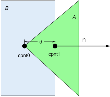
The arguments to this method supply specific information about the contact (see Figure 8.17):
- fres
-
An array of length three that returns the contact force, compliance and damping in its first, second and third entries. The contact force is the
shown in (8.3), the compliance
is  , and the damping is .
 - dist
-
The penetration distance
(the value of which is negative). - cpnt0, cpnt1
-
ContactPoint objects containing information about the two points associated with the contact (Figure 8.17), including each point’s position (returned by getPoint()) and associated vertices and weights (returned by numVertices(), getVertices(), and getWeights()).
- nrml
-
The contact normal
 .
. - contactArea
-
Average area per contact, computed by dividing the total area of the contact region by the number of penetrating vertices. This information is only available if the colliderType property of the collision behavior is set to AJL_CONTOUR (Section 8.2.1); otherwise, contactArea will be set to -1.
A collision force behavior may use its computeResponse() method
to calculate the force, compliance and damping in any desired way. As
per equation (8.3), these quantities are
functions of the penetration distance ![]() , supplied by the argument
dist.
, supplied by the argument
dist.
A very simple instance of ContactForceBehavior that just recreates the contact compliance of (8.1) is shown below:
This example uses only the penetration distance information supplied by dist, dividing it by the compliance to determine the contact force. Since dist is negative when the collidables are interpenetrating, the returned contact force will also be negative.
8.7.2.1 Computing forces based on pressure
Often, such as when implementing elastic foundation contact
(Section 8.7.3), the contact force
behavior is expressed in terms of pressure, given as a
function of ![]() :
:
| (8.4) |
In that case, the contact force ![]() is determined by multiplying
is determined by multiplying
![]() by the local area
by the local area ![]() associated with the contact:
associated with the contact:
| (8.5) |
Since
is negative as well.
To find the area ![]() within the computeResponse() method, one
has two options:
within the computeResponse() method, one
has two options:
-
A)
Compute an estimate of the local contact area surrounding the contact, as discussed below. This may be the more appropriate option if the colliding mesh vertices are not uniformly spaced, or if the contactArea argument is undefined because the AJL_CONTOUR collider (Section 8.4.2) is not being used.
-
B)
Use the contactArea argument if it is defined. This gives an accurate estimate of the per-contact area on the assumption that the colliding mesh vertices are uniformly distributed. contactArea will be defined when using the AJL_CONTOUR collider (Section 8.4.2); otherwise, it will be set to -1.
For option (A), ContactForceBehavior provides the convenience method computeContactArea(cpnt0,cpnt1,nrml), which estimates the local contact area given the contact points and normal. If the above example of computeResponse() is modified so that the stiffness parameter controls pressure instead of force, then we obtain the following:
computeContactArea() only works for vertex penetration contact (Section 8.4.1.2), and will return -1 otherwise. That’s because it needs the contact points’ vertex information to compute the area. In particular, for vertex penetration contact, it associates the vertex with 1/3 of the area of each of its surrounding faces.
When computing contact forces, care must also be taken to consider whether the vertex penetrations are being computed for both colliding surfaces (two-way contact, Section 8.4.1.2). This means that forces are essentially being computed twice - once for each side of the penetrating surface. For forces based on pressure, the resulting contact forces should then be halved. To determine when two-way contact is in effect, the flags argument can be examined for the flag TWO_WAY_CONTACT:
8.7.3 Elastic foundation contact
ArtiSynth supplies a built-in contact force behavior, LinearElasticContact, that implements elastic foundation contact (EFC) based on a linear material law as described in [3]. By default, the contact pressures are computed from
| (8.6) |
where ![]() is Young’s modulus,
is Young’s modulus, ![]() is Poisson’s ratio,
is Poisson’s ratio, ![]() is the
contact penetration distance, and
is the
contact penetration distance, and ![]() is the foundation layer
thickness. (Note that both
is the foundation layer
thickness. (Note that both ![]() and
and ![]() are negated relative to the
formulation in [3] because we assume
are negated relative to the
formulation in [3] because we assume ![]() during
contact.) The use of the
during
contact.) The use of the ![]() function helps ensure that contact
does not penetrate the foundation layer. However, to ensure robustness
in case contact does penetrate the layer (or comes close to
doing so), the pressure relationship is linearized (with a steep
slope) whenever
function helps ensure that contact
does not penetrate the foundation layer. However, to ensure robustness
in case contact does penetrate the layer (or comes close to
doing so), the pressure relationship is linearized (with a steep
slope) whenever ![]() , where
, where ![]() is the minimum thickness
ratio controlled by the LinearElasticContact property minThicknessRatio.
is the minimum thickness
ratio controlled by the LinearElasticContact property minThicknessRatio.
Alternatively, if a strictly linear pressure relationship is desired, this can be achieved by setting the property useLogDistance to false. The pressure relationship then becomes
| (8.7) |
where again ![]() will be negative when
will be negative when ![]() .
.
Damping forces ![]() can be computed in one of two ways: either
with
can be computed in one of two ways: either
with ![]() set to a constant
set to a constant ![]() such that
such that
| (8.8) |
or with ![]() set to a multiple of
set to a multiple of ![]() and the magnitude of the
elastic contact force
and the magnitude of the
elastic contact force ![]() , such that
, such that
| (8.9) |
The latter is compatible with the EFC damping used by OpenSim (equation 24 in [22]).
Elastic foundation contact assumes the use of vertex penetration contact (Section 8.4.1) to achieve correct results; otherwise, a runtime error may result.
LinearElasticContact exports several properties to control the force response described above:
- youngsModulus
-
- poissonsRatio
-
- thickness
-
- minThicknessRatio
-
 value such that (8.6) is linearized if
 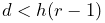 .
The default value is 0.01.
.
The default value is 0.01. - dampingFactor
-
- dampingMethod
-
An enum of type ElasticContactBase.DampingMethod, for which DIRECT and FORCE cause damping to be implemented using (8.8) and (8.9), respectively. The default value is DIRECT.
- useLogDistance
-
- useLocalContactArea
-
A boolean, which if true causes contact areas to be estimated from the vertex of the penetrating contact point (option A in Section 8.7.2.1). The default value is true.
8.7.4 Example: elastic foundation contact of a ball in a bowl
A simple example of elastic foundation contact is defined by the model
artisynth.demos.tutorial.ElasticFoundationContact
This implements EFC between a spherical ball and a bowl into which it is dropped. Pressure rendering is enabled (Section 8.5.3), and the bowl is made transparent, allowing the contact pressure to be viewed as the ball moves about.
The source code for the build method is shown below:
The demo first creates the ball and the bowl as rigid bodies (lines 6-26), with the bowl defined by a mesh read from the file data/bowl.obj relative to the demo source directory, and the ball defined as an icosahedral sphere. The bowl is fixed in place (bowl.setDynamic(false)), and the ball is positioned at a suitable location for dropping into the bowl when simulation begins.
Next, a collision behavior is created, with its collision method
property set to VERTEX_PENETRATION (as required for EFC), and a
friction coefficient of 0.1 (to ensure that the ball will actually
roll) (lines 28-31). A LinearElasticContact is then constructed,
with ![]() ,
, ![]() , damping factor
, damping factor ![]() , and thickness
, and thickness ![]() ,
and added to the collision behavior using setForceBehavior()
(lines 32-26). The behavior is then used to enable contact between the
ball and bowl (line 39).
,
and added to the collision behavior using setForceBehavior()
(lines 32-26). The behavior is then used to enable contact between the
ball and bowl (line 39).
Lines 41-49 set up rendering properties: the collision manager is made visible, with color map rendering set to CONTACT_PRESSURE, and the ball and bowl are set to be rendered in pale blue and green, with the bowl rendered using only mesh edges so as to make it transparent.
Finally, a control panel is created allowing the user to adjust properties of the contact force behavior and the pressure rendering range (lines 51-57).
To run this example in ArtiSynth, select All demos > tutorial > ElasticFoundationContact from the Models menu. Running the model will cause the ball to drop into the bowl, with the resulting contact pressures rendered as in Figure 8.18.
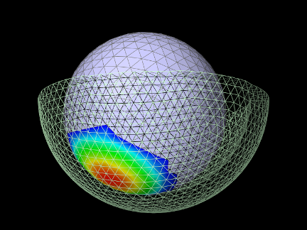
8.7.5 Example: binding EFC properties to fields
It is possible to bind certain EFC material properties to a field, for situations where these properties vary over the surface of the contacting meshes. Properties of LinearElasticContact that can be bound to (scalar) fields include YoungsModulus and thickness, using the methods
Most typically, the properties will be bound to a mesh field (Section 7.3) defined with respect to one of the colliding meshes.
When determining the value of either youngsModulus or thickness within its computeResponse() method, LinearElasticContact checks to see if the property is bound to a field. If it is, the method first checks if the field is a mesh field associated with the meshes of either cpnt0 or cpnt1, and if so, extracts the value using the vertex information of the associated contact point. Otherwise, the value is extracted from the field using the position of cpnt0.
A simple example of binding the thickness property to a field is given by
artisynth.demos.tutorial.VariableElasticContact
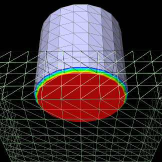
This implements EFC between a beveled cylinder and a plate on which it is resting. The plate is made transparent, allowing the contact pressure to be viewed from below.
|
The model’s code is similar to that for ElasticFoundationContact (Section 8.7.4), except that the collidables are different and the EFC thickness property is bound to a field. The source code for the first part of the build method is shown below:
First, the cylinder and the plate are created as rigid bodies (lines 6-23), with the cylinder defined by a mesh read from the file data/beveledCylinder.obj relative to the demo source directory. The plate is fixed in place and positioned so that it is directly under the cylinder.
Next, the contact method is set to VERTEX_PENETRATION (as
required for EFC), this time by setting it for all collisions in the
collision manager, and a LinearElasticContact is constructed,
with ![]() ,
, ![]() , damping factor
, damping factor ![]() , and thickness
, and thickness ![]() (lines 25-32). Then in lines 34-43, a ScalarMeshField is created
for the cylinder surface mesh, with vertex values set so that the
field defines a thickness value
(lines 25-32). Then in lines 34-43, a ScalarMeshField is created
for the cylinder surface mesh, with vertex values set so that the
field defines a thickness value ![]() that increases with the radial
distance
that increases with the radial
distance ![]() from the cylinder axis according to:
from the cylinder axis according to:
This field is then added to the fields list of the MechModel and the EFC thickness property is bound to it (lines 44-46).
Lastly, a collision behavior is created, with the EFC added to it as a force behavior, and used to enable cylinder/plate collisions (lines 48-53).
It is important that EFC properties are bound to fields before the behavior method setForceBehavior() is called, because that method copies the force behavior and so subsequent field bindings would not be noticed. If for some reason the bindings must be made after the call, they should be applied to the copied force behavior, which can be obtained using getForceBehavior().
To run this example in ArtiSynth, select All demos > tutorial > VariableElasticContact from the Models menu. Running the model will result in contact pressures seen in the left of Figure 8.19, with the pressures decreasing radially in response to the increasing thickness. With no field binding, the pressures are constant across the cylinder bottom (Figure 8.19, right).
![[LOGO]](data:image/png;base64,iVBORw0KGgoAAAANSUhEUgAAAAsAAAAOCAYAAAD5YeaVAAAAAXNSR0IArs4c6QAAAAZiS0dEAP8A/wD/oL2nkwAAAAlwSFlzAAALEwAACxMBAJqcGAAAAAd0SU1FB9wKExQZLWTEaOUAAAAddEVYdENvbW1lbnQAQ3JlYXRlZCB3aXRoIFRoZSBHSU1Q72QlbgAAAdpJREFUKM9tkL+L2nAARz9fPZNCKFapUn8kyI0e4iRHSR1Kb8ng0lJw6FYHFwv2LwhOpcWxTjeUunYqOmqd6hEoRDhtDWdA8ApRYsSUCDHNt5ul13vz4w0vWCgUnnEc975arX6ORqN3VqtVZbfbTQC4uEHANM3jSqXymFI6yWazP2KxWAXAL9zCUa1Wy2tXVxheKA9YNoR8Pt+aTqe4FVVVvz05O6MBhqUIBGk8Hn8HAOVy+T+XLJfLS4ZhTiRJgqIoVBRFIoric47jPnmeB1mW/9rr9ZpSSn3Lsmir1fJZlqWlUonKsvwWwD8ymc/nXwVBeLjf7xEKhdBut9Hr9WgmkyGEkJwsy5eHG5vN5g0AKIoCAEgkEkin0wQAfN9/cXPdheu6P33fBwB4ngcAcByHJpPJl+fn54mD3Gg0NrquXxeLRQAAwzAYj8cwTZPwPH9/sVg8PXweDAauqqr2cDjEer1GJBLBZDJBs9mE4zjwfZ85lAGg2+06hmGgXq+j3+/DsixYlgVN03a9Xu8jgCNCyIegIAgx13Vfd7vdu+FweG8YRkjXdWy329+dTgeSJD3ieZ7RNO0VAXAPwDEAO5VKndi2fWrb9jWl9Esul6PZbDY9Go1OZ7PZ9z/lyuD3OozU2wAAAABJRU5ErkJggg==)