8.4 Implementation
This section describes the technical details of the different ways in which collisions are implemented in ArtiSynth. Knowledge of these details can be useful for choosing collision behavior property settings, understanding elastic foundation contact (Section 8.7.3), and interpreting the information provided by collision responses (Section 8.8.1) and collision rendering (Section 8.5).
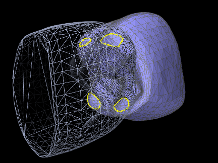
The collision mechanism works by using a collider (described further below) to locate the contact regions where the (triangular) collision meshes of different collidables intersect each other. Figure 8.7 shows four contact regions between two meshes representing human teeth. Information about each contact region is then used to generate contact constraints, according to a contact method, that prevent further collision and resolve any existing interpenetration.
 |
 |
8.4.1 Contact methods
Contact constraints are computed from mesh contact regions using one of two primary contact methods:
8.4.1.1 Contour region
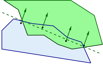
Contact constraints are generated for each contact region by first fitting a plane to the region, and then selecting contact points around its perimeter such that their 2D projection into the plane forms a convex hull (Figure 8.8). A contact constraint is assigned to each contact point, with a constraint direction parallel to the plane normal and a penetration distance given by the maximum interpenetration of the region. Note that the contact points do not necessarily lie on the plane, but they all have the same normal and penetration distance.
This is the default method used between rigid bodies, since it does not depend on mesh resolution, and rigid body contact behavior depends only on the convex hull of the contacting regions. Since the number of contact constraints may exceed the number of degrees of freedom (DOF) of the contacting bodies, the constraints are supplied to the physics solver as unilateral constraints (Section 1.2.3). Using contact region constraints when one of the collidables is an FEM model will result in an error.
8.4.1.2 Vertex penetration
 |
 |
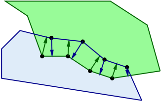
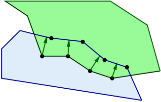
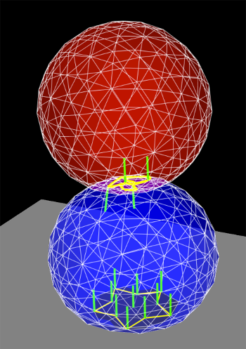
Contacts are created for each mesh vertex that penetrates the other mesh, with a contact normal directed toward the nearest point on the opposing mesh (Figure 8.9). Contact constraints are generated for each contact, with the constraint direction parallel to the normal and the penetration distance equal to the distance to the opposing mesh.
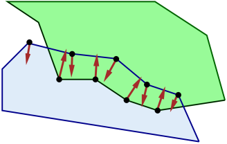
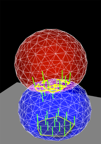
This is the default contact method when one or both of the collidables is an FEM model. Also by default, if only one of the collidables is an FEM model, vertex penetrations are computed only for the FEM collidable; penetrations of the rigid body into the FEM are not considered. Otherwise, if both collidables are FEM models, then vertex penetrations are computed for both bodies, resulting in two-way contact (Figure 8.10).
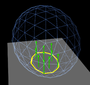
Vertex penetration contact results in contact reaction forces being generated on the mesh vertices that are within or next to the intersection region (Figure 8.9). These appear on vertices of both intersecting meshes, regardless of whether contact points are generated for one or both meshes, since each vertex associated with a contact imparts a reaction force on the vertices of the nearest face on the opposite mesh.
Because FEM models tend to have a large number of DOFs, the default behavior is to supply vertex penetration constraints to the physics solver as bilateral constraints (Section 1.2.3), removing them only between simulation time steps when the contact disappears or a separating force is detected. This results in much faster simulation times, particularly for FEM models, because it does not require solving a linear complementarity problem. However, this also means that using vertex penetration between rigid bodies, or other bodies with a low number of degrees of freedom, will typically result in an overconstrained system that must be handled using one of the techniques described in Section 8.6.
8.4.1.3 Setting the contact method
Contact methods can be specified by the method property in either the collision manager or behavior (Section 8.2.1). The property’s value is an instance of CollisionBehavior.Method, for which the standard settings are:
- CONTOUR_REGION
-
Contact constraints are generated using contour regions, as described in Section 8.4.1.1. Setting this for contact that involves one or more FEM models will result in an error.
- VERTEX_PENETRATION
-
Contact constraints are generated using vertex penetration, as described in Section 8.4.1.2. Setting this for contact between rigid bodies may result in an overconstrained system.
- VERTEX_EDGE_PENETRATION
-
An experimental version of vertex penetration contact that supplements vertex constraints with extra constraints formed from edge-edge contact. Intended for collision meshes with low mesh resolutions and sharp edges. Available only when using the AJL_CONTOUR collider type (Section 8.4.2).
- DEFAULT
-
Selects CONTOUR_REGION when both collidables are rigid bodies and VERTEX_PENETRATION otherwise.
- INACTIVE
-
No constraints are generated. This will result in no collision response.
When vertex penetration contact is employed, the collidables for which penetrations are generated can also be controlled using the vertexPenetrations property, whose value is an instance of CollisionBehavior.VertexPenetrations:
- BOTH_COLLIDABLES
-
Vertex penetrations are computed for both collidables.
- FIRST_COLLIDABLE
-
Vertex penetrations are computed for the first collidable.
- SECOND_COLLIDABLE
-
Vertex penetrations are computed for the second collidable.
- AUTO
-
Vertex penetrations are determined automatically as follows: for both collidables if neither is a rigid body, for the non-rigid collidable if one collidable is a rigid body, and for the first collidable otherwise.
8.4.2 Collider types
The contact regions used by the contact method are generated by a collider, which is specified by the colliderType property in either the collision manager (as the default), or in the collision behavior for a specific pair of collidables. The property’s value is an instance of CollisionManager.ColliderType, which describes the three collider types presently supported:
- TRI_INTERSECTION
-
The original ArtiSynth collider which uses a bounding-box hierarchy to locate all triangle intersections between the two surface meshes. Contact regions are then estimated by grouping the intersection points together, and penetrating vertices are computed separately using point-mesh distance queries based on the bounding-box hierarchy. This latter step requires iterating over all mesh vertices, which may be slow for large meshes. TRI_INTERSECTION can often handle intersections near the edges of an open mesh, but does not support the VERTEX_EDGE_PENETRATION contact method.
- AJL_CONTOUR
-
A bounding-box hierarchy is used to locate all triangle intersections between the two surface meshes, and the intersection points are then connected, using robust geometric predicates, to find the (piecewise linear) intersection contours. The contours are then used to identify the contact regions on each surface mesh, which are in turn used to determine the interpenetrating vertices and contact area. Intersection contours and the contact constraints generated from them are shown in Figure 8.12. AJL_CONTOUR supports the VERTEX_EDGE_PENETRATION contact method, but usually cannot handle intersections near the edges of an open mesh.
- SIGNED_DISTANCE
-
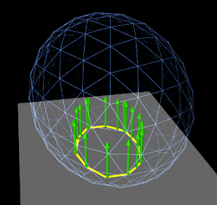
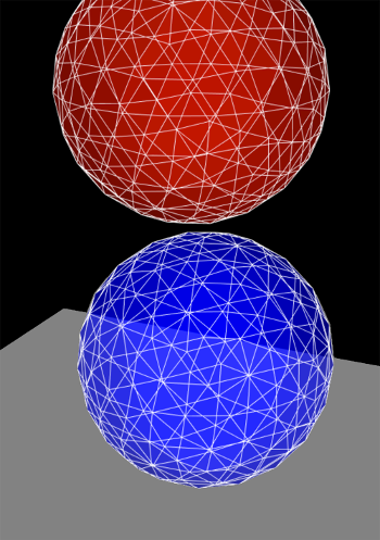
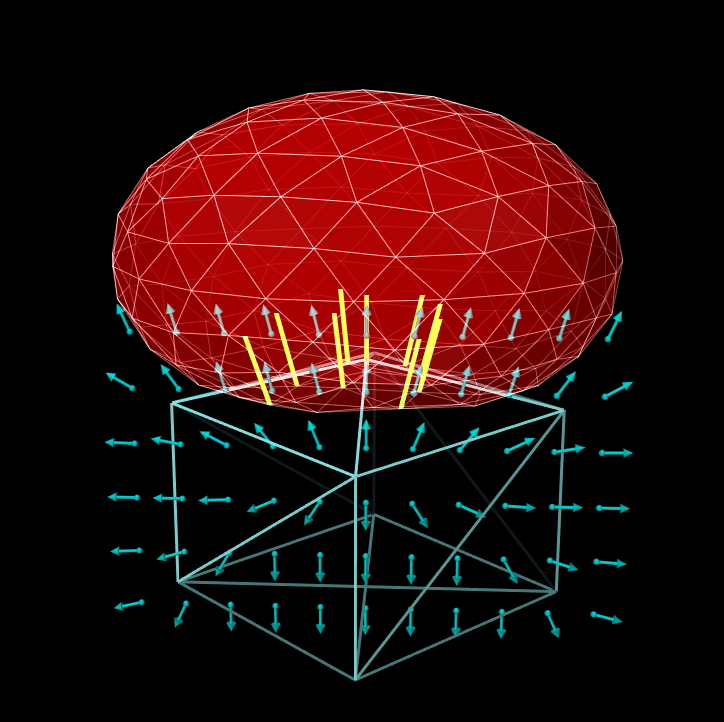
Uses a grid-based signed distance field on one mesh to quickly determine the penetrating vertices of the opposite mesh, along with the penetration distance and normals. This is only available for collidable pairs where at least one of the bodies maintains a signed distance grid which can be obtained using getDistanceGridComp(). Advantages include speed (sometimes an order of magnitude faster than the other colliders) and the fact that the opposite mesh does not have to be triangular or manifold. However, signed distance fields can (at present) only be computed for fixed meshes, and so at least one colliding body must be rigid. The signed distance field also does not yet yield contact region information, and so the contact method is restricted to VERTEX_PENETRATION. Contacts generated from a signed distance field are illustrated in Figure 8.13.
Because the SIGNED_DISTANCE collider type currently supports only the VERTEX_PENETRATION method, its use between rigid bodies, or low DOF deformable bodies, will generally result in an overconstrained system unless measures are taken as described in Section 8.6.
 |
 |
 |
|
|
|
|
8.4.2.1 Collision meshes and signed distance grids
As described in Section 8.3.4, collidable bodies declare the method getCollisionMesh(), which returns a mesh defining the collision surface. This is either used directly, or, for the SIGNED_DISTANCE collider, used to compute a signed distance grid which in turn is used to handle collisions.
For RigidBody objects, the mesh returned by getCollisionMesh() is typically the same as the surface mesh. However, it is possible to change this, by adding additional meshes to the body and modifying the meshes’ isCollidable property (see Section 8.3). The collision mesh is then formed as the sum of all polygonal meshes in the body’s meshes list whose isCollidable property is true.
Collidable bodies also declare the methods hasDistanceGrid() and getDistanceGridComp(). If the former returns true, then the body has a distance grid and the latter returns a DistanceGridComp containing it. A distance grid is a regular 3D grid, with uniformly arranged vertices and cells, that is used to represent a scalar distance field, with distance values stored implicitly at each vertex and interpolated within cells. Distance grids are used by the SIGNED_DISTANCE collider, and by default are generated on-demand, using an automatically chosen resolution and the mesh returned by getCollisionMesh() as the surface against which distances are computed.
When used for collision handling, values within a distance grid are interpolated trilinearly within each cell. This means that the effective collision surface is actually the trilinearly interpolated isosurface corresponding to a distance of 0. This surface will differ somewhat from the original surface returned by getCollisionMesh(), in a manner that depends on the grid resolution. Consequently, when using the SIGNED_DISTANCE collider, it is important to be able to visualize the trilinear isosurface, and possibly modify it by adjusting the grid resolution. The DistanceGridComp returned by getDistanceGridComp() exports properties to facilitate both of these requirements, as described in detail in Section 4.6.
![[LOGO]](data:image/png;base64,iVBORw0KGgoAAAANSUhEUgAAAAsAAAAOCAYAAAD5YeaVAAAAAXNSR0IArs4c6QAAAAZiS0dEAP8A/wD/oL2nkwAAAAlwSFlzAAALEwAACxMBAJqcGAAAAAd0SU1FB9wKExQZLWTEaOUAAAAddEVYdENvbW1lbnQAQ3JlYXRlZCB3aXRoIFRoZSBHSU1Q72QlbgAAAdpJREFUKM9tkL+L2nAARz9fPZNCKFapUn8kyI0e4iRHSR1Kb8ng0lJw6FYHFwv2LwhOpcWxTjeUunYqOmqd6hEoRDhtDWdA8ApRYsSUCDHNt5ul13vz4w0vWCgUnnEc975arX6ORqN3VqtVZbfbTQC4uEHANM3jSqXymFI6yWazP2KxWAXAL9zCUa1Wy2tXVxheKA9YNoR8Pt+aTqe4FVVVvz05O6MBhqUIBGk8Hn8HAOVy+T+XLJfLS4ZhTiRJgqIoVBRFIoric47jPnmeB1mW/9rr9ZpSSn3Lsmir1fJZlqWlUonKsvwWwD8ymc/nXwVBeLjf7xEKhdBut9Hr9WgmkyGEkJwsy5eHG5vN5g0AKIoCAEgkEkin0wQAfN9/cXPdheu6P33fBwB4ngcAcByHJpPJl+fn54mD3Gg0NrquXxeLRQAAwzAYj8cwTZPwPH9/sVg8PXweDAauqqr2cDjEer1GJBLBZDJBs9mE4zjwfZ85lAGg2+06hmGgXq+j3+/DsixYlgVN03a9Xu8jgCNCyIegIAgx13Vfd7vdu+FweG8YRkjXdWy329+dTgeSJD3ieZ7RNO0VAXAPwDEAO5VKndi2fWrb9jWl9Esul6PZbDY9Go1OZ7PZ9z/lyuD3OozU2wAAAABJRU5ErkJggg==)