8.3 Collision meshes and compound collidables
Contact between collidable bodies is determined by finding intersections between their collision meshes. Collision meshes must be instances of PolygonalMesh, and must also be triangular, manifold, oriented, and non-self-intersecting (at least in the region of contact). The oriented requirement helps the collision detector differentiate inside from outside. Collision meshes should also be closed, if possible, although collision may sometimes work with the open meshes (such as those that arise with shell elements) under conditions described in Section 8.1.4. Collision meshes do not need to be connected; a collision mesh may be composed of separate parts.
Commonly, a collidable body has a single collision mesh which is the same as its surface mesh. However, some collidables, such as rigid bodies and FEM models, allow an application to specify a collidable mesh that is different from its surface mesh. This can be useful in situations such as the following:
-
•
Collisions should be enabled for only part of a collidable, perhaps because other parts are in contact due to joints or other types of attachment.
-
•
The collision mesh requires a different resolution than the surface mesh, possibly for computational reasons.
-
•
The collision mesh requires a different geometry, such as in situations where the collidable’s physical surface is sufficiently thin that it may otherwise pass through other collidables undetected (Section 8.9.2).
For a rigid body, the collision mesh is returned by its getCollisionMesh() method (see Section 8.3.4). By default, this is the same as the surface mesh returned by getSurfaceMesh(). However, the collision mesh can be changed by adding one (or more) additional mesh components to the meshes component list and setting its isCollidable property to true, usually while also setting isCollidable to false for the surface mesh (Section 3.2.9). The collision mesh returned by getCollisionMesh() is then formed from the union of all rigid body meshes for which isCollidable is true.
The sum operation used to create the RigidBody collision mesh uses addMesh(), which simply adds all vertices and faces together. While the result works correctly for collisions, it does not represent a proper CSG union operation (such as that described in Section 2.5.7) and may contain interpenetrating and overlapping features. Care should be taken to ensure that the resulting mesh is not self-intersecting in the regions that will be exposed to contact.
For FEM models, the mechanism is a little different, as discussed below in Section 8.3.2. An FEM model can have multiple collision meshes, depending on the setting of the collidable property of each of its mesh components. The ability to have multiple collision meshes permits self-collision intersection of the FEM model with itself.
8.3.1 Example: redefining a rigid body collision mesh
A model illustrating how to redefine the collision mesh for a rigid body is defined in
artisynth.demos.tutorial.JointedBallCollide
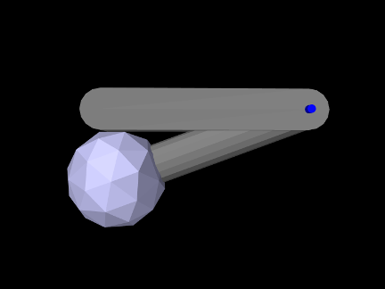
Like JointedCollide in Section 8.1.3, this model is simply a subclass of RigidBodyJoint that overrides the build() method, adding a ball to the tip of bodyA to enable it to collide with bodyB:
The superclass build() method called at line 3 creates everything contained in RigidBodyJoint. The remaining code then alters that model: A ball mesh is created, translated to the tip of bodyA, added as an additional mesh (Section 3.2.9), and set to render as blue-gray (lines 5-10). Next, collisions are disabled for bodyA’s main surface mesh by setting its isCollidable property to false (line 13); this will ensure that the collision mesh associated with bodyA will consist solely of the ball mesh, which is necessary because the surface mesh is permanently in contact with bodyB. Lastly, collisions are enabled between bodyA and bodyB (line 15).
To run this example in ArtiSynth, select All demos > tutorial > JointedBallCollide from the Models menu. Running the model will cause bodyA to fall, pivot about the hinge joint, and collide with bodyB (Figure 8.3).
8.3.2 Compound collidables and self-collision
An FEM model is an example of a compound collidable, which may contain subcollidable descendant components which are also collidable. Compound collidables are identified by having their isCompound() method return true. For an FEM model, the subcollidables are the mesh components in its meshes list. A non-compound collidable which is not a subcollidable of some other (compound) collidable is called solitary. If A is a subcollidable of a compound collidable C, then C is an ancestor collidable of A.
Subcollidables do not need to be immediate child components of the compound collidable; they need only be descendants.
One of the main purposes of compound collidables is to enable self-collisions. While ArtiSynth does not currently support the detection of self-collisions within a single mesh, self-collision can be implemented within a compound collidable C by detecting collisions among the (separate) meshes of its subcollidables.
Compound collidables and their subcollidables are assumed to be deformable; otherwise, subcollision would not be possible.
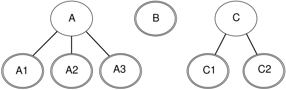
In general, an ArtiSynth model will contain a number of collidable components, some of which are compound (Figure 8.4). The non-compound collidables, including both solitary collidables and leaf nodes of a compound collidable’s tree, are also instances of the subinterface CollidableBody, which provide the collision meshes, along with other information used to compute the collision response (Section 8.3.4).
Actual collisions happen only between CollidableBodys; compound collidables are used only for determining grouping and specifying collision behaviors. The rules for determining whether two collidable bodies A and B will actually collide are as follows:
-
1.
Internal (self) collisions: If A and B are both subcollidables of some compound collidable C, then A and B will collide if (a) both their collidable properties are set to either ALL or INTERNAL, and (b) an explicit collision behavior is set between A and B, or self-collision is enabled for C (as described below).
-
2.
External collisions: Otherwise, if A and B are either solitary or subcollidables of different compound collidables, then they will collide if (a) both their collidable properties are set to either ALL or EXTERNAL, and (b) a specific or default collision behavior is set between them or their collidable ancestors.
As mentioned above, the subcollidables of an FEM are its mesh components (Section 6.3), each of which is a collidable implemented by FemMeshComp. When a mesh component is added to an FEM model, using either addMeshComp() or one of the addMesh() methods, its collidable property is automatically set to INTERNAL, so if a different setting is required, this must be specified after the component has been added to the model.
Subject to the above conditions, self-collision can be enabled for a specific compound collidable C by calling the setCollisionBehavior() methods with collidable0 set to C and collidable1 set to either C or Collidable.SELF, as in for example:
It can also be enabled, by default, for all compound collidables by calling one of the setDefaultCollisionBehavior() methods with collidable0 set to Collidable.DEFORMABLE and collidable1 set to Collidable.SELF, e.g.:
For an example of how collision interactions can be set, refer to Figure 8.4, assume that components A, B and C are deformable, and that the collidable property for all collidables is set to ALL except for A3, where it is set to EXTERNAL (implying that A3 cannot self-collide with A1 and A2). Then if mech is the MechModel containing the collidables, the call
will enable collisions between A1, A2, and A3 and each of B, C1, and C2, and between B and C1 and C2, but not among A1, A2, and A3 or C1 and C2. The subsequent calls
will enable self-collision between A1 and A2 and C1 and C2 with zero friction, and disable collision between B and A3. Finally, the calls
will enable collision between A3 and each of C1 and C2 with friction 0.3, and disable all self-collisions among A1, A2 and A3.
8.3.3 Example: FEM model with self-collision
 |
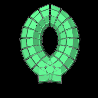 |
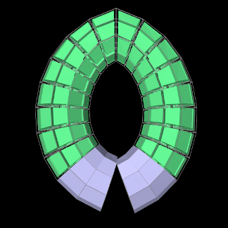
A model illustrating self-collision for an FEM model is defined in
artisynth.demos.tutorial.FemSelfCollide
It creates a simple FEM based on a partial torus that self intersects when it falls under gravity. Internal surface meshes are added to the left and right ends of the model to prevent interpenetration. The code for the build() method is listed below:
The model creates an FEM model based on an open torus, using a factory
method in FemFactory, and
rotates it so that the gap is located at the bottom (lines 7-18). The
torus is then anchored by fixing the nodes located at the top-center
(lines 20-25). Next, mesh components are created to enforce
self-collision at the left and right gap end points (lines 27-47).
First, a FemMeshComp is created
(Section 6.3), and then its createVolumetricSurface() method is used to create a local surface
mesh wrapping the elements specified in elems. When selecting
the elements, we use the convenient fact that for this particular FEM
model, the elements near the left and right ends have numbers in the
ranges ![]() and
and ![]() , respectively.
, respectively.
Once the submeshes have been added to the FEM model, we create a collision behavior and use it to enable self-collisions (lines 49-55). An explicit behavior is created so that we can enable the VERTEX_EDGE_PENETRATION contact method (Section 8.4.1), because the meshes are coarse and the additional edge-edge collisions will improve behavior; this method also requires the AJL_CONTOUR collider type. While self-collision is enabled by calling
it could also have been enabled by calling
Note that there is no need to set the collidable property of the collision meshes since it is set to INTERNAL by default when they are added to the FEM model.
Render properties are set at lines 57-64, with the torus rendered as light green and the collision meshes as blue-gray. The torus is drawn using its element widgets instead of its surface mesh, to prevent the latter from obscuring the collision meshes.
To run this example in ArtiSynth, select All demos > tutorial > FemSelfCollide from the Models menu. Running the model will cause the FEM model to self-collide as shown in Figure 8.5.
8.3.4 Collidable bodies
As mentioned in Section 8.3.2, non-compound collidables, including both solitary collidables and leaf nodes of a compound collidable’s tree, are also instances of CollidableBody, which provide the actual collision meshes and other information used to compute the collision response. This is done using various methods, including:
-
•
PolygonalMesh getCollisionMesh()
Returns the actual surface mesh to be used for computing collisions.
-
•
boolean hasDistanceGrid()
If this method returns true, the body also maintains a signed distance grid for the mesh, which can be used by the collider type SIGNED_DISTANCE (Section 8.4.1).
-
•
DistanceGridComp getDistanceGridComp()
If hasDistanceGrid() returns true, this method returns the distance grid.
-
•
double getMass()
Returns the mass of this body (or a suitable estimate), for use in automatically computing certain collision parameters.
-
•
int getCollidableIndex()
Returns the index of this collidable body within the set of all CollidableBodys in the MechModel. The index is determined by the body’s depth-first ordering within the model component hierarchy. For components within the same component list, this ordering will be determined by the order in which the components are added in the model’s build() method.
8.3.5 Nested MechModels
It is possible in ArtiSynth for one MechModel to contain other nested MechModels within its component hierarchy. This raises the question of how collisions within the nested models are controlled. The general rule for this is the following:
The collision behavior for two collidables colA and colB is determined by whatever behavior (either default or override) is specified by the lowest MechModel in the component hierarchy that contains both colA and colB.
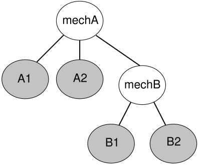
For example, consider Figure 8.6 where we have a MechModel (mechB) containing collidables B1 and B2, nested within another MechModel (mechA) containing collidables A1 and A2. Then consider the following code fragment:
The first line enables default collisions within mechB (with
![]() ), controlling the interaction between B1 and B2.
However, collisions are still disabled within mechA, meaning
A1 and A2 will not collide either with each other or with
B1 or B2. The second line enables collisions between B1 and any other body within mechA (i.e., A1 and
A2), while the third line disables collisions between B1
and A1. Finally, the fourth line results in an error, since
B1 and B2 are both contained within mechB and so
their collision behavior cannot be controlled from mechA.
), controlling the interaction between B1 and B2.
However, collisions are still disabled within mechA, meaning
A1 and A2 will not collide either with each other or with
B1 or B2. The second line enables collisions between B1 and any other body within mechA (i.e., A1 and
A2), while the third line disables collisions between B1
and A1. Finally, the fourth line results in an error, since
B1 and B2 are both contained within mechB and so
their collision behavior cannot be controlled from mechA.
While it is not legal to specify a specific behavior for collidables contained in a MechModel from a higher level MechModel, it is legal to create collision response components for the same pair within both models. So the following code fragment would be allowed and would create response components in both mechA and mechB:
![[LOGO]](data:image/png;base64,iVBORw0KGgoAAAANSUhEUgAAAAsAAAAOCAYAAAD5YeaVAAAAAXNSR0IArs4c6QAAAAZiS0dEAP8A/wD/oL2nkwAAAAlwSFlzAAALEwAACxMBAJqcGAAAAAd0SU1FB9wKExQZLWTEaOUAAAAddEVYdENvbW1lbnQAQ3JlYXRlZCB3aXRoIFRoZSBHSU1Q72QlbgAAAdpJREFUKM9tkL+L2nAARz9fPZNCKFapUn8kyI0e4iRHSR1Kb8ng0lJw6FYHFwv2LwhOpcWxTjeUunYqOmqd6hEoRDhtDWdA8ApRYsSUCDHNt5ul13vz4w0vWCgUnnEc975arX6ORqN3VqtVZbfbTQC4uEHANM3jSqXymFI6yWazP2KxWAXAL9zCUa1Wy2tXVxheKA9YNoR8Pt+aTqe4FVVVvz05O6MBhqUIBGk8Hn8HAOVy+T+XLJfLS4ZhTiRJgqIoVBRFIoric47jPnmeB1mW/9rr9ZpSSn3Lsmir1fJZlqWlUonKsvwWwD8ymc/nXwVBeLjf7xEKhdBut9Hr9WgmkyGEkJwsy5eHG5vN5g0AKIoCAEgkEkin0wQAfN9/cXPdheu6P33fBwB4ngcAcByHJpPJl+fn54mD3Gg0NrquXxeLRQAAwzAYj8cwTZPwPH9/sVg8PXweDAauqqr2cDjEer1GJBLBZDJBs9mE4zjwfZ85lAGg2+06hmGgXq+j3+/DsixYlgVN03a9Xu8jgCNCyIegIAgx13Vfd7vdu+FweG8YRkjXdWy329+dTgeSJD3ieZ7RNO0VAXAPwDEAO5VKndi2fWrb9jWl9Esul6PZbDY9Go1OZ7PZ9z/lyuD3OozU2wAAAABJRU5ErkJggg==)