3.2 Rigid bodies
Rigid bodies are implemented in ArtiSynth by the class RigidBody, which is a dynamic component containing a six-dimensional position and orientation state, a corresponding velocity state, an inertia, and an optional surface mesh.
A rigid body is associated with its own 3D spatial coordinate frame, and is a subclass of the more general Frame component. The combined position and orientation of this frame with respect to world coordinates defines the body’s pose, and the associated 6 degrees of freedom describe its “position” state.
3.2.1 Frame markers
ArtiSynth makes extensive use of markers, which are (massless) points attached to dynamic components in the model. Markers are used for graphical display, implementing attachments, and transmitting forces back onto the underlying dynamic components.
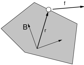
Frame markers are markers that can be attached to a Frame (which includes RigidBody as a subclass), as illustrated in Figure 3.2. They are frequently used to provide the anchor points for attaching springs and, more generally, applying forces to the body.
Frame markers are implemented by the class FrameMarker, which is a subclass of Point. The methods
| Point3d getLocation () | |
| void setLocation (Point3d r) |
get and set the marker’s location ![]() with respect to the frame’s
coordinate system. When a 3D force
with respect to the frame’s
coordinate system. When a 3D force ![]() is applied to the marker, it
generates a spatial force
is applied to the marker, it
generates a spatial force ![]() (Section
A.5) on the frame given by
(Section
A.5) on the frame given by
| (3.0) |
Frame markers can be created using a variety of constructors, including
| FrameMarker () | |
| FrameMarker (String name) | |
| FrameMarker (Frame frame, Point3d loc) |
where FrameMarker() creates an empty marker, FrameMarker(name) creates an empty marker with a name, and FrameMarker(frame,loc) creates an unnamed marker attached to frame at the location loc with respect to the frame’s coordinates. A marker’s frame can also be queried and set with the methods
| void setFrame (Frame frame) | |
| Frame getFrame () |
Once created, a frame marker must be added to the MechModel. This can be done by adding it to the MechModel’s frameMarkers container, which is managed using the following MechModel methods:
| void addFrameMarker (FrameMarker m) |
Adds marker m to the container. |
| void addFrameMarker (FrameMarker m, Frame frame, Point3d loc) |
Adds m and sets its frame and location. |
| boolean removeFrameMarker (FrameMarker m) |
Removes marker m from the container. |
| void clearFrameMarkers() |
Removes all markers. |
| PointList<FrameMarker> frameMarkers() |
Returns the frameMarkers container. |
MechModel also supplies convenience methods to create a marker, attach it to a frame, and add it to the model:
| FrameMarker addFrameMarker (Frame frame, Point3d loc) |
Creates a marker at a frame-relative location. |
| FrameMarker addFrameMarkerWorld (Frame frame, Point3d locw) |
Creates a marker at a world location. |
Both methods return the created marker. The first, addFrameMarker(frame,loc), places it at the location loc with respect to the frame, while addFrameMarkerWorld(frame,pos) places it at pos with respect to world coordinates.
Alternatively, frame markers can also be added directly to the frame or rigid body to which they are attached. Each frame contains a markers container subcomponent, and markers can be added to this using the following Frame methods:
| void addMarker (FrameMarker mkr) |
Adds an existing marker to the frame. |
| FrameMarker addMarker (Point3d loc) |
Creates a marker at location loc with respect to frame coords. |
| FrameMarker addMarkerWorld (Point3d pos) |
Creates a marker at position pos given in world coordinates. |
A frame’s markers container can be accessed, and markers can be removed, using
| PointList<? extends FrameMarker> getMarkers () |
Returns the frame’s markers list. |
| boolean removeMarker (FrameMarker mkr) |
Removes a marker from the markers list. |
| void clearMarkers () |
Removes all markers from the markers list. |
3.2.2 Example: a simple rigid body-spring model
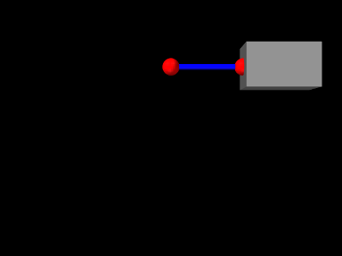
A simple rigid body-spring model is defined in
artisynth.demos.tutorial.RigidBodySpring
This differs from ParticleSpring only in the build() method, which is listed below:
The differences from ParticleSpring begin
at line 9. Instead of creating a second particle, a rigid body is
created using the factory method
RigidBody.createBox(), which
takes x, y, z widths and a (uniform) density and creates a box-shaped
rigid body complete with surface mesh and appropriate mass and
inertia. As the box is initially centered at the origin, moving it
elsewhere requires setting the body’s pose, which is done using setPose(). The RigidTransform3d passed to setPose() is
created using a three-argument constructor that generates a
translation-only transform. Next, starting at line 14, a FrameMarker is created for a location ![]() relative to the
rigid body, and attached to the body using its setFrame()
method.
relative to the
rigid body, and attached to the body using its setFrame()
method.
The remainder of build() is the same as for ParticleSpring, except that the spring is attached to the frame marker instead of a second particle.
3.2.3 Creating rigid bodies
As illustrated above, rigid bodies can be created using factory methods supplied by RigidBody. Some of these include:
The bodies do not need to be named; if no name is desired, then name can be specified as null.
In addition, there are also factory methods for creating a rigid body directly from a mesh:
These take either a polygonal mesh (Section 2.5), or a file name from which a mesh is read, and use it as the body’s surface mesh and then compute the mass and inertia properties from the specified (uniform) density.
When a body is created directly from a surface mesh, its center of mass will typically not be coincident with the origin of its coordinate frame. Section 3.2.6 discusses the implications of this and how to correct it.
Alternatively, one can create a rigid body directly from a constructor, and then set the mesh and inertia properties explicitly:
3.2.4 Pose and velocity
A body’s pose can be set and queried using the methods
These use a RigidTransform3d (Section
2.2) to describe the pose. Body poses are
described in world coordinates and specify the transform from body to
world coordinates. In particular, the pose for a body A specifies
the rigid transform ![]() .
.
Rigid bodies also expose the translational and rotational components of their pose via the properties position and orientation, which can be queried and set independently using the methods
The velocity of a rigid body is described using a Twist (Section 2.4), which contains both the translational and rotational velocities. The following methods set and query the spatial velocity as described with respect to world coordinates:
During simulation, unless a rigid body has been set to be parametric (Section 1.2.4), its pose and velocity are updated in response to forces, so setting the pose or velocity generally makes sense only for setting initial conditions. On the other hand, if a rigid body is parametric, then it is possible to control its pose during the simulation, but in that case it is better to set its target pose and/or target velocity, as described in Section 5.3.1.
3.2.5 Inertia and the surface mesh
The “mass” of a rigid body is described by its spatial inertia,
which is a ![]() matrix relating its spatial velocity to its
spatial momentum (Section A.6). Within
ArtiSynth, spatial inertia is described by a
SpatialInertia object, which
specifies its mass, center of mass (with respect to body coordinates),
and rotational inertia (with respect to the center of mass).
matrix relating its spatial velocity to its
spatial momentum (Section A.6). Within
ArtiSynth, spatial inertia is described by a
SpatialInertia object, which
specifies its mass, center of mass (with respect to body coordinates),
and rotational inertia (with respect to the center of mass).
Most rigid bodies are also associated with a polygonal surface mesh, which can be set and queried using the methods
The second method takes an optional fileName argument that can be set to the name of a file from which the mesh was read. Then if the model itself is saved to a file, the model file will specify the mesh using the file name instead of explicit vertex and face information, which can reduce the model file size considerably.
Rigid bodies can also have more than one mesh, as described in Section 3.2.9.
The inertia of a rigid body can be explicitly set using a variety of methods including
and can be queried using
In practice, it is often more convenient to simply specify a mass or a density, and then use the geometry of the surface mesh (and possibly other meshes, Section 3.2.9) to compute the remaining inertial values. How a rigid body’s inertia is computed is determined by its inertiaMethod property, which can be one of:
- EXPLICIT
-
Inertia is set explicitly.
- MASS
-
Inertia is determined implicitly from the mesh geometry and the body’s mass.
- DENSITY
-
Inertia is determined implicitly from the mesh geometry and the body’s density (which is multiplied by the mesh volume(s) to determine a mass).
When using DENSITY to determine the inertia, it is generally assumed that the contributing meshes are both polygonal and closed. Meshes which are either open or non-polygonal generally do not have a well-defined volume which can be multiplied by the density to determine the mass.
The inertiaMethod property can be set and queried using
and its default value is DENSITY. Explicitly setting the inertia using one of the setInertia() methods described above will set inertiaMethod to EXPLICIT. The method
will (re)compute the inertia using the mesh geometry and a density value and set inertiaMethod to DENSITY, and the method
will (re)compute the inertia using the mesh geometry and a mass value and set inertiaMethod to MASS.
Finally, the (assumed uniform) density of the body can be queried using
There are some subtleties involved in determining the inertia using either the DENSITY or MASS methods when the rigid body contains more than one mesh. Details are given in Section 3.2.9.
3.2.6 Coordinate frames and the center of mass
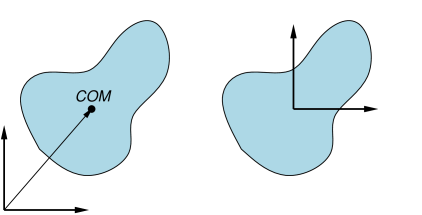
It is important to note that the origin of a body’s coordinate frame will not necessarily coincide with its center of mass (COM), and in fact the frame origin does not even have to lie inside the body’s surface (Figure 3.4). This typically occurs when a body’s inertia is computed directly from its surface mesh (or meshes), as described in Section 3.2.5.
Having the COM differ from the frame origin may lead to some undesired
effects. For instance, since the body’s spatial velocity is defined
with respect to the frame origin and not the COM, if the two are not
coincident, then a purely angular body velocity will cause the COM to
translate. The body’s spatial inertia also becomes more complicated,
with non-zero ![]() blocks in the lower left and upper right
(Section A.6), which can have a small effect on
computational accuracy. Finally, manipulating a body’s pose in the
ArtiSynth UI (as described in the section “Model Manipulation” in
the
ArtiSynth User Interface Guide) can
also be more cumbersome if the origin is located far from the COM.
blocks in the lower left and upper right
(Section A.6), which can have a small effect on
computational accuracy. Finally, manipulating a body’s pose in the
ArtiSynth UI (as described in the section “Model Manipulation” in
the
ArtiSynth User Interface Guide) can
also be more cumbersome if the origin is located far from the COM.
There are several ways to ensure that the COM and frame origin are coincident. The most direct is to call the method centerPoseOnCenterOfMass() after the body has been created:
This will shift the body’s frame to be coincident with the COM, while at the same time translating its mesh vertices in the opposite direction so that its mesh (or meshes) don’t move with respect to world coordinates. The spatial inertia is updated as well.
Alternatively, if the body is being created from a single mesh, one may transform that mesh to be centered on its COM before it is used to define the body. This can be done using the PolygonalMesh method translateToCenterOfVolume(), which centers a mesh’s vertices on its COM (assuming a uniform density):
3.2.7 Damping parameters
As with particles, it is possible to set damping parameters for rigid bodies. Damping can be specified in two different ways:
-
1.
Translational/rotational damping which is proportional to a body’s translational and rotational velocity;
-
2.
Inertial damping, which is proportional to a body’s spatial inertia multiplied by its spatial velocity.
Translational/rotational damping is controlled by the MechModel properties frameDamping and rotaryDamping, and generates a spatial force centered on each rigid body’s coordinate frame given by
| (3.0) |
where ![]() and
and ![]() are the frameDamping and rotaryDamping values, and
are the frameDamping and rotaryDamping values, and ![]() and
and ![]() are the translational
and angular velocity of the body’s coordinate frame. The damping
parameters can be set and queried using the MechModel methods
are the translational
and angular velocity of the body’s coordinate frame. The damping
parameters can be set and queried using the MechModel methods
These damping parameters can also be set for individual bodies using their own (inherited) frameDamping and rotaryDamping properties.
For models involving rigid bodies, it is often necessary to set rotaryDamping to a non-zero value because frameDamping will provide no damping at all when a rigid body is simply rotating about its coordinate frame origin.
Inertial damping is controlled by the MechModel property inertialDamping, and generates a spatial force centered on a rigid body’s coordinate frame given by
| (3.1) |
where ![]() is the inertialDamping,
is the inertialDamping, ![]() is the body’s
is the body’s ![]() spatial inertia matrix (Section A.6), and
spatial inertia matrix (Section A.6), and
![]() is the body’s spatial velocity. The inertial damping property
can be set and queried using the MechModel methods
is the body’s spatial velocity. The inertial damping property
can be set and queried using the MechModel methods
This parameter can also be set for individual bodies using their own (inherited) inertialDamping property.
Inertial damping offers two advantages over translational/rotational damping:
- 1.
It is independent of the location of the body’s coordinate frame with respect to its center of mass;
- 2.
There is no need to adjust two different translational and rotational parameters or to consider their relative sizes, as these considerations are contained within the spatial inertia itself.
3.2.8 Rendering rigid bodies
A rigid body is rendered in ArtiSynth by drawing its mesh (or meshes, Section 3.2.9) and/or coordinate frame.
Meshes are drawn using the face rendering properties described in more detail in Section 4.3. The most commonly used of these are:
-
•
faceColor: A value of type java.awt.Color giving the color of mesh faces. The default value is GRAY.
-
•
shading: A value of type Renderer.Shading indicating how the mesh should be shaded, with the options being FLAT, SMOOTH, METAL, and NONE. The default value is FLAT.
-
•
alpha: A double value between 0 and 1 indicating transparency, with transparency increasing as value decreases from 1. The default value is 1.
-
•
faceStyle: A value of type Renderer.FaceStyle indicating which face sides should be drawn, with the options being FRONT, BACK, FRONT_AND_BACK, and NONE. The default value is FRONT.
-
•
drawEdges: A boolean indicating whether the mesh edges should also be drawn, using either the edgeColor rendering property, or the lineColor property if edgeColor is not set. The default value is false.
-
•
edgeWidth: An integer giving the width of the mesh edges in pixels.
These properties, and others, can be set either interactively in the GUI, or in code. To set the render properties in the GUI, select the rigid body or its mesh component, and then right click the mouse and choose Edit render props .... More details are given in the section “Render properties” in the ArtiSynth User Interface Guide.
 |
 |
 |
Properties can also be set in code, usually during the build() method. Typically this is done using a static method of the RenderProps class that has the form
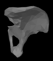
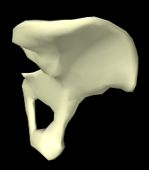
where XXX is the property name, comp is the component for which the property should be set, and value is the desired value. Some examples are shown in Figure 3.5 for a rigid body hip representation with a fairly coarse mesh. The left image shows the default rendering, using a gray color and flat shading. The center image shows a lighter color and smooth shading, which could be set by the following code fragment:
Finally, the right image shows the body rendered as a wire frame, which can be done by setting faceStyle to NONE and drawEdges to true:
Render properties can also be set in higher level model components, from which their values will be inherited by lower level components that have not explicitly set their own values. For example, setting the faceColor render property in the MechModel will automatically set the face color for all subcomponents which have not explicitly set faceColor. More details on render properties are given in Section 4.3.
 |
 |
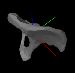
In addition to mesh rendering, it is often useful to draw a rigid
body’s coordinate frame, which can be done using its axisLength
and axisDrawStyle properties. Setting axisLength to a
positive value will cause the body’s three coordinate axes to be
drawn, with the indicated length, with the ![]() ,
, ![]() and
and ![]() axes
colored red, green, and blue, respectively. The axisDrawStyle
property controls how the axes are rendered (Figure
3.6). It has the type
Renderer.AxisDrawStyle, and can
be set to the following values:
axes
colored red, green, and blue, respectively. The axisDrawStyle
property controls how the axes are rendered (Figure
3.6). It has the type
Renderer.AxisDrawStyle, and can
be set to the following values:
- OFF
-
Axes are not rendered.
- LINE
-
Axes are rendered as simple red-green-blue lines, with a width given by the joint’s lineWidth rendering property.
- ARROW
-
Axes are rendered as solid red-green-blue arrows.
As with the rendering properties, the axisLength and axisDrawStyle properties can be managed either interactively in the GUI (by selecting the body, right clicking and choosing Edit properties ...), or in code, using the following methods:
3.2.9 Multiple meshes
A RigidBody may contain multiple meshes, which can be useful for various reasons:
-
•
It may be desirable to use different meshes for collision detection, inertia computation, and visual presentation;
-
•
Different render properties can be set for different mesh components, allowing the body to be rendered in a more versatile way;
-
•
Different mesh components can be selected individually.
Each rigid body mesh is encapsulated inside a RigidMeshComp component, which is in turn stored in a subcomponent list called meshes. Meshes do not need to be instances of PolygonalMesh; instead, they can be any instance of MeshBase, including PointMesh and PolylineMesh.
The default surface mesh, returned by getSurfaceMesh(), is also stored inside a RigidMeshComp in the meshes list. By default, the surface mesh is the first mesh in the list, but is otherwise defined to be the first mesh in meshes which is also an instance of PolygonalMesh. The RigidMeshComp containing the surface mesh can be obtained using the method getSurfaceMeshComp().
A RigidMeshComp contains a number of properties that control how the mesh is displayed and interacts with its rigid body:
- renderProps
-
Render properties controlling how the mesh is rendered (see Section 4.3).
- hasMass
-
A boolean, which if true means that the mesh will contribute to the body’s inertia when the inertiaMethod is either MASS or DENSITY. The default value is true.
- massDistribution
-
An enumerated type defined by MassDistribution which specifies how the mesh’s inertia contribution is determined for a given mass. VOLUME, AREA, LENGTH, and POINT indicate, respectively, that the mass is distributed evenly over the mesh’s volume, area (faces), length (edges), or points. The default value is determined by the mesh type: VOLUME for a closed PolygonalMesh, AREA for an open PolygonalMesh, LENGTH for a PolylineMesh, and POINT for a PointMesh. Applications can specify an alternate value providing the mesh has the features to support it. Specifying DEFAULT will restore the default value.
- isCollidable
-
- volume
-
A double whose value is the volume of the mesh. If the mesh is a PolygonalMesh, this is the value returned by its computeVolume() method. Otherwise, the volume is 0, unless setVolume(vol) is used to explicitly set a non-zero volume value.
- mass
-
A double whose default value is the product of the density and volume properties. Otherwise, if mass has been explicitly set using setMass(mass), the value is the explicit mass.
- density
-
A double whose default value is the rigid body’s density. Otherwise, if density has been explicitly set using setDensity(density), the value is the explicit density, or if mass has been explicitly set using setMass(mass), the value is the explicit mass divided by volume.
Note that by default, the density of a RigidMeshComp is simply the density setting for the rigid body, and the mass is this times the volume. However, it is possible to set either an explicit mass or a density value that will override this. (Also, explicitly setting a mass will unset any explicit density, and explicitly setting the density will unset any explicit mass.)
When the inertiaMethod of the rigid body is either MASS or
DENSITY, then its inertia is computed from the sum of all the
inertias ![]() of the component meshes
of the component meshes ![]() for which hasMass is
true. Each
for which hasMass is
true. Each ![]() is computed by the mesh’s
createInertia(mass,massDistribution) method,
using the mass and massDistribution properties of
its RigidMeshComp.
is computed by the mesh’s
createInertia(mass,massDistribution) method,
using the mass and massDistribution properties of
its RigidMeshComp.
When forming the body inertia from the inertia components of individual meshes, no attempt is made to account for mesh overlap. If this is important, the meshes themselves should be modified in advance so that they do not overlap, perhaps by using the CSG primitives described in Section 2.5.7.
Instances of RigidMeshComp can be created directly, using constructions such as
or
after which they can be added or removed from the meshes list using the methods
It is also possible to add meshes directly to the meshes list, using the methods
each of which creates a RigidMeshComp, adds it to the mesh list, and returns it. The second method also specifies the values of the hasMass and collidable properties (both of which are true by default).
3.2.10 Example: a composite rigid body
An example of constructing a rigid body from multiple meshes is defined in
artisynth.demos.tutorial.RigidCompositeBody
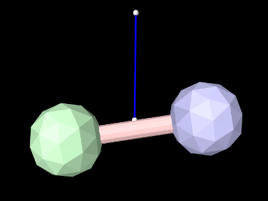
This uses three meshes to construct a rigid body whose shape resembles a dumbbell. The code, with the include files omitted, is listed below:
As in the previous examples, the build() method starts by creating a MechModel (lines 6-7). Three different meshes (two balls and an axis) are then constructed at lines 10-15, using MeshFactory methods (Section 2.5) and transforming each result to an appropriate position/orientation with respect to the body’s coordinate frame.
The body itself is constructed at lines 18-24. Its default density is set to 10, and its frame damping (Section 3.2.7) is also set to 10 (the previous rigid body example in Section 3.2.2 relied on spring damping to dissipate energy). The meshes are added using addMesh(), which allocates and returns a RigidMeshComp. For the ball meshes, these are saved in bcomp1 and bcomp2 and used later to adjust density and/or render properties.
Lines 27-34 create a simple linear spring, connected to a fixed point p0 and a marker mkr. The marker is created and attached to the body by the MechModel method addFrameMarkerWorld(), which places the marker at a known position in world coordinates. The spring is created using an AxialSpring constructor that accepts a name, along with stiffness, damping, and rest length parameters to specify a LinearAxialMaterial.
At line 37, bcomp1 is used to set the density of ball1 to 8. Since this is less than the default body density, the inertia component of ball1 will be lighter than that of ball2. Finally, render properties are set at lines 41-45. This includes setting the default face colors for the body and for each ball.
To run this example in ArtiSynth, select All demos > tutorial > RigidCompositeBody from the Models menu. The model should load and initially appear as in Figure 3.7. Running the model (Section 1.5.3) will cause the rigid body to fall and swing about under gravity, with the right ball (ball1) not falling as far because it has less density.
![[LOGO]](data:image/png;base64,iVBORw0KGgoAAAANSUhEUgAAAAsAAAAOCAYAAAD5YeaVAAAAAXNSR0IArs4c6QAAAAZiS0dEAP8A/wD/oL2nkwAAAAlwSFlzAAALEwAACxMBAJqcGAAAAAd0SU1FB9wKExQZLWTEaOUAAAAddEVYdENvbW1lbnQAQ3JlYXRlZCB3aXRoIFRoZSBHSU1Q72QlbgAAAdpJREFUKM9tkL+L2nAARz9fPZNCKFapUn8kyI0e4iRHSR1Kb8ng0lJw6FYHFwv2LwhOpcWxTjeUunYqOmqd6hEoRDhtDWdA8ApRYsSUCDHNt5ul13vz4w0vWCgUnnEc975arX6ORqN3VqtVZbfbTQC4uEHANM3jSqXymFI6yWazP2KxWAXAL9zCUa1Wy2tXVxheKA9YNoR8Pt+aTqe4FVVVvz05O6MBhqUIBGk8Hn8HAOVy+T+XLJfLS4ZhTiRJgqIoVBRFIoric47jPnmeB1mW/9rr9ZpSSn3Lsmir1fJZlqWlUonKsvwWwD8ymc/nXwVBeLjf7xEKhdBut9Hr9WgmkyGEkJwsy5eHG5vN5g0AKIoCAEgkEkin0wQAfN9/cXPdheu6P33fBwB4ngcAcByHJpPJl+fn54mD3Gg0NrquXxeLRQAAwzAYj8cwTZPwPH9/sVg8PXweDAauqqr2cDjEer1GJBLBZDJBs9mE4zjwfZ85lAGg2+06hmGgXq+j3+/DsixYlgVN03a9Xu8jgCNCyIegIAgx13Vfd7vdu+FweG8YRkjXdWy329+dTgeSJD3ieZ7RNO0VAXAPwDEAO5VKndi2fWrb9jWl9Esul6PZbDY9Go1OZ7PZ9z/lyuD3OozU2wAAAABJRU5ErkJggg==)