9.3 General Surfaces and Distance Grids
As mentioned in Section 9.2, wrapping around general mesh geometries is implemented using a quadratically interpolated signed distance grid. By default, for a rigid body, this grid is generated automatically from the body’s collision mesh (as returned by getCollisionMesh(); see Section 8.3).
Using a distance grid allows very efficient collision handling between the body and the wrap segment knots. However, it also means that the true wrapping surface is not actually the collision mesh itself, but instead the zero-valued isosurface associated with quadratic grid interpolation. Well-behaved wrapping behavior requires that this isosurface be smooth and free of sharp edges, so that knot motions remain relatively smooth as they move across it. Quadratic interpolation helps with this, which is the reason for employing it. Otherwise, one should try to ensure that (a) the collision mesh from which the grid is generated is itself smooth and free of sharp edges, and (b) the grid has sufficient resolution to not introduce discretization artifacts.
Muscle wrapping is often performed around structures such as bones, for which the representing surface mesh is often insufficiently smooth (especially if segmented from medical image data). In some cases, the distance grid’s quadratic interpolation may provide sufficient smoothing on its own; to determine this, one should examine the quadratic isosurface as described below. In other cases, it may be necessary to explicitly smooth the mesh itself, either externally or within ArtiSynth using the LaplacianSmoother class, which can apply iterations of either Laplacian or volume-preserving Taubin smoothing, via the method
Here numi is the number of iterations and lam and mu
are the Taubin parameters. Setting ![]() and
and ![]() results in traditional Laplacian smoothing. If this causes the mesh to
shrink more than desired, one can counter this by setting lam
and mu to values used for Taubin smoothing, as described in
[26].
results in traditional Laplacian smoothing. If this causes the mesh to
shrink more than desired, one can counter this by setting lam
and mu to values used for Taubin smoothing, as described in
[26].
If the mesh is large (i.e., has many vertices), then smoothing it may take noticeable computational time. In such cases, it is generally best to simply save and reuse the smoothed mesh.
By default, if a rigid body contains only one polygonal mesh, then its surface and collision meshes (returned by getSurfaceMesh() and getCollisionMesh(), respectively) are the same. However, if it is necessary to significantly smooth or modify the collision mesh, for wrapping or other purposes, it may be desirable to use different meshes for the surface and collision. This can be done by making the surface mesh non-collidable and adding an additional mesh that is collidable, as discussed in Section 3.2.9 as illustrated by the following code fragment:
Here, to ensure that the wrapping mesh does not contribute to the body’s inertia, its hasMass property is set to false.
Although it is possible to specify a collision mesh that is separate from the surface mesh, there is currently no way to specify separate collision meshes for wrapping and collision handling. If this is desired for some reason, then one alternative is to create a separate body for wrapping purposes, and then attach it to the main body, as described in Section 9.5.
To verify that the distance grid’s quadratic isosurface is sufficiently smooth for wrapping purposes, it is useful to visualize both the distance grid and its isosurface directly, and if necessary adjust the resolution used to generate the grid. This can be accomplished using the body’s DistanceGridComp, which is a subcomponent named distanceGrid and which may be obtained using the method
A DistanceGridComp exports a number of properties that can be used to control the grid’s visualization, resolution, and fit around the collision mesh. These properties are described in detail in Section 4.6, and can be set either in code using their set/get accessors, or interactively using custom control panels or by selecting the grid component in the GUI and choosing Edit properties ... from the right-click context menu.
When rendering the mesh isosurface, it is usually desirable to also disable rendering of the collision meshes within the rigid body. For convenience, this can be accomplished by setting the body’s gridSurfaceRendering property to true, which will cause the grid isosurface to be rendered instead of the body’s meshes. The isosurface type will be that indicated by the grid component’s surfaceType property (which should be QUADRATIC for the quadratic isosurface), and the rendering will occur independently of the visibility settings for the meshes or the grid component.
9.3.1 Example: wrapping around a bone
 |
 |
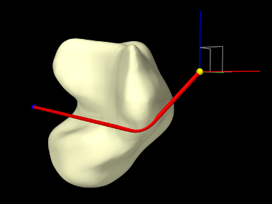
An example of wrapping around a general mesh is given by artisynth.demos.tutorial.TalusWrapping. It consists of a MultiPointSpring anchored by two via points and wrapped around a rigid body representing a talus bone. The code, with include directives omitted, is given below:
The mesh describing the talus bone is loaded from the file "data/TalusBone.obj" located beneath the model’s source directory (lines 11-19), with the utility class PathFinder used to determine the file path (Section 2.6). To ensure better wrapping behavior, the mesh is smoothed using Laplacian smoothing (line 21) before being used to create the rigid body (lines 23-27). The spring and its anchor points p0 and p1 are created between lines 30-49, with the talus added as a wrappable. The spring contains a single segment which is made wrappable using 100 knots, and initialized with an intermediate point (line 45) to ensure that it wraps around the bone in the correct way. Intermediate points are described in more detail in Section 9.4.
Render properties are set at lines 52-56; this includes turning off rendering for grid normals by zeroing the lineWidth render property for the grid component.
Finally, lines 59-67 create a control panel (Section 5.1) for interactively controlling a variety of properties, including gridSurfaceRendering for the talus (to see the grid isosurface instead of the bone mesh), resolution, maxResolution, renderGrid, and renderRanges for the grid component (to control its resolution and visibility), and drawKnots and wrapDamping for the spring (to make knots visible and to adjust the wrap damping as described in Section 9.6).
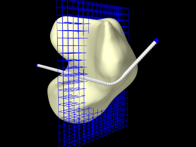
To run this example in ArtiSynth, select All demos > tutorial > TalusWrapping from the Models menu. Since all of the dynamic components are fixed, running the model will not cause any initial motion. However, while simulating, one can use the viewer’s graphical dragger fixtures (see the section “Transformer Tools” in the ArtiSynth User Interface Guide) to move p0 or p1 and hence pull the spring across the bone surface (Figure 9.9, left). One can also interactively adjust the property settings in the control panel to view the grid, isosurface, and knots, and the adjust the grid’s resolution. Figure 9.9, right, shows the model with renderGrid and drawKnots set to true and renderRanges set to "10:12 * *".
![[LOGO]](data:image/png;base64,iVBORw0KGgoAAAANSUhEUgAAAAsAAAAOCAYAAAD5YeaVAAAAAXNSR0IArs4c6QAAAAZiS0dEAP8A/wD/oL2nkwAAAAlwSFlzAAALEwAACxMBAJqcGAAAAAd0SU1FB9wKExQZLWTEaOUAAAAddEVYdENvbW1lbnQAQ3JlYXRlZCB3aXRoIFRoZSBHSU1Q72QlbgAAAdpJREFUKM9tkL+L2nAARz9fPZNCKFapUn8kyI0e4iRHSR1Kb8ng0lJw6FYHFwv2LwhOpcWxTjeUunYqOmqd6hEoRDhtDWdA8ApRYsSUCDHNt5ul13vz4w0vWCgUnnEc975arX6ORqN3VqtVZbfbTQC4uEHANM3jSqXymFI6yWazP2KxWAXAL9zCUa1Wy2tXVxheKA9YNoR8Pt+aTqe4FVVVvz05O6MBhqUIBGk8Hn8HAOVy+T+XLJfLS4ZhTiRJgqIoVBRFIoric47jPnmeB1mW/9rr9ZpSSn3Lsmir1fJZlqWlUonKsvwWwD8ymc/nXwVBeLjf7xEKhdBut9Hr9WgmkyGEkJwsy5eHG5vN5g0AKIoCAEgkEkin0wQAfN9/cXPdheu6P33fBwB4ngcAcByHJpPJl+fn54mD3Gg0NrquXxeLRQAAwzAYj8cwTZPwPH9/sVg8PXweDAauqqr2cDjEer1GJBLBZDJBs9mE4zjwfZ85lAGg2+06hmGgXq+j3+/DsixYlgVN03a9Xu8jgCNCyIegIAgx13Vfd7vdu+FweG8YRkjXdWy329+dTgeSJD3ieZ7RNO0VAXAPwDEAO5VKndi2fWrb9jWl9Esul6PZbDY9Go1OZ7PZ9z/lyuD3OozU2wAAAABJRU5ErkJggg==)