4.6 Distance Grids and Components
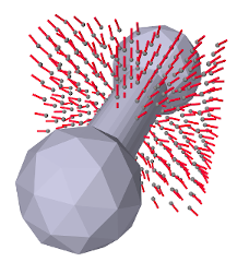
Distance grids, implemented by the class DistanceGrid, are currently used in ArtiSynth for both collision handling (Section 8.4.2) and spring and muscle wrapping around general surfaces (Section 9.3). A distance grid is a regular three dimensional grid that is used to interpolate a scalar distance field and its associated normals. For collision handling and wrapping purposes, this distance function is assumed to be signed and is used to estimate the penetration depth and associated normal direction of a point within some 3D object.
A distance grid consists of ![]() evenly spaced
vertices partitioning a volume into
evenly spaced
vertices partitioning a volume into ![]() cuboid
cells, with
cuboid
cells, with
The grid has overall widths ![]() ,
, ![]() ,
, ![]() along each axis, so
that the widths of each cell are
along each axis, so
that the widths of each cell are ![]() ,
, ![]() ,
, ![]() .
.
Scalar distances and normal vectors are stored at each vertex, and
interpolated at points within each cell using trilinear interpolation.
Distance values (although not normals) can also be interpolated quadratically over a composite quadratic cell composed of ![]() regular cells. This provides a smoother result than
trilinear interpolation and is currently used for muscle wrapping. To
ensure that all points within the grid can be assigned a unique
quadratic cell, the grid resolution is restricted so that
regular cells. This provides a smoother result than
trilinear interpolation and is currently used for muscle wrapping. To
ensure that all points within the grid can be assigned a unique
quadratic cell, the grid resolution is restricted so that ![]() ,
,
![]() ,
, ![]() are always even. Distance grids are typically generated
automatically from mesh data. More details on the actual
functionality of distance grids is contained in
the DistanceGrid API documentation.
are always even. Distance grids are typically generated
automatically from mesh data. More details on the actual
functionality of distance grids is contained in
the DistanceGrid API documentation.
When used within ArtiSynth, distance grids are generally contained within an encapsulating DistanceGridComp component, which maintains a mesh (or list of meshes) used to generate the grid, and exports properties for controlling its resolution, mesh fit, and visualization. For any object that implements CollidableBody (which includes RigidBody), its distance grid component can be obtained using the method
A distance grid maintains its own local coordinate system, which is related to world coordinates by a local-to-world transform that can be queried and set via the component methods setLocalToWorld() and getLocalToWorld(). For grids associated with a rigid body, the local coordinate system is synchronized with the rigid body’s coordinate system (which is queried and set via setPose() and getPose()). The grid’s axes are nominally aligned with the local coordinate system, although they can be subject to an additional orientation offset (e.g., see the description of the property fitWithOBB below).
By default, a DistanceGridComp generates its grid automatically
from its mesh data, within an axis-aligned bounding volume with the
resolutions ![]() ,
, ![]() ,
, ![]() chosen automatically. However, in
some cases it may be necessary to control the resolution explicitly.
DistanceGridComp exports the following properties to control
both the grid’s resolution and how it is fit around the mesh data:
chosen automatically. However, in
some cases it may be necessary to control the resolution explicitly.
DistanceGridComp exports the following properties to control
both the grid’s resolution and how it is fit around the mesh data:
- resolution
-
A vector of 3 integers that specifies the resolutions
 ,
,  ,
,  . If any value in this vector is set
 , then all values are set to zero and
the maxResolution property is used to determine the grid
divisions instead.
, then all values are set to zero and
the maxResolution property is used to determine the grid
divisions instead. - maxResolution
-
Sets the default maximum cell resolution that should be used when constructing the grid. This is the number of cells that should be used along the longest bounding volume axis, with the cell counts along the other axes adjusted to maintain a uniform cell size. If all three values of resolution are
 , those
will be used to specify the cell resolutions instead.
, those
will be used to specify the cell resolutions instead. - fitWithOBB
-
If true, offsets the orientation of the grid’s x, y, and z axes (with respect to local coordinates) to align with an oriented bounding box fit to the mesh. Otherwise, the grid axes are aligned with those of the local coordinate frame.
- marginFraction
-
Specifies the fractional amount by which the mesh should be extended with respect to a bounding box fit around the mesh(es). The default value is 0.1.
As with all properties, these can be set either interactively (either using a custom control panel or by selecting the component and then choosing Edit properties ... from the right-click context menu), or through their set/get accessor methods. For example, resolution and maxResolution can be set and queried via the methods:
 |
 |
 |
 |
 |
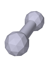
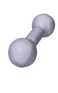
When used for either collisions or wrapping, the distance values interpolated by a distance grid are used to determine whether a point is inside or outside some 3D object, with the inside/outside boundary being the isosurface corresponding to a distance value of 0. This isosurface (which differs depending on whether trilinear or quadratic distance interpolation is used) therefore represents the effective collision boundary, and it may be somewhat different from the mesh surface used to generate it. It may be smoother, or may have discretization artifacts, depending on both the smoothness and complexity of the mesh and the grid’s resolution (Figure 4.15). It is therefore important to be able to visualize both the trilinear and quadratic isosurfaces. DistanceGridComp provides a number of properties to control this along with other aspects of grid visualization:
- renderProps
-
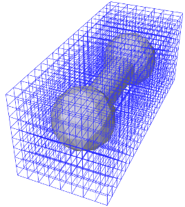
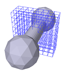
Render properties that control the colors, styles, and sizes (or widths) used to render faces, lines and points (Section 4.3). Point, line and edge properties are used for rendering grid vertices, normals, and cell edges, while face properties are used for rendering the isosurface. One can select which components are visible by zeroing appropriate render properties: zeroing pointRadius (or pointSize, if the pointStyle is POINT) disables drawing of the vertices; zeroing lineRadius (or lineWidth, if the lineStyle is LINE) disables drawing of the normals; and zeroing edgeWidth disables drawing of the cell edges. For an illustration, see Figure 4.16.
- renderGrid
-
If set to true, causes the grid’s vertices, normals and cell edges to be rendered, using the render properties as described above.
- renderRanges
-
Can be used to restrict which part of the distance grid is drawn. The value is a string which specifies the vertex ranges along the
 ,
,  , and
, and  axes. In general, the grid will have
  vertices along the , , and axes,
where
vertices along the , , and axes,
where  ,
,  , and
, and  are each one greater than the cell
resolutions , , and . The range string should contain
three range specifications, one for each axis, where each
specification is either * (all vertices), n:m (vertices in
the index range n to m, inclusive), or n (vertices
only at index n). A range specification of "* * *" (or
"*") means draw all vertices, which is the default
behavior. Other examples include:
are each one greater than the cell
resolutions , , and . The range string should contain
three range specifications, one for each axis, where each
specification is either * (all vertices), n:m (vertices in
the index range n to m, inclusive), or n (vertices
only at index n). A range specification of "* * *" (or
"*") means draw all vertices, which is the default
behavior. Other examples include:"* 7 *" all vertices along x and z, and those at index 7 along y "0 2 3" a single vertex at indices (0, 2, 3) "0:3 4:5 *" all vertices between 0 and 3 along x, and 4 and 5 along y
For an illustration, see Figure 4.16.
- renderSurface
-
If set to true, renders the grid’s isosurface, as determined by the surfaceType property. See Figure 4.15, right.
- surfaceType
-
Controls the interpolation used to form the isosurface rendered in response to the renderSurface property. QUADRATIC (the default) specifies a quadratic isosurface, while TRILINEAR specifies a trilinear isosurface.
- surfaceDistance
-
Controls the level set value used to determine the isosurface. To render the isosurface used for collision handling or muscle wrapping, this value should be 0.
When visualizing the isosurface for a distance grid, it is generally convenient to also turn off visualization for the meshes used to generate the grid. For RigidBody objects, this can be accomplished easily using the convenience property gridSurfaceRendering. If set true, it will cause the isosurface to be rendered instead of its mesh components. The isosurface type will be that indicated by the grid component’s surfaceType property, and the rendering will occur independently of the visibility settings for the meshes or the grid component.
![[LOGO]](data:image/png;base64,iVBORw0KGgoAAAANSUhEUgAAAAsAAAAOCAYAAAD5YeaVAAAAAXNSR0IArs4c6QAAAAZiS0dEAP8A/wD/oL2nkwAAAAlwSFlzAAALEwAACxMBAJqcGAAAAAd0SU1FB9wKExQZLWTEaOUAAAAddEVYdENvbW1lbnQAQ3JlYXRlZCB3aXRoIFRoZSBHSU1Q72QlbgAAAdpJREFUKM9tkL+L2nAARz9fPZNCKFapUn8kyI0e4iRHSR1Kb8ng0lJw6FYHFwv2LwhOpcWxTjeUunYqOmqd6hEoRDhtDWdA8ApRYsSUCDHNt5ul13vz4w0vWCgUnnEc975arX6ORqN3VqtVZbfbTQC4uEHANM3jSqXymFI6yWazP2KxWAXAL9zCUa1Wy2tXVxheKA9YNoR8Pt+aTqe4FVVVvz05O6MBhqUIBGk8Hn8HAOVy+T+XLJfLS4ZhTiRJgqIoVBRFIoric47jPnmeB1mW/9rr9ZpSSn3Lsmir1fJZlqWlUonKsvwWwD8ymc/nXwVBeLjf7xEKhdBut9Hr9WgmkyGEkJwsy5eHG5vN5g0AKIoCAEgkEkin0wQAfN9/cXPdheu6P33fBwB4ngcAcByHJpPJl+fn54mD3Gg0NrquXxeLRQAAwzAYj8cwTZPwPH9/sVg8PXweDAauqqr2cDjEer1GJBLBZDJBs9mE4zjwfZ85lAGg2+06hmGgXq+j3+/DsixYlgVN03a9Xu8jgCNCyIegIAgx13Vfd7vdu+FweG8YRkjXdWy329+dTgeSJD3ieZ7RNO0VAXAPwDEAO5VKndi2fWrb9jWl9Esul6PZbDY9Go1OZ7PZ9z/lyuD3OozU2wAAAABJRU5ErkJggg==)