4.7 Transforming geometry
Certain ArtiSynth components, including MechModel, implement the interface TransformableGeometry, which allows the geometric transformation of the component’s attributes (such as meshes, points, frame locations, etc.), along with its descendant components. The interface provides the method
where X is an AffineTransform3dBase that may be either a RigidTransform3d or a more general AffineTransform3d (Section 2.2).
 |
 |
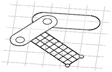 |
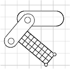
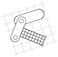
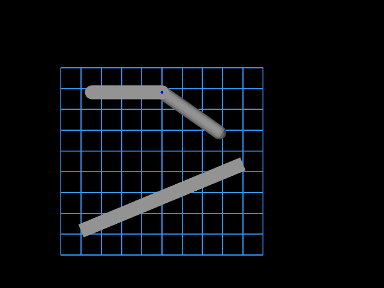
transformGeometry(X) can be used to translate, rotate, shear or scale components. It can be applied to an entire model or individual components. Unlike scaleDistance(), it actually changes the physical geometry and so may change the simulation behavior. For example, applying transformGeometry() to a RigidBody will cause the shape of its mesh to change, which will change its mass if its inertiaMethod property is set to DENSITY. Figure 4.17 shows a simplified illustration of both rigid and affine transformations being applied to a model.
The example below shows how to apply a transformation to a model in code. In it, a MechModel is first scaled by the factors 1.5, 2, and 3 along the x, y, and z axes, and then flipped upside down using a RigidTransform3d that rotates it by 180 degrees about the x axis:
The transform specified to transformGeometry is in world coordinates. If the component being transformed has its own local coordinate frame (such as a rigid body), and one wants to specify the transform in that local frame, then one needs to convert the transform from local to world coordinates. Let
be the local coordinate frame, and let
and
be the transform in world and body coordinates, respectively. Then
and so
As an example of converting a transform to world coordinates, suppose
we wish to scale a rigid body by ![]() ,
, ![]() , and
, and ![]() along its local
axes. The transformation could then be done as follows:
along its local
axes. The transformation could then be done as follows:
4.7.1 Nonlinear transformations
The TransformableGeometry interface also supports general, nonlinear geometric transforms. This can be done using a GeometryTransformer, which is an abstract class for performing general transformations. To apply such a transformation to a component, one can create and initialize an appropriate subclass of GeometryTransformer to perform the desired transformation, and then apply it using the static transform method of the utility class TransformGeometryContext:
At present, the following subclasses of GeometryTransformer are available:
- RigidTransformer
-
Implements rigid 3D transformations.
- AffineTransformer
-
Implements affine 3D transformations.
- FemGeometryTransformer
-
Implements a general transformation, using the deformation field induced by a finite element model.
TransformGeometryContext also supplies the following convenience methods to apply transformations to components or collections of components:
The last three of these methods create an instance of either RigidTransformer or AffineTransformer for the supplied AffineTransform3dBase. In fact, most TransformableGeometry components implement their transformGeometry(X) method as follows:
The FemGeometryTransformer class is derived from the class DeformationTransformer, which uses the single method getDeformation() to obtain deformation field information at a specified reference position:
If the deformation field is described by ![]() , then
for a given reference position
, then
for a given reference position ![]() (in undeformed coordinates),
this method should return the deformed position
(in undeformed coordinates),
this method should return the deformed position ![]() and the deformation gradient
and the deformation gradient
| (4.22) |
evaluated at ![]() .
.
FemGeometryTransformer obtains
![]() and
and ![]() from a
FemModel3d (see Section
6) whose elemental rest positions enclose the
components to be transformed, using the fact that a finite element
model creates an implied piecewise-smooth deformation field as it
deviates from its rest position. For each reference point
from a
FemModel3d (see Section
6) whose elemental rest positions enclose the
components to be transformed, using the fact that a finite element
model creates an implied piecewise-smooth deformation field as it
deviates from its rest position. For each reference point ![]() needed
by the transformation process, FemGeometryTransformer finds the
FEM element whose rest volume encloses
needed
by the transformation process, FemGeometryTransformer finds the
FEM element whose rest volume encloses ![]() , and then uses the
corresponding shape function coordinates to compute
, and then uses the
corresponding shape function coordinates to compute ![]() and
and ![]() from the element’s deformation. If the FEM model does not
enclose
from the element’s deformation. If the FEM model does not
enclose ![]() , the nearest element is used to determine the shape
function coordinates (however, this calculation becomes less accurate and
meaningful the farther
, the nearest element is used to determine the shape
function coordinates (however, this calculation becomes less accurate and
meaningful the farther ![]() is from the FEM model). Transformations based
on FEM models are further illustrated in Section
4.7.2, and by Figure
4.19. Full details on ArtiSynth finite
element models are given in Section 6.
is from the FEM model). Transformations based
on FEM models are further illustrated in Section
4.7.2, and by Figure
4.19. Full details on ArtiSynth finite
element models are given in Section 6.
Besides FEM models, there are numerous other ways to create deformation fields, such as radial basis functions, thin plate splines, etc. Some of these may be more appropriate for a particular application and can provide deformations that are globally smooth (as opposed to piecewise smooth). It should be relatively easy for an application to create its own subclass of DeformationTransformer to implement the deformation of choice by overriding the single getDeformation() method.
4.7.2 Example: the FemModelDeformer class
An FEM-based geometric transformation of a MechModel is facilitated by the class FemModelDeformer, which one can add to an existing RootModel to transform the geometry of a MechModel already located within that RootModel. FemModelDeformer subclasses FemModel3d to include a FemGeometryTransformer, and provides some utility methods to support the transformation process.
A FemModelDeformer can be added to a RootModel by adding the following code fragment to the end of the build() method:
When the deformer is created, its constructor searches the specified RootModel to locate the first top-level MechModel. It then creates a hexahedral FEM grid around this model, with maxn specifying the number of cells along the maximum dimension. Material and mass properties of the model are computed automatically from the underlying MechModel dimensions (but can be altered if necessary after construction). When added to the RootModel, the deformer becomes another top-level model that can be deformed independently of the MechModel to create the required deformation field, as described below. It also supplies application-defined menu items that appear under the Application menu in the ArtiSynth menu bar (see Section 5.6). The deformer’s createControlPanel() can also be used to create a ControlPanel (Section 5.1) that controls the visibility of the FEM model and the dynamic behavior of both it and the MechModel.
An example is defined in
artisynth.demos.tutorial.DeformedJointedCollide
where the JointedCollide example of Section 8.1.3 is extended to include a FemModelDeformer using the code described above.
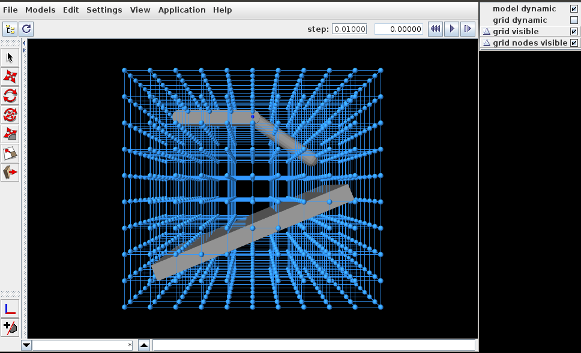
To load this example in ArtiSynth, select All demos > tutorial > DeformedJointedCollide from the Models menu. The model should load and initially appear as in Figure 4.18, where the control panel appears on the right.
The underlying MechModel (or "model") can now be transformed by first deforming the FEM model (or "grid") and then using the resulting deformation field to effect the transformation:
-
1.
Make the model non-dynamic and the grid dynamic by unchecking model dynamic and checking grid dynamic in the control panel. This means that when simulation is run, the model will be inert while the grid will respond physically.
-
2.
Deform the grid using simulation. One easy way to do this is to fix certain nodes, generally on or near the grid boundary, and then move some of these using the translation or transrotator tool while simulation is running. To fix a set of nodes, select them in the viewer, choose Edit properties ... from the right-click context menu, and then uncheck their dynamic property. To easily select a large number of nodes without also selecting model components or grid elements, one can specify FemNode in the selection filter widget. (See the sections “Transformer Tools” and “Selection filtering” in the ArtiSynth User Interface Guide.)
-
3.
After the grid has been deformed, choose deform from the Application menu in the ArtiSynth toolbar to transform the model. Afterwards, the transformation can be undone by choosing undo, and the grid can be reset by choosing reset grid.
-
4.
To run the deformed model after the transformation, it should again be made dynamic by checking model dynamic in the control panel. The grid itself can be made non-dynamic, and it and/or its nodes can be made invisible by unchecking grid visible and/or grid nodes visible in the control panel.
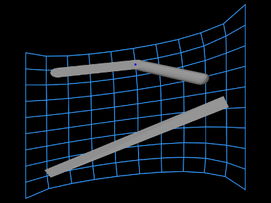
The result of a possible deformation is shown in Figure 4.19.
 |
 |
Note: FemModelDeformer is not intended to provide a general purpose solution to nonlinear geometric transformations. Rather, it is mainly intended to illustrate the capabilities of GeometryTransformer and the TransformableGeometry interface.
4.7.3 Implementation and behavior
As indicated above, the management of transforming the geometry for one or more components is handled by the TransformGeometryContext class. The transform operations themselves are carried out by this class’s apply() method, which (a) assembles all the components that need to be transformed, (b) performs the actual transform operations, (c) invokes any required updating actions on other components, and finally (d) notifies parent components of the change using a GeometryChangeEvent.
To support this, ArtiSynth components which implement TransformableGeometry must also supply the methods
The first method, addTransformableDependencies(context,flags), is called in step (a) to add to the context any additional components which should be transformed along with this component. This includes any descendants which should be transformed, since the transformation of these should not generally be done withintransformGeometry(gtr,context,flags).
The second method, transformGeometry(gtr,context,flags), is called in step (b) to perform the actual transformation on this component. It should use the supplied geometry transformer gtr to transform its attributes, as well as context to query what other components are also being transformed and to request any needed updating actions to be called in step (c). The flags argument specifies conditions associated with the transformation, which at the moment may currently include:
- TG_SIMULATING
-
The system is currently simulating, and therefore it may not be desirable to transform all attributes;
- TG_ARTICULATED
-
Rigid body articulation constraints should be enforced as the transform proceeds.
Full details for all this are given in the documentation for TransformGeometryContext.
The transforming behavior of a component is up to its implementing method, but the following rules are generally observed:
-
1.
Transformable descendants are also transformed, by using addTransformableDependencies() to add them to the context as described above;
-
2.
When the nodes of an FEM model (Section 6) are transformed, the rest positions are also transformed if the system is not simulating (i.e., if the TG_SIMULATING flag is not set). This also causes the mass of the adjacent nodes to be recomputed from the densities of the adjacent elements;
-
3.
When dynamic components are transformed, any attachments and constraints associated with them are updated appropriately, but only if the system is not simulating. Non-transforming dynamic components that are attached to transforming components are generally updated so as to follow the transforming components to which they are attached.
4.7.4 Use in model registration
Transforming model geometry can obviously be used as part of the process of creating subject-specific biomechanical and anatomical models. However, registration will generally require more than geometric transformation, since other properties, such as material stiffnesses, densities, and maximum forces will generally need to be adjusted as well. As a specific example, when applying a geometric transform to a model containing AxialSprings, the restLength properties of the springs will be unchanged, whereas the initial lengths may be, resulting in different applied forces and physical behavior.
![[LOGO]](data:image/png;base64,iVBORw0KGgoAAAANSUhEUgAAAAsAAAAOCAYAAAD5YeaVAAAAAXNSR0IArs4c6QAAAAZiS0dEAP8A/wD/oL2nkwAAAAlwSFlzAAALEwAACxMBAJqcGAAAAAd0SU1FB9wKExQZLWTEaOUAAAAddEVYdENvbW1lbnQAQ3JlYXRlZCB3aXRoIFRoZSBHSU1Q72QlbgAAAdpJREFUKM9tkL+L2nAARz9fPZNCKFapUn8kyI0e4iRHSR1Kb8ng0lJw6FYHFwv2LwhOpcWxTjeUunYqOmqd6hEoRDhtDWdA8ApRYsSUCDHNt5ul13vz4w0vWCgUnnEc975arX6ORqN3VqtVZbfbTQC4uEHANM3jSqXymFI6yWazP2KxWAXAL9zCUa1Wy2tXVxheKA9YNoR8Pt+aTqe4FVVVvz05O6MBhqUIBGk8Hn8HAOVy+T+XLJfLS4ZhTiRJgqIoVBRFIoric47jPnmeB1mW/9rr9ZpSSn3Lsmir1fJZlqWlUonKsvwWwD8ymc/nXwVBeLjf7xEKhdBut9Hr9WgmkyGEkJwsy5eHG5vN5g0AKIoCAEgkEkin0wQAfN9/cXPdheu6P33fBwB4ngcAcByHJpPJl+fn54mD3Gg0NrquXxeLRQAAwzAYj8cwTZPwPH9/sVg8PXweDAauqqr2cDjEer1GJBLBZDJBs9mE4zjwfZ85lAGg2+06hmGgXq+j3+/DsixYlgVN03a9Xu8jgCNCyIegIAgx13Vfd7vdu+FweG8YRkjXdWy329+dTgeSJD3ieZ7RNO0VAXAPwDEAO5VKndi2fWrb9jWl9Esul6PZbDY9Go1OZ7PZ9z/lyuD3OozU2wAAAABJRU5ErkJggg==)