8.1 Enabling collisions
This section describes how to enable collisions in code. However, it is also possible to set some aspects of collision behavior using the ArtiSynth GUI. See the section “Collision handling” in the ArtiSynth User Interface Guide.
ArtiSynth can simulate collisions between bodies that implement the interface Collidable. Collidable bodies are further subdivided into those that are rigid and those that are deformable, according to whether their isDeformable() method returns true. Rigid collidables include RigidBody, while deformable collidables include FEM models (FemModel3d), their mesh components (FemMeshComp), and skinned meshes (SkinMeshBody, Chapter 11). Because of the computational cost, collision detection is turned off by default and must be explicitly enabled when a model is built. Collisions can be enabled between specific pairs of bodies, or between general groupings of rigid and deformable bodies.
Collision handling is implemented by a model’s MechModel, which contains a CollisionManager subcomponent that keeps track of which bodies are colliding and computes the constraints and forces needed to enforce the collision behaviors. The collision manager itself can be accessed by the MechModel method
and can be used to query and set various collision properties, as described further below.
8.1.1 Collisions between specific bodies
As indicated above, collidable bodies are typically components such as rigid bodies or FEM models. Given two collidable bodies collidable0 and collidable1, the simplest way to enable collisions between them is with the MechModel methods
The first method enables collisions without friction, while the second enables collisions with friction as specified by mu, which is the coefficient of Coulomb (or dry) friction. The mu value is ignored if enabled is false. Specifying a mu value of 0 disables friction, and the friction coefficient can also be left undefined by specifying a mu value less than 0, in which case the coefficient is inherited from the global friction value accessed by the MechModel methods
More detailed control over collision behavior can be achieved using the method
where behavior is a CollisionBehavior object (Section8.2.1) that specifies both enabled and mu, along with other, more detailed collision properties (see Section 8.2.1).
The setCollisionBehavior() methods work by adding a CollisionBehavior object to the collision manager as a subcomponent. With the method setCollisionBehavior(collidable0,collidable1,behavior), the behavior object is created and supplied by the application. With the other methods, the behavior object is created automatically and returned by the method. Once a behavior has been specified, it can then be queried using
This method will return null if no behavior for the pair in question has been explicitly set using one of the setCollisionBehavior() methods.
One should normally avoid enabling collisions between bodies that are otherwise connected, for example, adjacent bodies in a linkage connected by joints, in order to avoid conflicts between the connection and the collision behavior. If collision interaction is required between parts of two connected bodies, this can be achieved in various ways as described in Section 8.3.
Because behaviors are proper components, it is not permissible to add them to the collision manager twice. Specifically, the following will produce an error:
   CollisionBehavior behav = new CollisionBehavior();
   behav.setDrawIntersectionContours (true);
   mech.setCollisionBehavior (col0, col1, behav);
   mech.setCollisionBehavior (col2, col3, behav); // ERROR
However, if desired, a new behavior can be created from an existing one:
   CollisionBehavior behav = new CollisionBehavior();
   behav.setDrawIntersectionContours (true);
   mech.setCollisionBehavior (col0, col1, behav);
   behav = new CollisionBehavior(behav);
   mech.setCollisionBehavior (col2, col3, behav); // OK
8.1.2 Default collisions between groups
For convenience, it is also possible to specify default collision behaviors between different groups of collidables.
The default collision behavior between all collidables can be controlled using the MechModel methods
where enabled, mu and behavior act as described in Section 8.1.1.
Because of the possible computational expense of collision detection, default collision behaviors should be used with care.
In addition, a default collision behavior can be set for generic groups of collidables using the MechModel methods
where group0 and group1 are static instances of Collidable.Group that represent the groups described in Table 8.1. The groups Collidable.Rigid and Collidable.Deformable denote collidables that are rigid and deformable, respectively. The group Collidable.AllBodies denotes both rigid and deformable bodies, and Collidable.Self is used to enable self-collision, which is described in greater detail in Section 8.3.2.
| Collidable group | description |
|---|---|
| Collidable.Rigid | rigid collidables (e.g., rigid bodies) |
| Collidable.Deformable | deformable collidables (e.g, FEM models) |
| Collidable.AllBodies | rigid and deformable collidables |
| Collidable.Self | enables self-intersection for compound deformable collidables |
| Collidable.All | rigid and deformable collidables and self-intersection |
A call to one of the setDefaultCollisionBehavior() methods will override the effects of previous calls. So for instance, the code sequence
will initially enable collisions between all bodies with a friction coefficient of 0, then disable collisions between deformable and rigid bodies, and finally re-enable collisions between all bodies with a friction coefficient of 0.2.
The default collision behavior between any pair of collidable groups can be queried using
where group0 and group1 are restricted to the primary groups Collidable.Rigid, Collidable.Deformable, and Collidable.Self, since individual behaviors are not maintained for the composite groups Collidable.AllBodies and Collidable.All.
Specific collision behaviors set using the setCollisionBehavior() methods of Section 8.1.1 will override any default collision settings. In addition, the second argument collidable1 of these methods can describe either an individual collidable, or one of the groups of Table 8.1. For example, the code fragment
will enable collisions between bodA and all deformable collidables (with friction 0.1), as well as femB and all deformable and rigid collidables (with friction 0.0), while specifically disabling collisions between bodA and femB.
To determine the actual behavior controlling collisions between two collidables (whether due to a default behavior or one specified using setCollisionBehavior()), one may use the method
where collidable0 and collidable1 must both be specific collidable components and cannot be a group (such as Collidable.Rigid or Collidable.All). If one of the collidables is a compound collidable (Section 8.3.2), or has a collidability setting (Section 8.2.2) that prevents collisions, there may be no consistent acting behavior, in which case the method returns null.
Collision behaviors take priority over each other in the following order:
-
1.
Behaviors specified using setCollisionBehavior() involving two specific collidables.
-
2.
Behaviors specified using setCollisionBehavior() involving one specific collidable and a group of collidables (indicated by a Collidable.Group), with later specifications taking priority over earlier ones.
-
3.
Default behaviors specified using setDefaultCollisionBehavior().
A collision behavior specified with setCollisionBehavior() can later be removed using
and all such behaviors in a MechModel can be removed with
Note that this latter call does not remove default behaviors specified with setDefaultCollisionBehavior().
8.1.3 Example: collision with a plane
A simple model illustrating collision between two jointed rigid bodies and a plane is defined in
artisynth.demos.tutorial.JointedCollide
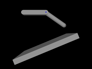
This model is simply a subclass of RigidBodyJoint that overrides the build() method to add an inclined plane and enable collisions between it and the two connected bodies:
The superclass build() method called at line 3 creates everything contained in RigidBodyJoint. The remaining code then alters that model: bodyB is set to be dynamic (line 5) so that it will fall freely, and an inclined plane is created from a thin box that is translated and rotated and then set to be non-dynamic (lines 8-11). Finally, collisions are enabled by setting the default collision behavior (line 14), and then specifically disabling collisions between bodyA and bodyB (line 15). As indicated above, the latter step is necessary because the joint would otherwise keep the two bodies in a permanent state of collision.
To run this example in ArtiSynth, select All demos > tutorial > JointedCollide from the Models menu. The model should load and initially appear as in Figure 8.1. Running the model (Section 1.5.3) will cause the jointed assembly to collide with and slide off the inclined plane.
8.1.4 Collisions for FEM models
Both FemModel3d and FemMeshComp implement Collidable. By default, a FemModel3d uses its surface mesh as the collision surface, while FemMeshComp will use the mesh it contains (although collisions will only occur if this is a triangular polygonal mesh).
Because FemModel3d contains other collidables as subcomponents, it is considered a compound collidable, as discussed further in Section 8.3.2. In particular, since FemMeshComp is also a Collidable, we can enable collisions with any embedded mesh inside an FEM. Any forces resulting from the collision are then automatically transferred back to the underlying nodes of the model using Equation (6.4).
Note: Collisions involving shell elements are not yet fully supported. This relates to the fact that shells are thin and can therefore pass through each other easily in a single time step, and also that meshes associated with shell elements are usually not closed. However, collisions should work properly if
- 1.
The collision meshes do not pass completely through each other in a single time step;
- 2.
Collisions do not occur near open mesh edges.
Restriction 2 can often be relaxed if the collider type is set to TRI_INTERSECTION (Section 8.4.2).
8.1.5 Example: FEM models and rigid bodies
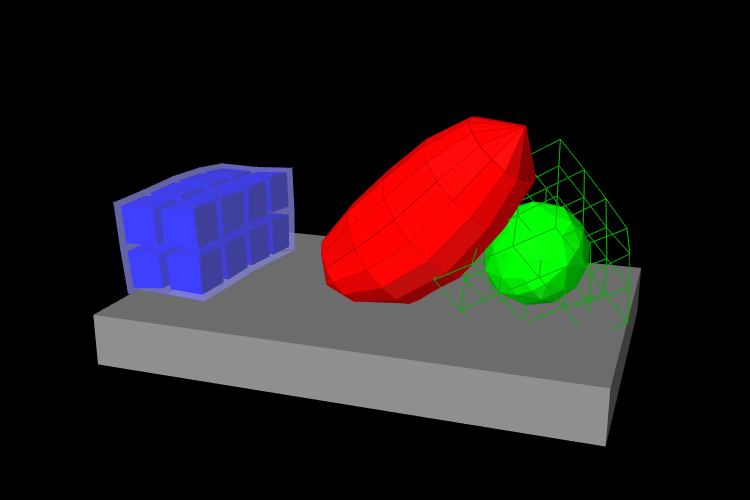
An example of FEM collisions is shown in Figure 8.2. The full source code can be found in the ArtiSynth repository under artisynth.demos.tutorial.FemCollisions. The model contains a rigid body table and three FEM models: a beam (blue), an ellipsoid (red), and a hex block containing an embedded spherical mesh (green). The collision-enabling code is as follows:
This enables collisions between the ellipsoid and the beam, table and embedded sphere, and between the table and the beam and embedded sphere. However, collisions are not enabled between the block itself and any other components; notice in the figure that the block surface passes through the table and ellipsoid.
![[LOGO]](data:image/png;base64,iVBORw0KGgoAAAANSUhEUgAAAAsAAAAOCAYAAAD5YeaVAAAAAXNSR0IArs4c6QAAAAZiS0dEAP8A/wD/oL2nkwAAAAlwSFlzAAALEwAACxMBAJqcGAAAAAd0SU1FB9wKExQZLWTEaOUAAAAddEVYdENvbW1lbnQAQ3JlYXRlZCB3aXRoIFRoZSBHSU1Q72QlbgAAAdpJREFUKM9tkL+L2nAARz9fPZNCKFapUn8kyI0e4iRHSR1Kb8ng0lJw6FYHFwv2LwhOpcWxTjeUunYqOmqd6hEoRDhtDWdA8ApRYsSUCDHNt5ul13vz4w0vWCgUnnEc975arX6ORqN3VqtVZbfbTQC4uEHANM3jSqXymFI6yWazP2KxWAXAL9zCUa1Wy2tXVxheKA9YNoR8Pt+aTqe4FVVVvz05O6MBhqUIBGk8Hn8HAOVy+T+XLJfLS4ZhTiRJgqIoVBRFIoric47jPnmeB1mW/9rr9ZpSSn3Lsmir1fJZlqWlUonKsvwWwD8ymc/nXwVBeLjf7xEKhdBut9Hr9WgmkyGEkJwsy5eHG5vN5g0AKIoCAEgkEkin0wQAfN9/cXPdheu6P33fBwB4ngcAcByHJpPJl+fn54mD3Gg0NrquXxeLRQAAwzAYj8cwTZPwPH9/sVg8PXweDAauqqr2cDjEer1GJBLBZDJBs9mE4zjwfZ85lAGg2+06hmGgXq+j3+/DsixYlgVN03a9Xu8jgCNCyIegIAgx13Vfd7vdu+FweG8YRkjXdWy329+dTgeSJD3ieZ7RNO0VAXAPwDEAO5VKndi2fWrb9jWl9Esul6PZbDY9Go1OZ7PZ9z/lyuD3OozU2wAAAABJRU5ErkJggg==)