6.4 Connecting FEM models to other components
To couple FEM models to other dynamic components, the “attachment” mechanism described in Section 1.2.3 is used. This involves creating and adding to the model attachment components, which are instances of DynamicAttachment, as described in Section 3.9. Common point-based attachment classes are listed in Table 6.4.
| Attachment | Description |
|---|---|
| PointParticleAttachment | Attaches one “point” to one “particle” |
| PointFrameAttachment | Attaches one “point” to one “frame” |
| PointFem3dAttachment | Attaches one “point” to a linear combination of FEM nodes |
FEM models are connected to other model components by attaching their nodes to various components. This can be done by creating an attachment object of the appropriate type, and then adding it to the MechModel using
There are also convenience routines inside MechModel that will create the appropriate attachments automatically (see Section 3.9.1).
All attachments described in this section are based around FEM nodes. However, it is also possible to attach frame-based components (such as rigid bodies) directly to an FEM, as described in Section 6.6.
6.4.1 Connecting nodes to rigid bodies or particles
Since FemNode3d is a subclass of Particle, the same methods described in Section 3.9.1 for attaching particles to other particles and frames are available. For example, we can attach an FEM node to a rigid body using either a statement of the form
or the following equivalent statement which does the same thing:
Both of these create a PointFrameAttachment between a rigid body (called body) and an FEM node (called node) and then adds it to the MechModel mech.
6.4.2 Example: connecting a beam to a block
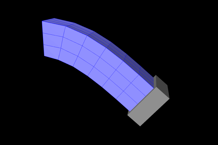
The following model demonstrates attaching an FEM beam to a rigid block.
This model extends the FemBeam example of Section 6.2.5. The build() method then creates and adds a RigidBody block (lines 18–20). On line 21, the block is repositioned to the side of the beam to prepare for the attachment. On lines 24–28, all right-most nodes of the beam are then set to be attached to the block using a PointFrameAttachment. In this case, the attachments are explicitly created. They could also have been attached using
6.4.3 Connecting nodes directly to elements
Typically, nodes do not align in a way that makes it
possible to connect them to other FEM models and/or points based on
simple point-to-node attachments. Instead, we use a different
mechanism that allows us to attach a point to an arbitrary location
within an FEM model. This is done using an attachment component of
type
PointFem3dAttachment, which
implements an attachment where the position ![]() and velocity
and velocity ![]() of the
attached point is determined by a weighted sum of the positions
of the
attached point is determined by a weighted sum of the positions ![]() and velocities
and velocities ![]() of selected fem nodes:
of selected fem nodes:
| (6.3) |
Any force ![]() acting on the attached point is then propagated back
to the nodes, according to the relation
acting on the attached point is then propagated back
to the nodes, according to the relation
| (6.4) |
where ![]() is the force acting on node
is the force acting on node ![]() due to
due to ![]() . This
relation can be derived based on the conservation of energy.
If
. This
relation can be derived based on the conservation of energy.
If ![]() is embedded within a single element, then the
is embedded within a single element, then the ![]() are
simply the element nodes and the
are
simply the element nodes and the ![]() are corresponding shape
function values; this is known as an element-based attachment.
On the other hand, as described below, it is sometimes desirable to
form an attachment using a more general set of nodes that extends
beyond a single element; this is known as a nodal-based
attachment (Section 6.4.8).
are corresponding shape
function values; this is known as an element-based attachment.
On the other hand, as described below, it is sometimes desirable to
form an attachment using a more general set of nodes that extends
beyond a single element; this is known as a nodal-based
attachment (Section 6.4.8).
An element-based attachment can be created using a code fragment of the form
First, a PointFem3dAttachment is created for the point pnt. Next, setFromElement() is used to determine the nodal weights within the element elem for the specified position (which in this case is simply the point’s current position). To do this, it computes the “natural coordinates” of the position within the element. For this to be guaranteed to work, the position should be on or inside the element. If natural coordinates cannot be found, the method will return false and the nearest estimated coordinates will be used instead. However, it is sometimes possible to find natural coordinates outside a given element as long as the shape functions are well-defined. Finally, the attachment is added to the model.
More conveniently, the exact same functionality is provided by the attachPoint() method in MechModel:
This creates an attachment identical to that created by the previous code fragment.
Often, one does not want to have to determine the element to which a point should be attached. In that case, one can call
or, equivalently,
This will find the nearest element to the node in question and use that to create the attachment. If the node is outside the FEM model, then it will be attached to the nearest point on the FEM’s surface.
6.4.4 Example: connecting two FEMs together
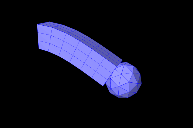
The following model demonstrates how to attach two FEM models together:
This example can be found in artisynth.demos.tutorial.FemBeamWithFemSphere. The model extends FemBeam, adding a finite element sphere and coupling them together. The sphere is created and added on lines 18–28. It is read from TetGen-generated files using the TetGenReader class. The model is then scaled to match the dimensions of the current model, and transformed to the right side of the beam. To create attachments, the code first checks for any nodes that belong to the sphere that fall inside the beam using the FemModel3d.findContainingElement(Point3d) method (line 36), which returns the containing element if the point is inside the model, or null if the point is outside. Internally, this spatial search uses a bounding volume hierarchy for efficiency (see BVTree and BVFeatureQuery). If the point is contained within the beam, then mech.attachPoint() is used to attach it to the nodes of the element (line 39).
6.4.5 Finding which nodes to attach
While it is straightforward to connect nodes to rigid bodies or other FEM nodes or elements, it is often necessary to determine which nodes to attach. This was evident in the example of Section 6.4.4, which attached nodes of an FEM sphere that were found to be inside an FEM beam.
As in that example, finding the nodes to attach can often be done using geometric queries. For example, we often select nodes based on how close they are to the other body we wish to attach to.
Various proximity queries are available for this task. To find the distance of a point to a polygonal mesh, we can use the following PolygonalMesh methods,
| double distanceToPoint(Point3d pnt) |
Returns the distance of pnt to the mesh. |
| int pointIsInside (Point3d pnt) |
Returns true if pnt is inside the mesh. |
where the latter method returns 1 if the point is inside and 0 otherwise. For checking the distance of an FEM node, pnt can be obtained from node.getPosition() (or possibly node.getRestPosition()). For example, to find all nodes within a distance tol of the surface of a rigid body, we could use the code fragment:
If we want to check only nodes that lie on the FEM surface, then we can filter them using the FemModel3d method isSurfaceNode():
Most of the mesh-based query methods work only for triangular meshes. The PolygonalMesh method isTriangular() can be used to determine if the mesh is triangular. If it is not, it can made triangular by calling triangulate(), although in general this should be done during model construction before the mesh-based component has been added to the model.
For connecting an FEM model to another FEM model, FemModel3d provides a number of query methods:
| Nearest element queries: | |
|---|---|
| FemElement3dBase findNearestElement( Point3d near, Point3d pnt) |
Find nearest element (shell or volumetric) to pnt. |
| FemElement3dBase findNearestElement( Point3d near, Point3d pnt, ElementFilter filter) |
Find nearest filtered element (shell or volumetric) to pnt. |
| FemElement3dBase findNearestSurfaceElement( Point3d near, Point3d pnt) |
Find nearest surface element (shell or volumetric) to pnt. |
| FemElement3d findNearestVolumetricElement ( Point3d near, Point3d pnt) |
Find nearest volumetric element to pnt. |
| ShellElement3d findNearestShellElement ( Point3d near, Point3d pnt) |
Find nearest shell element to pnt. |
| FemElement3d findContainingElement(Point3d pnt) |
Find volumetric element (if any) containing pnt. |
| Nearest node queries: | |
|---|---|
| FemNode3d findNearestNode ( Point3d pnt, double maxDist) |
Find nearest node to pnt that is within maxDist. |
| ArrayList<FemNode3d> findNearestNodes ( Point3d pnt, double maxDist) |
Find all nodes that are within maxDist of pnt. |
All the above queries are based on the FEM model’s current nodal
positions. The method
findNearestElement(near,pnt,filter) allows the application to
specify
a FemModel.ElementFilter to
restrict the elements that are searched.
The argument near that appears in some of the queries is an optional argument which, if not null, returns the location of the corresponding nearest point on the element. The distance from pnt to the element can then be found using
near.distance (pnt);
If the resulting distance is 0, then the point is on or inside the element. Otherwise, the point is outside the element, and if no element filters were used in the query, outside the FEM model itself.
Typically, it is preferred to attach a point to an element only if it lies on or inside an element. However, it is possible to attach points outside an element as long as the system is able to determine appropriate element “coordinates” for that point (which it may not be able to do if the point is far away). In addition, the motion behavior of an exterior attached point may sometimes appear counterintuitive.
The FemModel3d element and node queries can be used in a variety of ways.
findNearestNodes() can be used to find all nodes within a certain distance of a point, as part of the process of making nodal-based attachments (Section 6.4.8).
findNearestNode() is used in the FemMuscleBeam example (Section 6.9.5) to determine if a desired muscle point is near enough to a node to use that node directly, or if a marker should be created.
As another example, suppose we wish to connect the surface nodes of an FEM model femA to the surface elements of another model femB if they lie within a prescribed distance tol of the surface of femB. Then we could use the following code:
Finally, it is possible to identify nodes on the surface of an FEM model according to whether they belong to specific features, such as a smooth patch or a sharp edge line. Methods for doing this are provided as static methods in the class FemQuery, and include:
| Feature based node queries: | |
|---|---|
| ArrayList<FemNode3d> findPatchNodes ( FemModel3d fem, FemNode3d node0, double maxBendAng) |
Find nodes in patch defined by a maximum bend angle. |
| ArrayList<FemNode3d> findPatchBoundaryNodes ( FemModel3d fem, FemNode3d node0, double maxBendAng) |
Find the border nodes of a patch. |
| ArrayList<FemNode3d> findEdgeLineNodes ( FemModel3d fem, FemNode3d node0, double minBendAng, double maxEdgeAng, double allowBranching) |
Find the nodes along an edge defined by a minimum bend angle. |
Details of how these methods work are given in their API documentation. They use the notion of a bend angle, which is the absolute value of the angle between two faces about their common edge. A patch is defined by a collection of faces whose bend angles do not exceed a minimum value, while an edge line is a collection of edges with bend angles not below a maximum value. The feature methods start with an initial node (node0) and then grow the requested feature out from there. For example, suppose we have a regular hexahedral FEM grid, and we wish to find all the nodes on one of the faces. If we know one of the nodes on the face, then we can find all of the nodes using findPatchNodes:
Note that the feature query above uses a maximum bend angle of
![]() . Because grid faces are flat, this choice is somewhat
arbitrary; any angle larger than 0 (within machine precision) would also
work.
. Because grid faces are flat, this choice is somewhat
arbitrary; any angle larger than 0 (within machine precision) would also
work.
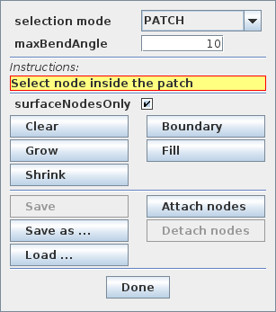
6.4.6 Selecting nodes in the viewer
Often, it is most convenient to select nodes in the ArtiSynth viewer. For this, a node selection tool is available (Figure 6.8), as described in the section “Selecting FEM nodes” of the ArtiSynth User Interface Guide). It allows nodes to be selected in various ways, including the usual click, drag box and elliptical selection tools, as well as specialized operations that select nodes based on patches, edge lines, and distances to other bodies. Once nodes have been selected, their numbers can be saved to a node number file which can then be read by a model’s build() method to determine which nodes to connect to some body.
Node number files are text files with a very simple format, consisting of integers (the node numbers), separated by white space. There is no limit to how many numbers can appear on a line but typically this is limited to ten or so to make the file more readable. Optionally, the numbers can be surrounded by square brackets ([ ]). The special character ‘#’ is a comment character, commenting out all characters from itself to the end of the current line. For a file containing the node numbers 2, 12, 4, 8, 23 and 47, the following formats are all valid:
Once node numbers have been identified in the viewer and saved in a file, they can be read by the build() method using a NodeNumberReader. For convenience, this class supplies two static methods for extracting the FEM nodes specified by the numbers in a file:
| static ArrayList<FemNode3d> read( File file, FemModel3d fem) |
Returns nodes in fem corresponding to file’s numbers. |
| static ArrayList<FemNode3d> read( String filePath, FemModel3d fem) |
Returns nodes in fem corresponding to file’s numbers. |
Extracted nodes can be used to set boundary conditions or form connections with other bodies. For example, suppose we wish to connect a face of an FEM model fem to a rigid body block, using a set of nodes specified in a file called faceNodes.txt. A code fragment to accomplish this could be the following:
The process of selecting nodes in the viewer, saving them in a file, and using them in a model can be done iteratively: if the selected nodes need to be adjusted, one can reopen the node selection tool, load the selection from file, adjust the selection, and resave the file, without needing to make any modifications to the model’s build() code.
If desired, one can also determine a set of nodes in code, and then write their numbers to a file using the class NodeNumberWriter, which supplies static methods for writing number files:
| static void write( String filePath, Collection<FemNode3d> nodes) |
Writes the numbers of nodes to the specified file. |
| static void write( File file, Collection<FemNode3d> nodes) |
Writes the numbers of nodes to file. |
| static void write( File file, Collection<FemNode3d> nodes, int maxCols, int flags) |
Writes the numbers of nodes to file, using the specified number of columns and format flags. |
For example:
6.4.7 Example: two bodies connected by an FEM “spring”
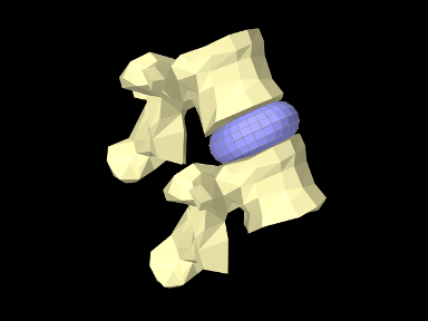
The LumbarFrameSpring example in Section 3.7.4 uses a frame spring to connect two simplified lumbar vertebrae. However, it is also possible to use an FEM model in place of a frame spring, possibly providing a more realistic model of the intervertebral disc. A simple model which does this is defined in
artisynth.demos.tutorial.LumbarFEMDisk
The initial source code is similar to that for LumbarFrameSpring, but differs in the section where the FEM disk replaces the FrameSpring:
The simplified FEM model representing the “disk” is created at lines 57-61, using a torus-shaped model created by FemFactory. It is then repositioned using transformGeometry() ( Section 4.7) to place it between the vertebrae (line 64-66). After the FEM model is positioned, we find which nodes are within a distance tol of each vertebral surface and attach them to the appropriate body (lines 69-81).
To run this example in ArtiSynth, select All demos > tutorial > LumbarFEMDisk from the Models menu. The model should load and initially appear as in Figure 6.9. The behavior is best seen by running the model and using the pull controller to exert forces on the upper vertebra.
6.4.8 Nodal-based attachments
The example of Section 6.4.4 uses element-based attachments to connect the nodes of one FEM to elements of another. As mentioned above, element-based attachments assume that the attached point is associated with a specific FEM model element. While this often gives good results, there are situations where it may be desirable to distribute the connection more broadly among a larger set of nodes.
In particular, this is sometimes the case when connecting FEM models to point-to-point springs. The end-point of such a spring may end up exerting a large force on the FEM, and then if the number of nodes to which the end-point is attached are too small, the resulting forces on these nodes (Equation 6.4) may end up being too large. In other words, it may be desirable to distribute the spring’s force more evenly throughout the FEM model.
To handle such situations, it is possible to create a nodal-based attachment in which the nodes and weights are explicitly specified. This involves explicitly creating a PointFem3dAttachment for the point or particle to be attached and the specifying the nodes and weights directly,
where nodes and weights are arrays of FemNode and double, respectively. It is up to the application to determine these.
PointFem3dAttachment provides several methods for explicitly specifying nodes and weights. The signatures for these include:
The last two methods determine the weights automatically, using an
inverse-distance-based calculation in which each weight ![]() is initially computed as
is initially computed as
| (6.4) |
where ![]() is the distance from node
is the distance from node ![]() to pos and
to pos and
![]() is the maximum distance. The weights are then
adjusted to ensure that they sum to one and that the weighted sum of
the nodes equals pos. In some cases, the specified nodes
may not provide enough support for the last condition to be
met, in which case the methods return false.
is the maximum distance. The weights are then
adjusted to ensure that they sum to one and that the weighted sum of
the nodes equals pos. In some cases, the specified nodes
may not provide enough support for the last condition to be
met, in which case the methods return false.
6.4.9 Example: element vs. nodal-based attachments
The model demonstrating the difference between element and nodal-based attachments is defined in
artisynth.demos.tutorial.PointFemAttachment
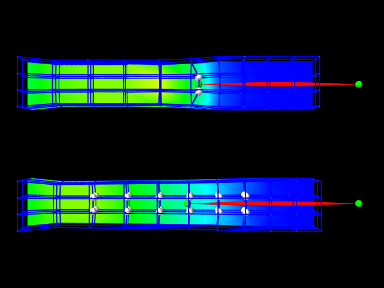
It creates two FEM models, each with a single point-to-point spring attached to a particle at their center. The model at the top (fem1 in the code below) is connected to the particle using an element-based attachment, while the lower model (fem2 in the code) is connected using a nodal-based attachment with a larger number of nodes. Figure 6.10 shows the result after the model is run until stable. The element-based attachment results in significantly higher deformation in the immediate vicinity around the attachment, while for the nodal-based attachment, the deformation is distributed much more evenly through the model.
The build method and some of the auxiliary code for this model is shown below. Code for the other auxiliary methods, including addFem(), addParticle(), addSpring(), and setAttachedNodesWhite(), can be found in the actual source file.
The build() method begins by creating a MechModel and then adding to it two FEM beams (created using the auxiliary method addFem()). Rendering of each FEM model’s surface is then set up to show strain values (setSurfaceRendering(), lines 41 and 43). The surface meshes themselves are also redefined to exclude the frontmost elements, allowing the strain values to be displayed closer to the model centers. This redefinition is done using calls to createSurfaceMesh() (lines 40, 41) with a custom ElementFilter defined at lines 3-12.
Next, the end-point particles for the axial springs are created (using the auxiliary method addParticle(), lines 46-49), and particle m1 is attached to fem1 using mech.attachPoint() (line 52), which creates an element-based attachment at the point’s current location. Point m2 is then attached to fem2 using a nodal-based attachment. The nodes for these are collected as the union of all nodes for a specified set of elements (lines 58-59, and the method collectNodes() defined at lines 16-25). These are then used to create a nodal-based attachment (lines 61-63), where the weights are determined automatically using the method associated with equation (6.4).
Finally, the springs are created (auxiliary method addSpring(), lines 66-67), the nodes associated for each attachment are set to render as white spheres (setAttachedNodesWhite(), lines 70-71), and the particles are set to render as green spheres.
To run this example in ArtiSynth, select All demos > tutorial > PointFemAttachment from the Models menu. Running the model will cause it to settle into the state shown in Figure 6.10. Selecting and dragging one of the spring anchor points at the right will cause the spring tension to vary and further illustrate the difference between the element and nodal-based attachments.
![[LOGO]](data:image/png;base64,iVBORw0KGgoAAAANSUhEUgAAAAsAAAAOCAYAAAD5YeaVAAAAAXNSR0IArs4c6QAAAAZiS0dEAP8A/wD/oL2nkwAAAAlwSFlzAAALEwAACxMBAJqcGAAAAAd0SU1FB9wKExQZLWTEaOUAAAAddEVYdENvbW1lbnQAQ3JlYXRlZCB3aXRoIFRoZSBHSU1Q72QlbgAAAdpJREFUKM9tkL+L2nAARz9fPZNCKFapUn8kyI0e4iRHSR1Kb8ng0lJw6FYHFwv2LwhOpcWxTjeUunYqOmqd6hEoRDhtDWdA8ApRYsSUCDHNt5ul13vz4w0vWCgUnnEc975arX6ORqN3VqtVZbfbTQC4uEHANM3jSqXymFI6yWazP2KxWAXAL9zCUa1Wy2tXVxheKA9YNoR8Pt+aTqe4FVVVvz05O6MBhqUIBGk8Hn8HAOVy+T+XLJfLS4ZhTiRJgqIoVBRFIoric47jPnmeB1mW/9rr9ZpSSn3Lsmir1fJZlqWlUonKsvwWwD8ymc/nXwVBeLjf7xEKhdBut9Hr9WgmkyGEkJwsy5eHG5vN5g0AKIoCAEgkEkin0wQAfN9/cXPdheu6P33fBwB4ngcAcByHJpPJl+fn54mD3Gg0NrquXxeLRQAAwzAYj8cwTZPwPH9/sVg8PXweDAauqqr2cDjEer1GJBLBZDJBs9mE4zjwfZ85lAGg2+06hmGgXq+j3+/DsixYlgVN03a9Xu8jgCNCyIegIAgx13Vfd7vdu+FweG8YRkjXdWy329+dTgeSJD3ieZ7RNO0VAXAPwDEAO5VKndi2fWrb9jWl9Esul6PZbDY9Go1OZ7PZ9z/lyuD3OozU2wAAAABJRU5ErkJggg==)