6.6 Frame attachments
It is also possible to attach frame components, including rigid bodies, directly to FEM models, using the attachment component FrameFem3dAttachment. Analogously to PointFem3dAttachment, the attachment is implemented by connecting the frame to a set of FEM nodes, and attachments can be either element-based or nodal-based. The frame’s origin is computed in the same way as for point attachments, using a weighted sum of node positions (Equation 6.3), while the orientation is computed using a polar decomposition on a deformation gradient determined from either element shape functions (for element-based attachments) or a Procrustes type analysis using nodal rest positions (for nodal-based attachments).
An element-based attachment can be created using either a code fragment of the form
or, equivalently, the attachFrame() method in MechModel:
This attaches the frame frame to the nodes of the FEM element elem. As with PointFem3dAttachment, if the frame’s origin is not inside the element, it may not be possible to accurately compute the internal nodal weights, in which case setFromElement() will return false.
In order to have the appropriate element located automatically, one can instead use
or, equivalently,
As with point-to-FEM attachments, it may be desirable to create a nodal-based attachment in which the nodes and weights are not tied to a specific element. The reasons for this are generally the same as with nodal-based point attachments (Section 6.4.8): the need to distribute the forces and moments acting on the frame across a broader set of element nodes. Also, element-based frame attachments use element shape functions to determine the frame’s orientation, which may produce slightly asymmetric results if the frame’s origin is located particularly close to a specific node.
FrameFem3dAttachment provides several methods for explicitly specifying nodes and weights. The signatures for these include:
Unlike their counterparts in PointFem3dAttachment, the first two methods also require the current desired pose of the frame TFW (in world coordinates). This is because while nodes and weights will unambiguously specify the frame’s origin, they do not specify the desired orientation.
6.6.1 Example: attaching frames to an FEM beam
A model illustrating how to connect frames to an FEM model is defined in
artisynth.demos.tutorial.FrameFemAttachment
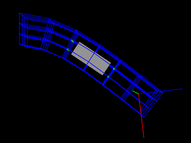
It creates an FEM beam, along with a rigid body block and a massless coordinate frame, that are then attached to the beam using nodal and element-based attachments. The build method is shown below:
Lines 3-22 create a MechModel and populate it with an FEM beam and a rigid body box. Next, a basic Frame is created, with a specified pose and an axis length of 0.3 (to allow it to be seen), and added to the MechModel (lines 25-28). It is then attached to the FEM beam using an element-based attachment (line 30). Meanwhile, the box is attached to using a nodal-based attachment, created from all the nodes associated with elements 22 and 31 (lines 33-36). Finally, all attachment nodes are set to be rendered as green spheres (lines 39-41).
To run this example in ArtiSynth, select All demos > tutorial > FrameFemAttachment from the Models menu. Running the model will cause it to settle into the state shown in Figure 6.12. Forces can interactively be applied to the attached block and frame using the pull tool, causing the FEM model to deform (see the section “Pull Manipulation” in the ArtiSynth User Interface Guide).
6.6.2 Attached frames
A FemAttachedFrame is an AttachedFrame that is connected to a FemModel3d, analogous to FrameAttachedFrame components that are connected to Frames (Section 3.10.1). The attachment is element-based: the frame’s position and orientation track a weighted combination of the surrounding FEM nodes, using natural coordinates within the enclosing (or nearest) element. The frame therefore moves and changes orientation as the FE model deforms.
FemAttachedFrame objects can be created using the constructors
| FemAttachedFrame () | |
| FemAttachedFrame (RigidTransform3d TFW) | |
| FemAttachedFrame (FemElement3dBase elem, RigidTransform3d TFW) |
where FemAttachedFrame() creates a default frame with no attachment, FemAttachedFrame(TFW) sets the initial world pose to TFW, and FemAttachedFrame(elem,TFW) also attaches the frame to the specified element. Once created, the nature of the FE attachment can be set or changed using
| void setFromFem (FemModel3d fem) |
Attaches to the nearest element in fem. |
| void setFromElement (FemElement3dBase elem) |
Attaches to elem using natural coordinates computed from the frame’s current pose. |
| boolean setFromNodes ( Collection<FemNode3d> nodes, VectorNd weights) |
Attaches to the specified nodes using the given weights. |
| boolean setFromNodes ( FemNode3d[] nodes, double[] weights) |
Attaches to the specified nodes using the given weights. |
| boolean setFromNodes (Collection<FemNode3d> nodes) |
Attaches to the specified nodes using inverse-distance weighting based on the frame’s current pose. |
| boolean setFromNodes (FemNode3d[] nodes) |
Attaches to the specified nodes using inverse-distance weighting based on the frame’s current pose. |
The setFromNodes() methods mirror those available for FemMarker (Section 6.4.8): the first two take explicit weights, while the last two determine weights automatically using inverse-distance weighting as described by equation (6.4).
Once created, the attached frame must be added to the MechModel hierarchy. One choice is to add them directly to the FE model to which they are attached. Each FemModel3d maintains an attachedFrames container, which may be managed using the following FemModel3d methods:
| void addAttachedFrame (FemAttachedFrame frm) |
Adds an existing frame, attaching it to the nearest element if not already attached to this model. |
| void addAttachedFrame ( FemAttachedFrame frm, FemElement3dBase elem) |
Adds an existing frame, attaching it to the specified element. |
| FemAttachedFrame addAttachedFrame ( RigidTransform3d TFW) |
Creates a new FemAttachedFrame located at world pose |
| boolean removeAttachedFrame (FemAttachedFrame frm) |
Removes frm from the list; returns true if present. |
| void clearAttachedFrames () |
Removes all frames from the attachedFrames list. |
| RenderableComponentList<FemAttachedFrame> getAttachedFrames () |
Returns the attachedFrames sub-list. |
Alternatively, attached frames can be added to the MechModel’s frames container, which is managed using the MechModel methods
| void addFrame (Frame frame) |
Adds frame frame to the container. |
| boolean removeFrame (Frame frame) |
Removes frame frame from the container. |
| void clearFrames() |
Removes all frames. |
| RenderableComponentList<Frame> frames() |
Returns the frames container. |
6.6.3 Example: attached frames for an FE model
The following model demonstrates how to add FemAttachedFrames to an FEM beam:
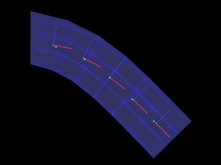
This example can be found in artisynth.demos.tutorial.FemAttachedFrames.
It extends FemBeam (Section 6.2.5), adding five evenly-spaced
FemAttachedFrames along the beam’s local ![]() -axis (lines 20–27). Each
frame is positioned at a world-coordinate pose computed from the beam’s length,
and added to the FEM model using fem.addAttachedFrame(TFW), which
automatically finds and attaches to the nearest element. The frames are
rendered as solid arrow triads with an axis length of 0.12. Finally, the FEM
surface is made semi-transparent (line 29) so the embedded frames are visible.
-axis (lines 20–27). Each
frame is positioned at a world-coordinate pose computed from the beam’s length,
and added to the FEM model using fem.addAttachedFrame(TFW), which
automatically finds and attaches to the nearest element. The frames are
rendered as solid arrow triads with an axis length of 0.12. Finally, the FEM
surface is made semi-transparent (line 29) so the embedded frames are visible.
To run this example in ArtiSynth, select All demos > tutorial > FemAttachedFrames from the Models menu. The model should load and initially appear as in Figure 6.13. Running the model will cause the beam to fall under gravity, with all attached frames moving and rotating to track the deformation of the beam.
6.6.4 Adding joints to FEM models
The ability to connect frames to FEM models, as described in Section 6.6, makes it possible to interconnect different FEM models directly using joints, as described in Section 3.4. This is done internally by using FrameFem3dAttachments to connect frames C and D of the joint (Figure 3.9) to their respective FEM models.
As indicated in Section 3.4.3, most joints have a constructor of the form
that creates a joint connecting bodyA to bodyB, with the initial pose of the D frame given (in world coordinates) by TDW. The same body and transform settings can be made on an existing joint using the setBodies() methods also described in Section 3.4.3. For these constructors and methods, it is possible to specify FEM models for bodyA and/or bodyB. Internally, the joint then creates a FrameFem3dAttachment to connect frame C and/or D of the joint (See Figure 3.9) to the corresponding FEM model.
However, unlike joints involving rigid bodies or frames, there are no
associated ![]() or
or ![]() transforms (since there is no fixed
frame within an FEM to define such transforms). Methods or
constructors which utilize
transforms (since there is no fixed
frame within an FEM to define such transforms). Methods or
constructors which utilize ![]() or
or ![]() can therefore
not be used with FEM models.
can therefore
not be used with FEM models.
Sometimes, the default FrameFem3dAttachment attachment created by the joint constructor (or the setBodies() method) is not suitable, because the attachment’s support must be distributed across a node set that is either larger, or distributed differently. In that case, one may create a custom FrameFem3dAttachment using a specified set of nodes (and weights, if needed), as described in Section 6.6. This can then be used to connect the joint to the FEM via one of the setBodies() or setBodyA/B() methods that accepts custom FrameAttachments:
Note that when being used as a joint connector, FrameFem3dAttachment does not need to be associated with an actual frame component.
6.6.5 Example: two FEM beams connected by a joint
A model connecting two FEM beams by a joint is defined in
artisynth.demos.tutorial.JointedFemBeams
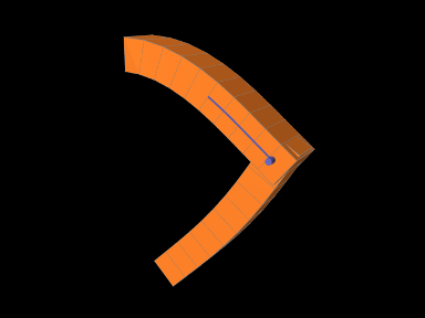
It creates two FEM beams and connects them via a special slotted-revolute joint. The build method is shown below:
Lines 3-16 create a MechModel and populate it with two FEM beams, fem1 and fem2, using an auxiliary method addFem() defined in the model source file. The leftmost nodes of fem1 are set fixed. A SlottedRevoluteJoint is then created to interconnect fem1 and fem2 at a location specified by TDW (lines 19-21). Lines 24-29 set some parameters for the joint, along with various render properties.
To run this example in ArtiSynth, select All demos > tutorial > JointedFemBeams from the Models menu. Running the model will cause it to drop and flex under gravity, as shown in Figure 6.14. Forces can interactively be applied to the beams using the pull tool (see the section “Pull Manipulation” in the ArtiSynth User Interface Guide).
![[LOGO]](data:image/png;base64,iVBORw0KGgoAAAANSUhEUgAAAAsAAAAOCAYAAAD5YeaVAAAAAXNSR0IArs4c6QAAAAZiS0dEAP8A/wD/oL2nkwAAAAlwSFlzAAALEwAACxMBAJqcGAAAAAd0SU1FB9wKExQZLWTEaOUAAAAddEVYdENvbW1lbnQAQ3JlYXRlZCB3aXRoIFRoZSBHSU1Q72QlbgAAAdpJREFUKM9tkL+L2nAARz9fPZNCKFapUn8kyI0e4iRHSR1Kb8ng0lJw6FYHFwv2LwhOpcWxTjeUunYqOmqd6hEoRDhtDWdA8ApRYsSUCDHNt5ul13vz4w0vWCgUnnEc975arX6ORqN3VqtVZbfbTQC4uEHANM3jSqXymFI6yWazP2KxWAXAL9zCUa1Wy2tXVxheKA9YNoR8Pt+aTqe4FVVVvz05O6MBhqUIBGk8Hn8HAOVy+T+XLJfLS4ZhTiRJgqIoVBRFIoric47jPnmeB1mW/9rr9ZpSSn3Lsmir1fJZlqWlUonKsvwWwD8ymc/nXwVBeLjf7xEKhdBut9Hr9WgmkyGEkJwsy5eHG5vN5g0AKIoCAEgkEkin0wQAfN9/cXPdheu6P33fBwB4ngcAcByHJpPJl+fn54mD3Gg0NrquXxeLRQAAwzAYj8cwTZPwPH9/sVg8PXweDAauqqr2cDjEer1GJBLBZDJBs9mE4zjwfZ85lAGg2+06hmGgXq+j3+/DsixYlgVN03a9Xu8jgCNCyIegIAgx13Vfd7vdu+FweG8YRkjXdWy329+dTgeSJD3ieZ7RNO0VAXAPwDEAO5VKndi2fWrb9jWl9Esul6PZbDY9Go1OZ7PZ9z/lyuD3OozU2wAAAABJRU5ErkJggg==)