6.9 Muscle activated FEM models
Finite element muscle models are an extension to regular FEM models. As such, everything previously discussed for regular FEM models also applies to FEM muscles. Muscles have additional properties that allow them to contract when activated. There are two types of muscles supported:
- Fibre-based:
-
Point-to-point muscle fibres are embedded in the model.
- Material-based:
-
An auxiliary material is added to the constitutive law to embed muscle properties.
In this section, both types will be described.
6.9.1 FemMuscleModel
The main class for FEM-based muscles is FemMuscleModel, a subclass of FemModel3d. It differs from a basic FEM model in that it has the new property
| Property | Description |
| muscleMaterial | An object that adds an activation-dependent ‘muscle’ term to the constitutive law. |
This is a delegate object of type MuscleMaterial, described in detail in Section 6.10.3, that computes activation-dependent stress and stiffness in the muscle. In addition to this property, FemMuscleModel adds two new lists of subcomponents:
- bundles
-
Groupings of muscle sub-units (fibres or elements) that can be activated. - exciters
-
Components that control the activation of a set of bundles or other exciters.
6.9.1.1 Bundles
Muscle bundles allow for a muscle to be partitioned into separate groupings of fibres/elements, where each bundle can be activated independently. They are implemented in the class MuscleBundle. Bundles have three key properties:
| Property | Description |
|---|---|
| excitation | Activation level of the muscle, |
| fibresActive | Enable/disable “fibre-based” muscle components. |
| muscleMaterial | An object that adds an activation-dependent ‘muscle’ term to the constitutive law (Section 6.10.3). |
The excitation property controls the level of muscle activation, with zero being no muscle action, and one being fully activated. The fibresActive property is a boolean variable that controls whether or not to treat any contained fibres as point-to-point-like muscles (“fibre-based”). If false, the fibres are ignored. The third property, muscleMaterial, allows for a MuscleMaterial to be specified per bundle. By default, its value is inherited from FemMuscleModel.
6.9.1.2 Exciters
A MuscleExciter component enables you to simultaneously activate a group of “excitation components”. This includes: point-to-point muscles, muscle bundles, muscle fibres, material-based muscle elements, and other muscle exciters. Components that can be excited all implement the ExcitationComponent interface. To add or remove a component to the exciter, use
If a gain factor is specified, the activation is scaled by the gain for that component.
6.9.2 Fibre-based muscles
In fibre-based muscles, a set of point-to-point muscle fibres are added between FEM nodes or markers. Each fibre is assigned an AxialMuscleMaterial, just like for regular point-to-point muscles (Section 4.5.1). Note that these muscle materials typically have a “rest length” property, that will likely need to be adjusted for each fibre. Once the set of fibres are added to a MuscleBundle, they need to be enabled. This is done by setting the fibresActive property of the bundle to true.
Fibres are added to a MuscleBundle using one of the functions:
The latter returns the newly created Muscle fibre. The following code snippet demonstrates how to create a fibre-based MuscleBundle and add it to an FEM muscle.
In these fibre-based muscles, force is only exerted between the anchor points of the fibres; it is a discrete approximation. These models are typically more stable than material-based ones.
6.9.3 Material-based muscles
In material-based muscles, the constitutive law is augmented with additional terms to account for muscle-specific properties. This is a continuous representation within the model.
The basic building block for a material-based muscle bundle is a MuscleElementDesc. This object contains a reference to a FemElement3d, a MuscleMaterial, and either a single direction or set of directions that specify the direction of contraction. If a single direction is specified, then it is assumed the entire element contracts in the same direction. Otherwise, a direction can be specified for each integration point within the element. A null direction signals that there is no muscle at the corresponding point. This allows for a sub-element resolution for muscle definitions. The positions of integration points for a given element can be obtained with:
By default, the MuscleMaterial is inherited from the bundle’s material property. Muscle materials are described in detail in Section 6.10.3 and include GenericMuscle, BlemkerMuscle, and FullBlemkerMuscle. The Blemker-type materials are based on [5].
Elements can be added to a muscle bundle using one of the methods:
The following snippet demonstrates how to create and add a material-based muscle bundle:
6.9.4 Example: toy FEM muscle model
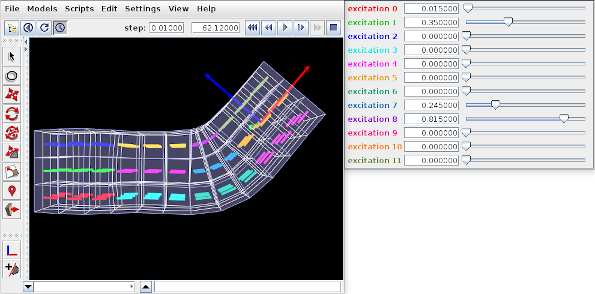
A simple example showing an FEM with material-based muscles is given by artisynth.demos.tutorial.ToyMuscleFem. It consists of a hex-element beam, with 12 muscles added in groups along its length, allowing it to flex in the x-z plane. A frame object is also attached to the right end. The code for the model, without the package and import directives, is listed below:
Within the build() method, the mech model is created in the usual way (lines 8-10). Gravity is turned off to give the muscles greater control over the FEM model’s configuration. The MechModel reference is stored in the class field myMech to enable any subclasses to have easy access to it; the same will be done for the FEM model and the attached frame.
The FEM model itself is created at lines (12-24). An instance of FemMuscleModel is created and then passed to FemFactory.createHexGrid(); this allows the model to be an instance of FemMuscleModel instead of FemModel3d. The model is assigned a linear material with Poisson’s ratio of 0 to allow it to be easily compressed. Muscle bundles will be material-based and will all use the same SimpleForceMuscle material that is assigned to the model’s muscleMaterial property. Density and damping parameters are defined so as to improve model stability when muscles are excited. Once the model is created, its left-hand nodes are fixed to provide anchoring (lines 27-32).
Muscle bundles are created at lines 36-58. There are 12 of them, arranged in three vertical layers and four horizontal sections. Each bundle is populated with 9 adjacent elements in the x-y plane. To find these elements, their center positions are calculated and then passed to the FEM method findNearestVolumetricElement(). The element is then added to the bundle with a resting activation direction parallel to the x axis. For visualization, each bundle’s line color is set to a distinct color from the numeric probe display palette, based on the bundle’s number (lines 53-54).
After the bundles have been added to the FEM model, a control is created to allow interactive control of their excitations (lines 88-95). Each widget is labeled excitation N, where N is the bundle number, and the label is colored to match the bundle’s line color. Finally, a frame is created and attached to the FEM model (lines 59-62), and render properties are set at lines 106-115: Muscle bundles are drawn by showing the activation direction in each element; the frame is displayed as a solid arrow with axis lengths of 0.3; the FEM line and face colors are set to blue-gray, and the surface is rendered and made transparent.
To run this example in ArtiSynth, select All demos > tutorial > ToyMuscleFem from the Models menu. Running the model and adjusting the exciters in the control panel will cause the FEM model to deform in various ways (Figure 6.16).
6.9.5 Example: comparison with two beam examples
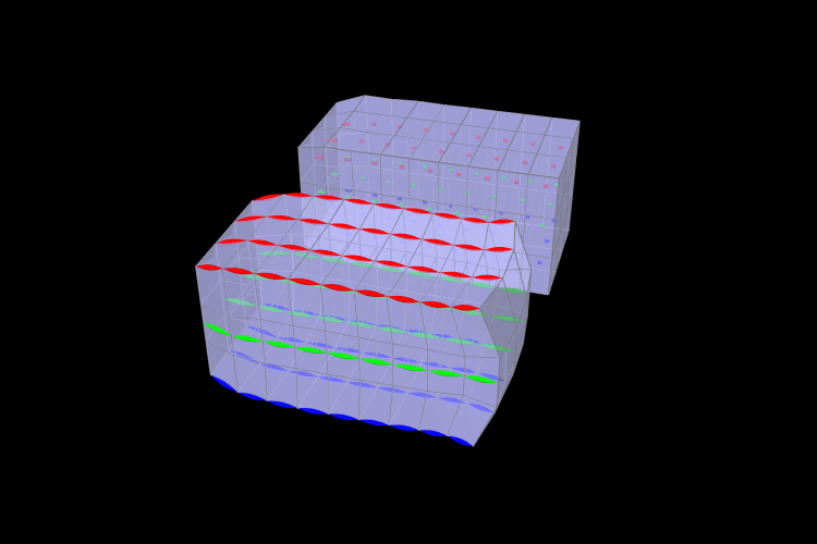
An example comparing a fibre-based and a material-based muscle is shown in Figure 6.17. The code can be found in artisynth.demos.tutorial.FemMuscleBeams. There are two FemMuscleModel beams in the model: one fibre-based, and one material-based. Each has three muscle bundles: one at the top (red), one in the middle (green), and one at the bottom (blue). In the figure, both muscles are fully activated. Note the deformed shape of the beams. In the fibre-based one, since forces only act between point on the fibres, the muscle seems to bulge. In the material-based muscle, the entire continuous volume contracts, leading to a uniform deformation.
Material-based muscles are more realistic. However, this often comes at the cost of stability. The added terms to the constitutive law are highly nonlinear, which may cause numerical issues as elements become highly contracted or highly deformed. Fibre-based muscles are, in general, more stable. However, they can lead to bulging and other deformation artifacts due to their discrete nature.
![[LOGO]](data:image/png;base64,iVBORw0KGgoAAAANSUhEUgAAAAsAAAAOCAYAAAD5YeaVAAAAAXNSR0IArs4c6QAAAAZiS0dEAP8A/wD/oL2nkwAAAAlwSFlzAAALEwAACxMBAJqcGAAAAAd0SU1FB9wKExQZLWTEaOUAAAAddEVYdENvbW1lbnQAQ3JlYXRlZCB3aXRoIFRoZSBHSU1Q72QlbgAAAdpJREFUKM9tkL+L2nAARz9fPZNCKFapUn8kyI0e4iRHSR1Kb8ng0lJw6FYHFwv2LwhOpcWxTjeUunYqOmqd6hEoRDhtDWdA8ApRYsSUCDHNt5ul13vz4w0vWCgUnnEc975arX6ORqN3VqtVZbfbTQC4uEHANM3jSqXymFI6yWazP2KxWAXAL9zCUa1Wy2tXVxheKA9YNoR8Pt+aTqe4FVVVvz05O6MBhqUIBGk8Hn8HAOVy+T+XLJfLS4ZhTiRJgqIoVBRFIoric47jPnmeB1mW/9rr9ZpSSn3Lsmir1fJZlqWlUonKsvwWwD8ymc/nXwVBeLjf7xEKhdBut9Hr9WgmkyGEkJwsy5eHG5vN5g0AKIoCAEgkEkin0wQAfN9/cXPdheu6P33fBwB4ngcAcByHJpPJl+fn54mD3Gg0NrquXxeLRQAAwzAYj8cwTZPwPH9/sVg8PXweDAauqqr2cDjEer1GJBLBZDJBs9mE4zjwfZ85lAGg2+06hmGgXq+j3+/DsixYlgVN03a9Xu8jgCNCyIegIAgx13Vfd7vdu+FweG8YRkjXdWy329+dTgeSJD3ieZ7RNO0VAXAPwDEAO5VKndi2fWrb9jWl9Esul6PZbDY9Go1OZ7PZ9z/lyuD3OozU2wAAAABJRU5ErkJggg==)