9.5 Alternate Wrapping Surfaces
Although it common to use the general mesh geometry of a RigidBody as the wrapping surface, situations may arise where it is desirable to not do this. These may include:
-
•
The general mesh geometry is not sufficiently smooth to form a good wrapping surface;
-
•
Wrapping around the default mesh geometry is not stable, in that it is too easy for the wrap strand to “slip off”;
-
•
Using one of the simpler analytic geometries (Table 9.1) may result in a more efficient computation.
There are a couple of ways to handle this. One, discussed in Section 9.3, involves creating a collision mesh which is separate from the general mesh geometry. However, that same collision mesh must then also be used for collision handling (Chapter 8). If that is undesirable, or if multiple wrapping surfaces are needed, then a different approach may be used. This involves creating the desired wrappable as a separate object and then attaching it to the main RigidBody. Typically, this wrappable will be created with zero mass (or density), so that it does not alter the effective mass or inertia of the main body. The general procedure then becomes:
-
1.
Create the main RigidBody with whatever desired geometry and inertia is needed;
-
2.
Create the additional wrappable object(s), usually with zero density/mass;
-
3.
Attach the wrappables to the main body using one of the MechModel attachFrame() methods described in Section 3.9.3.
9.5.1 Example: wrapping for a finger joint
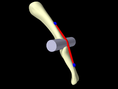
An example using an alternate wrapping surface is given by artisynth.demos.tutorial.PhalanxWrapping, which shows a muscle wrapping around a joint between two finger bones. Because the bones themselves are fairly narrow, using them as wrapping surfaces would likely lead to the muscle slipping off. Instead, a RigidCylinder is used for the wrapping and attached to one of the bones. The code, with include directives excluded, is given below:
The method createBody() (lines 6-14) creates a rigid body from a geometry mesh stored in a file in the directory “data” beneath the source directory, using the utility class PathFinder used to determine the file path (Section 2.6).
Within the build() method, a MechModel is created containing two rigid bodies representing the bones, proximal and distal, with proximal fixed and distal free to move with a frame damping of 0.03 (lines 18-28). A cylindrical joint is then added between the bones, along with markers describing the muscle’s origin and insertion points (lines 31-42). A RigidCylinder is created to act as a wrapping obstacle and attached to the distal bone in the same location as the joint (lines 46-50); since it is created with a density of 0 it has no mass and hence does not affect the bone’s inertia. The muscle itself is created at lines 53-64, using a SimpleAxialMuscle as a material and an extra initial point specified to setSegmentWrappable() to ensure that it wraps around the cylinder in the correct way (Section 9.4). Finally, some render properties are set at lines 67-69.
To run this example in ArtiSynth, select All demos > tutorial > PhalanxWrapping from the Models menu. The model should load and initially appear as in Figure 9.12. When running the model, one can move the distal bone either by using the pull tool (Section “Pull Manipulation” in the ArtiSynth User Interface Guide), or selecting the muscle in the GUI, invoking a property dialog by choosing Edit properties ... from the right-click context menu, and adjusting the excitation property.
9.5.2 Example: toy muscle arm with wrapping
|
|
A more complex example of wrapping, combined with multiple joints and point-to-point muscles, is given by artisynth.demos.tutorial.ToyMuscleArm, which depicts a two-link “arm”, connected by hinge joints, with opposing muscles controlling the poses of each link. The code, with import directives excluded, is given below:
Within the build() method, the mech model is created in the usual way and inertial damping is set to 1.0 (lines 73-75). Next, the rigid bodies depicting the base and links are created (lines 78-93). All bodies are created from meshes, with the base being made non-dynamic and the poses of the links set so that they line up vertically in their start position (Figure 9.13, left). A massless cylinder is created to provide a wrapping surface around the second hinge joint and attached to link1 (lines 96-109).
Hinge joints (Section 3.5.1) are then added between the base and link0 and link0 and link1 (lines 103-104), using the convenience method addHingeJoint() (lines 58-70). This method creates a hinge joint at a prescribed position in the x-z plane, uses it to connect two bodies, sets the range for the joint angle theta, and sets properties to render the shaft in blue.
Next, point-to-point muscles are placed on opposite sides of each link (lines 106-111). For link0, two Muscle components are used, added with the method addMuscle() (lines 18-29); this method creates a muscle connecting two bodies, using frame markers whose positions are specified in world coordinates in the x-z plane, and a SimpleMuscleMaterial (Section 4.5.1.1) with prescribed stiffness and maximum active force. For link1, MultiPointMuscle components are used instead so that they can be wrapped around the wrapping cylinder. These muscles are created with the method addWrappedMuscle() (lines 35-51), which creates a multipoint muscle connecting two bodies, using a single wrappable segment between two frame markers (also specified in the x-z plane). After the muscle is placed, its updateWrapSegments() method is called to “shrink wrap” it around the cylinder.
A marker is attached to the tip on link1 at lines 114-115, and then the links are repositioned, by setting the joint angles, so that the arm is not initially upright and will hence move when first run (lines 119-120). After repositioning, all wrap paths are updated by calling the MechModel method updateWrapSegments() (line 121), and the rest lengths for all muscles are set to their current lengths so that they will not initially exert passive tension (lines 124-127).
A control panel is created to allow runtime adjustment of the four muscle excitation values (lines 130-135), and render properties are set at lines 139-143.
![[LOGO]](data:image/png;base64,iVBORw0KGgoAAAANSUhEUgAAAAsAAAAOCAYAAAD5YeaVAAAAAXNSR0IArs4c6QAAAAZiS0dEAP8A/wD/oL2nkwAAAAlwSFlzAAALEwAACxMBAJqcGAAAAAd0SU1FB9wKExQZLWTEaOUAAAAddEVYdENvbW1lbnQAQ3JlYXRlZCB3aXRoIFRoZSBHSU1Q72QlbgAAAdpJREFUKM9tkL+L2nAARz9fPZNCKFapUn8kyI0e4iRHSR1Kb8ng0lJw6FYHFwv2LwhOpcWxTjeUunYqOmqd6hEoRDhtDWdA8ApRYsSUCDHNt5ul13vz4w0vWCgUnnEc975arX6ORqN3VqtVZbfbTQC4uEHANM3jSqXymFI6yWazP2KxWAXAL9zCUa1Wy2tXVxheKA9YNoR8Pt+aTqe4FVVVvz05O6MBhqUIBGk8Hn8HAOVy+T+XLJfLS4ZhTiRJgqIoVBRFIoric47jPnmeB1mW/9rr9ZpSSn3Lsmir1fJZlqWlUonKsvwWwD8ymc/nXwVBeLjf7xEKhdBut9Hr9WgmkyGEkJwsy5eHG5vN5g0AKIoCAEgkEkin0wQAfN9/cXPdheu6P33fBwB4ngcAcByHJpPJl+fn54mD3Gg0NrquXxeLRQAAwzAYj8cwTZPwPH9/sVg8PXweDAauqqr2cDjEer1GJBLBZDJBs9mE4zjwfZ85lAGg2+06hmGgXq+j3+/DsixYlgVN03a9Xu8jgCNCyIegIAgx13Vfd7vdu+FweG8YRkjXdWy329+dTgeSJD3ieZ7RNO0VAXAPwDEAO5VKndi2fWrb9jWl9Esul6PZbDY9Go1OZ7PZ9z/lyuD3OozU2wAAAABJRU5ErkJggg==)