3.5 Joint components
ArtiSynth supplies a number of basic joints and connectors in the package artisynth.core.mechmodels, the most common of which are described here.
Many of the descriptions are associated with a demonstration model, named XXXJointDemo, where XXX is the joint type. These demos are located in the package artisynth.demos.mech, and can be loaded by selecting All demos > mech > XXXJointDemo from the Models menu. When run, they can be interactively controlled, using either the pull tool (see the section “Pull Manipulation” in the ArtiSynth User Interface Guide), or the interactive control panel. The control panel allows the adjustment of coordinate values and ranges (if supported), some of the render properties, and the different compliance and damping properties (Section 3.4.9). One can inspect the source code for each demo in its .java file located in the folder <ARTISYNTH_HOME>/src/artisynth/demos/mech.
3.5.1 Hinge joint
 |
 |
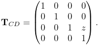
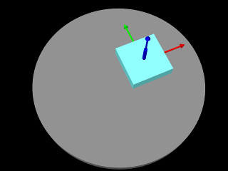
The HingeJoint
(Figure 3.14) is a 1 DOF joint that
constrains motion between frames C and D to a simple rotation about
the ![]() axis of D. It implements six constraints and one coordinate
axis of D. It implements six constraints and one coordinate
![]() (Table 3.1), to which the joint transform
(Table 3.1), to which the joint transform
![]() is related by
is related by
 |
The value and ranges for ![]() are exported by the properties theta and thetaRange, and the
are exported by the properties theta and thetaRange, and the ![]() coordinate index is
defined by the constant THETA_IDX. For rendering, the
properties shaftLength and shaftRadius control the size of
a shaft drawn about the rotation axis, using the faceColor
rendering property. A demo is provided by
coordinate index is
defined by the constant THETA_IDX. For rendering, the
properties shaftLength and shaftRadius control the size of
a shaft drawn about the rotation axis, using the faceColor
rendering property. A demo is provided by
artisynth.demos.mech.HingeJointDemo.
In addition to the standard constructors described in Section 3.4.3,
creates a hinge joint with a specified origin and ![]() axis direction
for frame D (in world coordinates), and frames C and D coincident.
axis direction
for frame D (in world coordinates), and frames C and D coincident.
| Index | type/name | description |
|---|---|---|
| 0 | bilateral | restricts translation along |
| 1 | bilateral | restricts translation along |
| 2 | bilateral | restricts translation along |
| 3 | bilateral | restricts rotation about |
| 4 | bilateral | restricts rotation about |
| 5 | unilateral | enforces limits on |
| 0 | counter-clockwise rotation of |
3.5.2 Slider joint
 |
 |
The SliderJoint
(Figure 3.15) is a 1 DOF joint
that constrains motion between frames C and D to a simple translation
along the ![]() axis of D. It implements six constraints and one
coordinate
axis of D. It implements six constraints and one
coordinate ![]() (Table 3.2), to which the joint
transform
(Table 3.2), to which the joint
transform ![]() is related by
is related by
 |
The value and ranges for ![]() are exported by the properties z
and zRange, and the
are exported by the properties z
and zRange, and the ![]() coordinate index is defined by the
constant Z_IDX. For rendering, the properties shaftLength and shaftRadius control the size of a shaft drawn
about the sliding axis, using the faceColor rendering property.
A demo is provided by artisynth.demos.mech.SliderJointDemo.
coordinate index is defined by the
constant Z_IDX. For rendering, the properties shaftLength and shaftRadius control the size of a shaft drawn
about the sliding axis, using the faceColor rendering property.
A demo is provided by artisynth.demos.mech.SliderJointDemo.
In addition to the standard constructors described in Section 3.4.3,
creates a slider joint with a specified origin and ![]() axis direction
for frame D (in world coordinates), and frames C and D coincident.
axis direction
for frame D (in world coordinates), and frames C and D coincident.
| Index | type/name | description |
|---|---|---|
| 0 | bilateral | restricts translation along |
| 1 | bilateral | restricts translation along |
| 2 | bilateral | restricts rotation about |
| 3 | bilateral | restricts rotation about |
| 4 | bilateral | restricts rotation about |
| 5 | unilateral | enforces limits on the |
| 0 | translation of |
3.5.3 Cylindrical joint
 |
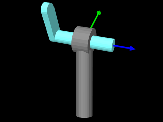 |
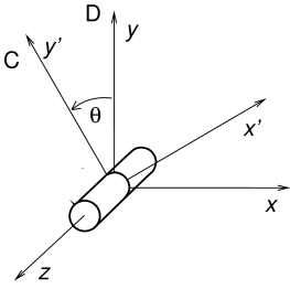
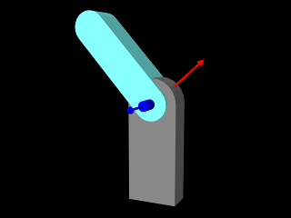
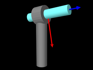
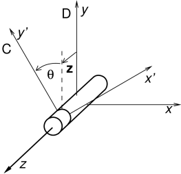
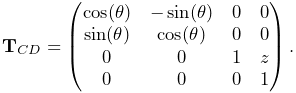
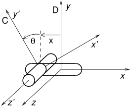
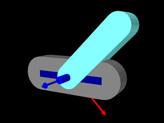
The CylindricalJoint
(Figure 3.16) is a 2 DOF
joint that constrains motion between frames C and D to translation and
rotation along and about the ![]() axis of D. It implements six
constraints and two coordinates
axis of D. It implements six
constraints and two coordinates ![]() and
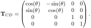
and ![]() (Table 3.3), to which the joint transform
(Table 3.3), to which the joint transform
![]() is related by
is related by
 |
The value and ranges for ![]() and
and ![]() are exported by the
properties z, theta, zRange and thetaRange,
and the coordinate indices are defined by the constants Z_IDX
and THETA_IDX. For rendering, the properties shaftLength
and shaftRadius control the size of a shaft drawn about the
sliding/rotation axis, using the faceColor rendering property.
A demo is provided by artisynth.demos.mech.CylindricalJointDemo.
are exported by the
properties z, theta, zRange and thetaRange,
and the coordinate indices are defined by the constants Z_IDX
and THETA_IDX. For rendering, the properties shaftLength
and shaftRadius control the size of a shaft drawn about the
sliding/rotation axis, using the faceColor rendering property.
A demo is provided by artisynth.demos.mech.CylindricalJointDemo.
In addition to the standard constructors described in Section 3.4.3,
creates a cylindrical joint with a specified origin and ![]() axis direction
for frame D (in world coordinates), and frames C and D coincident.
axis direction
for frame D (in world coordinates), and frames C and D coincident.
| Index | type/name | description |
|---|---|---|
| 0 | bilateral | restricts translation along |
| 1 | bilateral | restricts translation along |
| 2 | bilateral | restricts rotation about |
| 3 | bilateral | restricts rotation about |
| 4 | unilateral | enforces limits on the |
| 5 | unilateral | enforces limits on the |
| 0 | translation of |
|
| 1 | rotation of |
3.5.4 Slotted hinge joint
 |
 |
The SlottedHingeJoint
(Figure 3.17) is
a 2 DOF joint that constrains motion between frames C and D to
translation along the ![]() axis and rotation about the
axis and rotation about the ![]() axis of D.
It implements six constraints and two coordinates
axis of D.
It implements six constraints and two coordinates ![]() and
and ![]() (Table 3.4), to which the joint
transform
(Table 3.4), to which the joint
transform ![]() is related by
is related by
 |
(3.19) |
The value and ranges for ![]() and
and ![]() are exported by the
properties x, theta, xRange and thetaRange,
and the coordinate indices are defined by the constants X_IDX
and THETA_IDX. For rendering, the properties shaftLength
and shaftRadius control the size of a shaft drawn about the
rotation axis, while slotWidth and slotDepth control the
width and depth of a slot drawn along the sliding (
are exported by the
properties x, theta, xRange and thetaRange,
and the coordinate indices are defined by the constants X_IDX
and THETA_IDX. For rendering, the properties shaftLength
and shaftRadius control the size of a shaft drawn about the
rotation axis, while slotWidth and slotDepth control the
width and depth of a slot drawn along the sliding (![]() ) axis; both are
drawn using the faceColor rendering property. When rendering the
slot, its bounds along the
) axis; both are
drawn using the faceColor rendering property. When rendering the
slot, its bounds along the ![]() axis are set to xRange by
default. However, this may be too large, particularly if xRange
is unbounded. As an alternate, the property slotRange will be
used instead if its range (i.e., the upper bound minus the lower
bound) exceeds 0. A demo of SlottedHingeJoint is provided by
artisynth.demos.mech.SlottedHingeJointDemo.
axis are set to xRange by
default. However, this may be too large, particularly if xRange
is unbounded. As an alternate, the property slotRange will be
used instead if its range (i.e., the upper bound minus the lower
bound) exceeds 0. A demo of SlottedHingeJoint is provided by
artisynth.demos.mech.SlottedHingeJointDemo.
In addition to the standard constructors described in Section 3.4.3,
creates a slotted hinge joint with a specified origin and ![]() axis direction
for frame D (in world coordinates), and frames C and D coincident.
axis direction
for frame D (in world coordinates), and frames C and D coincident.
| Index | type/name | description |
|---|---|---|
| 0 | bilateral | restricts translation along |
| 1 | bilateral | restricts translation along |
| 2 | bilateral | restricts rotation about |
| 3 | bilateral | restricts rotation about |
| 4 | unilateral | enforces limits on the |
| 5 | unilateral | enforces limits on the |
| 0 | translation of |
|
| 1 | rotation of |
3.5.5 Universal joint
 |
 |
| Index | type/name | description |
|---|---|---|
| 0 | bilateral | restricts translation along |
| 1 | bilateral | restricts translation along |
| 2 | bilateral | restricts translation along |
| 3 | bilateral | restricts rotation about the final |
| 4 | unilateral | enforces limits on the roll coordinate |
| 5 | unilateral | enforces limits on the pitch coordinate |
| 0 |
|
first rotation of |
| 1 |
|
second rotation of |
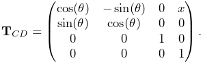
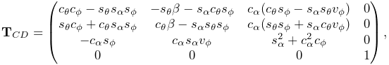
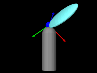
The UniversalJoint
(Figure 3.18) is a 2 DOF joint
that allows C two rotational degrees of freedom with respect to D: a
roll rotation ![]() about D’s
about D’s ![]() axis, followed by a pitch rotation
axis, followed by a pitch rotation ![]() about the rotated
about the rotated ![]() axis. It implements six
constraints and the two coordinates
axis. It implements six
constraints and the two coordinates ![]() and
and ![]() (Table 3.5), to which the joint transform
(Table 3.5), to which the joint transform
![]() is related by
is related by
 |
where
The value and ranges for ![]() and
and ![]() are exported by the
properties roll, pitch, rollRange and pitchRange, and the coordinate indices are defined by the constants
ROLL_IDX and PITCH_IDX.
are exported by the
properties roll, pitch, rollRange and pitchRange, and the coordinate indices are defined by the constants
ROLL_IDX and PITCH_IDX.
For rendering, the properties shaftLength and shaftRadius control the size of shafts drawn about the roll and pitch axes, while jointRadius specifies the radius of a ball drawn around the origin of D; both are drawn using the faceColor rendering property. It is also possible to add a rendering mesh, using the methods:
If present, the rendering mesh is rendered in the intermediate
frame between D and C, i.e., D rotated about ![]() by
by ![]() .
Rendering is controlled by the face rendering properties (
faceStyle, faceColor, etc.).
.
Rendering is controlled by the face rendering properties (
faceStyle, faceColor, etc.).
A demo is provided by artisynth.demos.mech.UniversalJointDemo.
3.5.6 Skewed universal joint
The SkewedUniversalJoint
(Figure 3.19) is a version of the universal
joint in which the pitch axis is skewed relative to its nominal direction
by an angle ![]() . More precisely, let
. More precisely, let ![]() and
and ![]() be the
be the ![]() and
and
![]() axes of C after the initial roll rotation. For a regular universal
joint, the pitch axis is
axes of C after the initial roll rotation. For a regular universal
joint, the pitch axis is ![]() , whereas for a skewed universal joint it
is
, whereas for a skewed universal joint it
is ![]() rotated by
rotated by ![]() clockwise about
clockwise about ![]() . The joint still has
2 DOF, but the space of allowed rotations is reduced.
. The joint still has
2 DOF, but the space of allowed rotations is reduced.
 |
 |
The constraints and the coordinates are the same as for the universal
joint, although the expression for ![]() is now more complicated.
With
is now more complicated.
With ![]() ,
, ![]() ,
, ![]() , and
, and ![]() defined as for the universal
joint,
defined as for the universal
joint, ![]() is given by
is given by
 |
where
Rendering is controlled using the properties shaftLength, shaftRadius and jointRadius in the same way as for the UniversalJoint. A demo is provided by calling artisynth.demos.mech.UniversalJointDemo with the model arguments -skew <angDeg>, where <angDeg> is the desired skew angle in degrees.
Constructors for skewed universal joints take the standard forms described in Section 3.4.3, with an additional argument at the end indicating the skew angle:
In addition, the constructor
creates a skewed universal joint specifying the origin of frame D together with the directions of the roll and pitch axes (in world coordinates). Frames C and D are coincident and the skew angle is inferred from the angle between the axes.
3.5.7 Gimbal joint
 |
 |
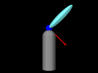
The GimbalJoint
(Figure 3.20) is a 3 DOF spherical joint that anchors
the origins of C and D together but otherwise allows C complete
rotational freedom. The rotational degrees of freedom are
parameterized by three roll-pitch-yaw angles, denoted by
![]() , which define a rotation
, which define a rotation ![]() about D’s
about D’s ![]() axis, followed by a second rotation
axis, followed by a second rotation ![]() about the rotated
about the rotated ![]() axis, followed by a third rotation
axis, followed by a third rotation ![]() about the final
about the final ![]() axis.
It implements six constraints and the three coordinates
axis.
It implements six constraints and the three coordinates
![]() (Table 3.6), to which the
joint transform
(Table 3.6), to which the
joint transform ![]() is related by
is related by
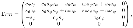 |
where
The value and ranges for ![]() are exported by the
properties roll, pitch, yaw, rollRange, pitchRange, and yawRange, and the coordinate indices are
defined by the constants ROLL_IDX, PITCH_IDX, and YAW_IDX. For rendering, the property jointRadius specifies the
radius of a ball drawn around the origin of D, using the faceColor rendering property. A demo is provided by artisynth.demos.mech.GimbalJointDemo.
are exported by the
properties roll, pitch, yaw, rollRange, pitchRange, and yawRange, and the coordinate indices are
defined by the constants ROLL_IDX, PITCH_IDX, and YAW_IDX. For rendering, the property jointRadius specifies the
radius of a ball drawn around the origin of D, using the faceColor rendering property. A demo is provided by artisynth.demos.mech.GimbalJointDemo.
In addition to the standard constructors described in Section 3.4.3,
creates a gimbal joint with a specified origin for frame D (in world coordinates), and frames C and D coincident and world aligned.
The constraints implementing GimbalJoint are designed so that it is immune to gimbal lock, in which a degree of freedom is lost when
. However, the coordinate values themselves are not immune to this singularity, and neither are the unilateral constraints which enforce limits on their values. Therefore, if coordinate limits are implemented, the joint should be deployed so as to avoid pitch values near
.
| Index | type/name | description |
|---|---|---|
| 0 | bilateral | restricts translation along |
| 1 | bilateral | restricts translation along |
| 2 | bilateral | restricts translation along |
| 3 | unilateral | enforces limits on the roll coordinate |
| 4 | unilateral | enforces limits on the pitch coordinate |
| 5 | unilateral | enforces limits on the yaw coordinate |
| 0 |
|
first rotation of |
| 1 |
|
second rotation of |
| 2 |
|
third rotation of |
3.5.8 Spherical joint
 |
 |
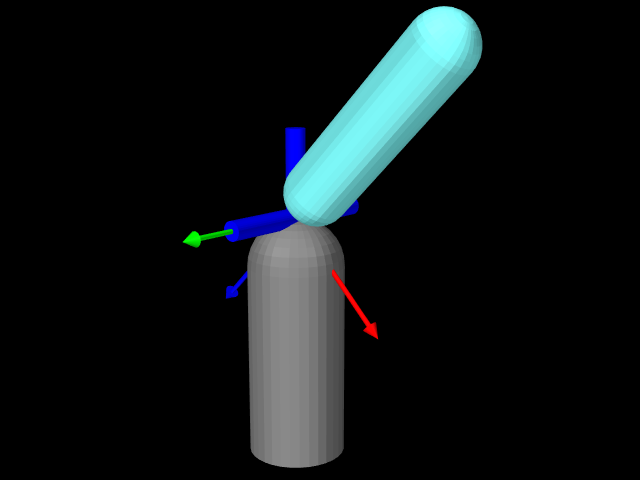
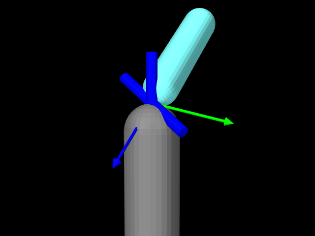
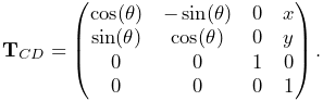
The SphericalJoint (Figure 3.21) is a 3 DOF spherical joint that, like GimbalJoint, anchors the origins of C and D together but otherwise allows C complete rotational freedom. SphericalJoint does not implement any coordinates, and so is conceptually more like a ball joint. However, it does provide two choices for limiting its rotation:
-
•
A limit on the tilt angle
 between
the
between
the  axes of D and C, such that
(3.20) This is intended to emulate the limit imposed by a ball joint socket.
-
•
A limit on the total rotation, defined as follows: Let
 be the axis-angle representation of the rotation matrix of
  ,
normalized such that
,
normalized such that  and
and  , and let
 be a three-vector giving maximum rotation angles with
 ,
,  , and components. Then
  is constrained by
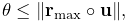
(3.21) where
 denotes the element-wise product. If the components of
are set to a uniform value
denotes the element-wise product. If the components of
are set to a uniform value  , this
simplifies to
, this
simplifies to  .
.
These limits can be enabled by setting the joint’s properties isTiltLimited and isRotationLimited, respectively, where
enabling one disables the other. The limit values ![]() and
and ![]() are managed using the properties maxTilt and
maxRotation, and setting either automatically enables tilt or
rotation limiting, as appropriate. Finally, the tilt angle
are managed using the properties maxTilt and
maxRotation, and setting either automatically enables tilt or
rotation limiting, as appropriate. Finally, the tilt angle ![]() can
be queried using the (read-only) tilt property. For rendering,
the property jointRadius specifies the radius of a ball drawn
around the origin of D, using the faceColor rendering
property. A demo of the SphericalJoint is provided by artisynth.demos.mech.SphericalJointDemo.
can
be queried using the (read-only) tilt property. For rendering,
the property jointRadius specifies the radius of a ball drawn
around the origin of D, using the faceColor rendering
property. A demo of the SphericalJoint is provided by artisynth.demos.mech.SphericalJointDemo.
In addition to the standard constructors described in Section 3.4.3,
creates a spherical joint with a specified origin for frame D (in world coordinates), and frames C and D coincident and world aligned.
One should use the rotation limit with some caution, as the orientations which it prohibits can be somewhat hard to predict, particularly when
| Index | type/name | description |
|---|---|---|
| 0 | bilateral | restricts translation along |
| 1 | bilateral | restricts translation along |
| 2 | bilateral | restricts translation along |
| 3 | unilateral | enforces either the “tilt” or “rotation” limits |
3.5.9 Planar joint
 |
 |
The PlanarJoint
(Figure 3.22) is a 3 DOF
joint that constrains C to translation in the ![]() -
-![]() plane
and rotation about the
plane
and rotation about the ![]() axis of D. It implements six
constraints and three coordinates
axis of D. It implements six
constraints and three coordinates ![]() ,
, ![]() and
and ![]() (Table 3.8), to which the joint transform
(Table 3.8), to which the joint transform
![]() is related by
is related by
 |
The value and ranges for ![]() ,
, ![]() and
and ![]() are exported by the
properties x, y, theta, xRange, yRange
and thetaRange, and the coordinate indices are defined by the
constants X_IDX, Y_IDX and THETA_IDX.
A planar joint can be rendered as a square centered on the origin
of D, using face rendering properties and with a size given by the
planeSize property. For example,
are exported by the
properties x, y, theta, xRange, yRange
and thetaRange, and the coordinate indices are defined by the
constants X_IDX, Y_IDX and THETA_IDX.
A planar joint can be rendered as a square centered on the origin
of D, using face rendering properties and with a size given by the
planeSize property. For example,
will cause joint to be drawn as a light gray square with size 5.0. The default value of planeSize is 0, so drawing the plane is disabled by default. Also, the default faceStyle rendering property for PlanarConnector is set to FRONT_AND_BACK, so that the plane (when drawn) can be seen from both sides. A shaft about the rotation axis can also be drawn, as controlled by the properties shaftLength and shaftRadius and using the faceColor rendering property. A demo is provided by artisynth.demos.mech.PlanarJointDemo.
In addition to the standard constructors described in Section 3.4.3,
creates a planar joint with a specified origin and ![]() axis direction
for frame D (in world coordinates), and frames C and D coincident.
axis direction
for frame D (in world coordinates), and frames C and D coincident.
| Index | type/name | description |
|---|---|---|
| 0 | bilateral | restricts translation along |
| 1 | bilateral | restricts rotation about |
| 2 | bilateral | restricts rotation about |
| 3 | unilateral | enforces limits on the |
| 4 | unilateral | enforces limits on the |
| 5 | unilateral | enforces limits on the |
| 0 | translation of |
|
| 1 | translation of |
|
| 2 | rotation of |
3.5.10 Planar translation joint
 |
| Index | type/name | description |
|---|---|---|
| 0 | bilateral | restricts translation along |
| 1 | bilateral | restricts rotation about |
| 2 | bilateral | restricts rotation about |
| 3 | bilateral | restricts rotation about |
| 4 | unilateral | enforces limits on the |
| 5 | unilateral | enforces limits on the |
| 0 | translation of |
|
| 1 | translation of |
The PlanarTranslationJoint
(Figure 3.23) is a 2 DOF joint
that is the same as the planar joint without rotation:
C is restricted to translation in the ![]() -
-![]() plane of D.
It implements six
constraints and two coordinates
plane of D.
It implements six
constraints and two coordinates ![]() and
and ![]() (Table 3.9), to which the joint transform
(Table 3.9), to which the joint transform
![]() is related by
is related by
 |
The value and ranges for ![]() and
and ![]() are exported by the properties
x, y, xRange and yRange, and the coordinate
indices are defined by the constants X_IDX and Y_IDX. A
planar translation joint can be rendered as a square centered on the
origin of D, using face rendering properties and with a size given by
the planeSize property, in the same way as described for PlanarJoint. A demo is provided by artisynth.demos.mech.PlanarJointDemo.
are exported by the properties
x, y, xRange and yRange, and the coordinate
indices are defined by the constants X_IDX and Y_IDX. A
planar translation joint can be rendered as a square centered on the
origin of D, using face rendering properties and with a size given by
the planeSize property, in the same way as described for PlanarJoint. A demo is provided by artisynth.demos.mech.PlanarJointDemo.
3.5.11 Ellipsoid joint
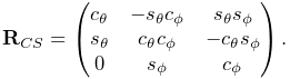
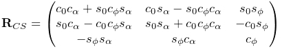
The EllipsoidJoint is a 4 DOF joint that provides similar functionality to the ellipsoidal and scapulothoracic joints available in OpenSim. It allows the origin of C to slide around on the surface of an ellipsoid centered on the origin of D, together with two additional rotational degrees of freedom.
 |
 |
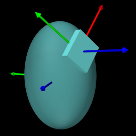 |
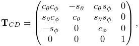
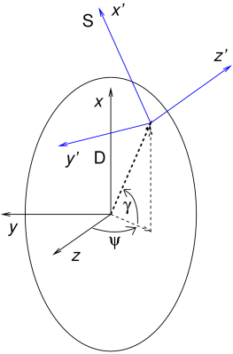
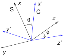
The joint kinematics is easiest to describe in terms of an
intermediate frame S whose origin lies on the ellipsoid surface,
with its position controlled by two coordinates: a longitude
angle ![]() , and a latitude angle
, and a latitude angle ![]() (Figure
3.24, left). Frame C has the same origin as
S, with two additional coordinates,
(Figure
3.24, left). Frame C has the same origin as
S, with two additional coordinates, ![]() and
and ![]() which allow it
to rotate about S (Figure 3.24, middle). If the
transform
which allow it
to rotate about S (Figure 3.24, middle). If the
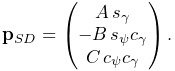
transform ![]() from S to D and the (rotational-only) transform
from S to D and the (rotational-only) transform
![]() from C to S are given by
from C to S are given by
then ![]() is given by
is given by
The six constraints and four coordinates of the ellipsoidal joint are described in table 3.10.
| Index | type/name | description |
| 0 | bilateral | restricts C to the ellipsoid surface and limits rotation |
| 1 | bilateral | restricts C to the ellipsoid surface and limits rotation |
| 2 | unilateral | enforces limits on the |
| 3 | unilateral | enforces limits on the |
| 4 | unilateral | enforces limits on the |
| 5 | unilateral | enforces limits on the |
| 0 | longitude angle for origin of S (and C) on the ellipsoid | |
| 1 | latitude angle for origin of S (and C) on the ellipsoid | |
| 2 | first rotation of C about the |
|
| 3 | second rotation of C about rotated |
For frame S, if ![]() ,
, ![]() and
and ![]() are the ellipsoid semi-axis lengths
for the
are the ellipsoid semi-axis lengths
for the ![]() ,
, ![]() , and
, and ![]() axes, and
axes, and ![]() ,
, ![]() ,
, ![]() ,
and
,
and ![]() are the cosines and sines of
are the cosines and sines of ![]() and
and ![]() , we
can show that
, we
can show that
 |
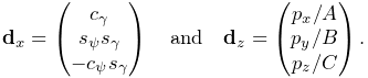
For the orientation of S, the ![]() axis of S is parallel to the surface
normal and the
axis of S is parallel to the surface
normal and the ![]() axis is parallel to the tangent direction imparted
by the latitudinal velocity
axis is parallel to the tangent direction imparted
by the latitudinal velocity ![]() . That means
. That means ![]() and
and ![]() axes are parallel to the direction vectors
axes are parallel to the direction vectors ![]() and
and ![]() given by
given by
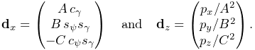 |
(3.22) |
The columns of ![]() are then given by the normalized values
of
are then given by the normalized values
of ![]() ,
, ![]() , and
, and ![]() , respectively.
, respectively.
The rotation ![]() is formed by a rotation
is formed by a rotation ![]() about the
about the ![]() axis, followed by a rotation of
axis, followed by a rotation of ![]() about the new
about the new ![]() axis.
Letting
axis.
Letting ![]() ,
, ![]() ,
, ![]() , and
, and ![]() be the cosines and sines of
be the cosines and sines of
![]() and
and ![]() , we then have
, we then have
 |
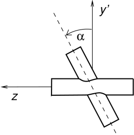
If desired, the ![]() rotation can instead be performed about a
modified axis
rotation can instead be performed about a
modified axis ![]() that makes an angle
that makes an angle ![]() with respect to
with respect to ![]() in the
in the ![]() -
-![]() plane.
plane. ![]() is controlled by the joint’s alpha
property (default value
is controlled by the joint’s alpha
property (default value ![]() ) and corresponds to the “winging” angle
of the OpenSim scapulothoracic joint. If
) and corresponds to the “winging” angle
of the OpenSim scapulothoracic joint. If ![]() ,
,
![]() takes the more complex form
takes the more complex form
 |
where ![]() ,
, ![]() ,
, ![]() , and
, and ![]() are the cosines and sines of
are the cosines and sines of
![]() and
and ![]() , respectively.
, respectively.
Within an EllipsoidJoint, the values and ranges for ![]() ,
,
![]() ,
, ![]() and
and ![]() are exported by the properties longitude, latitude, theta, phi, longitudeRange, latitudeRange, thetaRange, and phiRange, and the coordinate indices are defined by the constants
LONGITUDE_IDX, LATITUDE_IDX, THETA_IDX, and PHI_IDX. For rendering, the property drawEllipsoid specifies
whether the ellipsoid surface should be drawn; if true, it will
be drawn using the joint’s face rendering properties. A demo is
provided by artisynth.demos.mech.EllipsoidJointDemo.
are exported by the properties longitude, latitude, theta, phi, longitudeRange, latitudeRange, thetaRange, and phiRange, and the coordinate indices are defined by the constants
LONGITUDE_IDX, LATITUDE_IDX, THETA_IDX, and PHI_IDX. For rendering, the property drawEllipsoid specifies
whether the ellipsoid surface should be drawn; if true, it will
be drawn using the joint’s face rendering properties. A demo is
provided by artisynth.demos.mech.EllipsoidJointDemo.
Ellipsoid joints can be created with the following constructors:
The first of these creates a joint that is not attached to any
bodies; attachment can be done later using one of the setBodies() methods. Its semi-axis lengths are given by A,
B, and C, its ![]() angle is given by alpha, and
the argument openSimCompatible, if true, makes the joint
kinematics compatible with OpenSim (Section 3.5.11.1).
The second constructor creates a joint and then attaches it to rigid
bodies rbodyA and rbodyB, with the specified
angle is given by alpha, and
the argument openSimCompatible, if true, makes the joint
kinematics compatible with OpenSim (Section 3.5.11.1).
The second constructor creates a joint and then attaches it to rigid
bodies rbodyA and rbodyB, with the specified ![]() and
and
![]() transformations. The third constructor creates a joint and
attaches it to connectable bodies cbodyA and cbodyB, with
the locations of the C and D frames specified in world coordinates by
TCW and TDW.
transformations. The third constructor creates a joint and
attaches it to connectable bodies cbodyA and cbodyB, with
the locations of the C and D frames specified in world coordinates by
TCW and TDW.
Unlike in many joints,
. That is because the origin of C must lie on the ellipsoid surface, and since D is at the center of the ellipsoid,
but
.
3.5.11.1 OpenSim compatibility
The openSimCompatible argument in some of the joint’s
constructors makes the kinematics compatible with the ellipsoidal
joint used by OpenSim. This means that ![]() is computed
differently: in OpenSim, instead of
using (3.22), the
is computed
differently: in OpenSim, instead of
using (3.22), the ![]() and
and ![]() axis directions of
axis directions of
![]() are computed using
are computed using
 |
(3.23) |
In particular, this means that the ![]() axis is only approximately
parallel to the ellipsoid surface normal.
axis is only approximately
parallel to the ellipsoid surface normal.
In OpenSim, the axes of the C frame of both the ellipsoid and scapulothoracic joints are oriented differently than those of the ArtiSynth joint: they are rotated by
about
and
3.5.12 Solid joint
The SolidJoint
is a 0 DOF joint that rigidly constrains C to D. It
implements six constraints and no coordinates
(Table 3.11) and the resulting ![]() is the
identity.
is the
identity.
There aren’t normally many uses for solid joints. If one wishes to create a complex rigid body by joining together a variety of shapes, this can be done more efficiently by making these shapes mesh components of a single rigid body (Section 3.2.9).
| Index | type/name | description |
|---|---|---|
| 0 | bilateral | restricts translation along |
| 1 | bilateral | restricts translation along |
| 2 | bilateral | restricts translation along |
| 3 | bilateral | restricts rotation about |
| 4 | bilateral | restricts rotation about |
| 5 | bilateral | restricts rotation about |
3.5.13 Planar Connector
 |
| Index | type/name | description |
|---|---|---|
| 0 | bilateral or unilateral | restricts translation along |
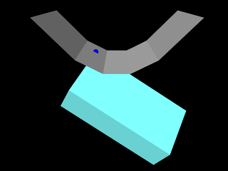
The PlanarConnector
(Figure 3.25) is a 5 DOF connector that attaches
the origin of C to the ![]() -
-![]() plane of D. C is completely free to
rotate, and to translate within the
plane of D. C is completely free to
rotate, and to translate within the ![]() -
-![]() plane. Only motion in the
plane. Only motion in the
![]() direction is restricted. PlanarConnector implements one
constraint and has no coordinates
(Table 3.12).
direction is restricted. PlanarConnector implements one
constraint and has no coordinates
(Table 3.12).
A PlanarConnector constrains a point on body A (located at the
origin of C) to move within a plane on body B. Several planar
connectors can be employed to constrain body motions in more
complicated ways, although one must be careful to avoid
overconstraining the system. The connector can also be configured to
function unilaterally, via its unilateral property, in
which case the point is constrained to lie in the half-space defined by
![]() with respect to D. Several unilateral PlanarConnectors
can therefore be used to implement a cheap and approximate collision
mechanism with fixed collision points.
with respect to D. Several unilateral PlanarConnectors
can therefore be used to implement a cheap and approximate collision
mechanism with fixed collision points.
When set to function unilaterally, overconstraining the system is not an issue because of the way in which ArtiSynth solves unilateral constraints.
A planar connector can be rendered as a square centered on the origin of D, using face rendering properties and with a size given by the planeSize property. The point attached to A can also be rendered using point rendering properties. For example,
will cause connector to be drawn as a light gray square with size 5, and for the point on body A to be drawn as a blue sphere with radius 0.1. The default value of planeSize is 0, so drawing the plane is disabled by default. Also, the default faceStyle rendering property for PlanarConnector is set to FRONT_AND_BACK, so that the plane (when drawn) can be seen from both sides.
Constructors for the PlanarConnector include
where pCA gives the connection point of body A with respect to frame A, TDB gives the transform from frame D to frame B, and TDW gives the transform from frame D to world.
3.5.14 Segmented Planar Connector
 |
 |
| Index | type/name | description |
|---|---|---|
| 0 | bilateral or unilateral | restricts translation normal to the surface |
The SegmentedPlanarConnector
(Figure 3.26) is a 5 DOF connector that
generalizes PlanarConnector to a piecewise linear surface, to
which the origin of ![]() is constrained while
is constrained while ![]() is otherwise
completely free to rotate. The surface is specified by a sequence of
2D points defining a piecewise linear curve in the
is otherwise
completely free to rotate. The surface is specified by a sequence of
2D points defining a piecewise linear curve in the ![]() -
-![]() plane of D
(Figure 3.26, left). This curve does not
need to be a function; the segment nearest to C is the one used to
enforce the constraint at any given time. The surface has infinite
extent and is extrapolated beyond the first and last segments. It
implements one constraint and has no coordinates (Table
3.13).
plane of D
(Figure 3.26, left). This curve does not
need to be a function; the segment nearest to C is the one used to
enforce the constraint at any given time. The surface has infinite
extent and is extrapolated beyond the first and last segments. It
implements one constraint and has no coordinates (Table
3.13).
By appropriate choice of segments, a SegmentedPlanarConnector
can approximate any surface defined by a curve in the ![]() -
-![]() plane.
As with PlanarConnector, it can also be configured as
unilateral, constraining the origin of
plane.
As with PlanarConnector, it can also be configured as
unilateral, constraining the origin of ![]() to lie on the side of the
surface defined by the normal vectors
to lie on the side of the
surface defined by the normal vectors ![]() of each segment
of each segment ![]() . If
. If
![]() and
and ![]() are the points in the
are the points in the ![]() -
-![]() plane defining the
plane defining the
![]() -th segment, and
-th segment, and ![]() is the
is the ![]() axis unit vector, then
axis unit vector, then ![]() is given by
is given by
| (3.24) |
The properties controlling the rendering of a segmented planar
connector are the same as for a planar connector, with each of the
individual plane segments drawn as a rectangle whose length along the
![]() axis is controlled by planeSize.
axis is controlled by planeSize.
Constructors for a SegmentedPlanarConnector are analogous to those used for PlanarConnector,
where segs is an additional argument of type double[]
giving the 2D coordinates defining the segments in the ![]() -
-![]() plane.
plane.
3.5.15 Legacy Joints
ArtiSynth maintains three legacy joints for compatibility with earlier software:
-
•
RevoluteJoint is identical to the HingeJoint, except that its coordinate
is oriented clockwise about the axis
instead of counter-clockwise. Rendering is also done
differently, with shafts about the rotation axis drawn using
line rendering properties. -
•
RollPitchJoint is identical to the UniversalJoint, except that its roll-pitch coordinates
 are computed with
respect to the rotation
are computed with
respect to the rotation  from frame D to C, instead of the
rotation
from frame D to C, instead of the
rotation  from frame C to D. Rendering is also done
differently, with shafts along the roll and pitch axes drawn
using line rendering properties, and the ball around the
origin of D drawn using point rendering properties.
from frame C to D. Rendering is also done
differently, with shafts along the roll and pitch axes drawn
using line rendering properties, and the ball around the
origin of D drawn using point rendering properties. -
•
SphericalRpyJoint is identical to the GimbalJoint, except that its roll-pitch-yaw coordinates
 are computed with
respect to the rotation from frame D to C, instead of the
rotation from frame C to D. Rendering is also done
differently, with the ball around the origin of D drawn using point
rendering properties.
are computed with
respect to the rotation from frame D to C, instead of the
rotation from frame C to D. Rendering is also done
differently, with the ball around the origin of D drawn using point
rendering properties.
3.5.16 Example: A multijointed arm
 |
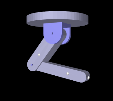 |
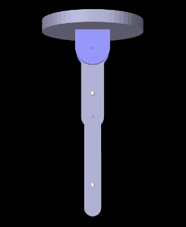
The example model
artisynth.demos.tutorial.MultiJointedArm
shows two links connected by universal and hinge joints to form a 3 DOF robot-like arm. The model class definition, excluding the import directives, is shown here:
Line 3 uses getSourceRelativePath() to locate the geometry folder
relative to the model’s source folder and lines 4-5 define some constants. The
build() method begins by creating and adding a MechModel,
specifying a standard inertial damping of 1, as well as a rotary damping value
to reduce spinning of the first joint about the ![]() axis. The class member
variable myMech is used to store a reference to the MechModel so
that it is available to subclasses.
axis. The class member
variable myMech is used to store a reference to the MechModel so
that it is available to subclasses.
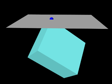
A FixedMeshBody is used to illustrate a mounting plate (lines 15-21);
this is purely decorative and has no dynamic purpose. The links and joints are
then created and assembled in the configuration shown in
Figure 3.27 (left). The first link, link0, is
created from a rounded-box mesh, and then repositioned to align vertically
along the ![]() axis under the mounting plate (lines 23-31). The link is then
attached to ground, just below the mounting plate, using a 2 DOF universal
joint (lines 33-42), with a rendering mesh added to illustrate a mounting
bracket and a range limit of
axis under the mounting plate (lines 23-31). The link is then
attached to ground, just below the mounting plate, using a 2 DOF universal
joint (lines 33-42), with a rendering mesh added to illustrate a mounting
bracket and a range limit of ![]() set on the roll angle. (Note that
similar physics could be achieved with two hinge joints and an additional
link.) The second link, link1, is then also created from a rounded-box
mesh and repositioned vertically along the
set on the roll angle. (Note that
similar physics could be achieved with two hinge joints and an additional
link.) The second link, link1, is then also created from a rounded-box
mesh and repositioned vertically along the ![]() axis under link0 (lines
41-52), to which it is attached using a hinge joint (lines 54-60).
axis under link0 (lines
41-52), to which it is attached using a hinge joint (lines 54-60).
After the linkage has been assembled, some marker points are added to the links (lines 62-67), and the linkage is repositioned by setting some of the joint coordinates (lines 70-72) to assume the configuration shown in Figure 3.27 (right). Finally, some additional render properties are set (lines 73-78).
To run this example in ArtiSynth, select All demos > tutorial > MultiJointedArm from the Models menu. The model should load and initially appear as in Figure 3.27. Running the model will cause the links to fall under gravity. Forces can also be interactively applied using the pull tool (see the section “Pull Manipulation” in the ArtiSynth User Interface Guide).
![[LOGO]](data:image/png;base64,iVBORw0KGgoAAAANSUhEUgAAAAsAAAAOCAYAAAD5YeaVAAAAAXNSR0IArs4c6QAAAAZiS0dEAP8A/wD/oL2nkwAAAAlwSFlzAAALEwAACxMBAJqcGAAAAAd0SU1FB9wKExQZLWTEaOUAAAAddEVYdENvbW1lbnQAQ3JlYXRlZCB3aXRoIFRoZSBHSU1Q72QlbgAAAdpJREFUKM9tkL+L2nAARz9fPZNCKFapUn8kyI0e4iRHSR1Kb8ng0lJw6FYHFwv2LwhOpcWxTjeUunYqOmqd6hEoRDhtDWdA8ApRYsSUCDHNt5ul13vz4w0vWCgUnnEc975arX6ORqN3VqtVZbfbTQC4uEHANM3jSqXymFI6yWazP2KxWAXAL9zCUa1Wy2tXVxheKA9YNoR8Pt+aTqe4FVVVvz05O6MBhqUIBGk8Hn8HAOVy+T+XLJfLS4ZhTiRJgqIoVBRFIoric47jPnmeB1mW/9rr9ZpSSn3Lsmir1fJZlqWlUonKsvwWwD8ymc/nXwVBeLjf7xEKhdBut9Hr9WgmkyGEkJwsy5eHG5vN5g0AKIoCAEgkEkin0wQAfN9/cXPdheu6P33fBwB4ngcAcByHJpPJl+fn54mD3Gg0NrquXxeLRQAAwzAYj8cwTZPwPH9/sVg8PXweDAauqqr2cDjEer1GJBLBZDJBs9mE4zjwfZ85lAGg2+06hmGgXq+j3+/DsixYlgVN03a9Xu8jgCNCyIegIAgx13Vfd7vdu+FweG8YRkjXdWy329+dTgeSJD3ieZ7RNO0VAXAPwDEAO5VKndi2fWrb9jWl9Esul6PZbDY9Go1OZ7PZ9z/lyuD3OozU2wAAAABJRU5ErkJggg==)