8.5 Contact rendering
As mentioned in Section 8.2.1, additional collision behavior properties exist to enable and control the rendering of contact artifacts. These include intersection contours, contact points and normals, contact forces and pressures, and penetration depths. The properties that control these are supplemented by generic render properties (Section 4.3) to specify colors, line widths, etc.
By default, contact rendering is disabled. To enable it, one must set the collision manager to be visible, which can be done using a code fragment like the following:
RenderProps.setVisible (mechModel.getCollisionManager(), true);
CollisionManager and CollisionBehavior both export contact rendering properties. Setting these in the former controls rendering globally for all collisions, while setting them in the latter controls rendering for the collidable pair associated with the behavior. Some artifacts, like contact normals, forces, and color maps, must be drawn with respect to either the first or second collidable. By default, the first collidable is chosen, but the second collidable can be requested using the renderingCollidable property described below. Normals are drawn toward, and forces drawn such that they are acting on, the indicated collidable. For collision behaviors specified using the setCollisionBehavior() methods, the first and second collidables correspond to the collidable0 and collidable1 arguments. Otherwise, for default collision behaviors, the first collidable will be the one whose collidable bodies have the lowest collidable index (Section 8.3.4).
Properties exported by both CollisionManager and CollisionBehavior include:
- renderingCollidable
-
Integer value of either 0 or 1 specifying the collidable for which forces, normals and color maps should be drawn. 0 or 1 selects either the first or second collidable. The default value is 0.
- drawIntersectionContours
-
Boolean value requesting drawing of the intersection contours between collidable meshes, using the generic render properties edgeWidth and edgeColor. The default value is false.
- drawIntersectionPoints
-
Boolean value requesting drawing of the interpenetrating vertices on each collidable mesh, using the generic render properties pointStyle, pointSize, pointRadius, and pointColor. The default value is false.
- drawContactNormals
-
Boolean value requesting drawing of the normals associated with each contact constraint, using the generic render properties lineStyle, lineRadius, lineWidth, and lineColor. The default value is false. The length of the normals is controlled by the contactNormalLen property of the collision manager, which will be set to an appropriate default value if not set explicitly.
- drawContactForces
-
Boolean value requesting drawing of the forces associated with each contact constraint, using the generic render properties lineStyle, lineRadius, edgeWidth, and edgeColor (or lineColor if edgeColor is null). The default value is false. The forces are drawn as line segments starting at each contact point and running parallel to the contact normal, with a length given by the current contact impulse value multiplied by the contactForceLenScale property of the collision manager (which has a default value of 1). The reason for using edgeWidth and edgeColor instead of lineWidth and lineColor is to allow the application to set the render properties such that both normals and forces can be visible if both are being rendered at the same time.
- drawFrictionForces
-
Boolean value requesting the drawing of the forces associated with each contact’s friction force, in the same manner and style as for drawContactForces. The default value is false. Note that unlike contact forces, friction forces are perpendicular to the contact normal.
- drawColorMap
-
An enum of type CollisionBehavior.ColorMapType requesting that a color map be drawn over the contact regions showing a scalar value such as penetration depth or contact force pressure. The collidable (0 or 1) onto which the color map is drawn is controlled by the renderingCollidable property (described below). The range of values used for generating the map is controlled by the colorMapRange property of either the collision manager or the behavior, as described below. The values are mapped onto colors using the colorMap property of the collision manager.
Values of CollisionBehavior.ColorMapType include:
- NONE
-
The color map is disabled. This is the default value.
- PENETRATION_DEPTH
-
The color map shows penetration depth of one collidable mesh with respect to the other. If one or both collidable meshes are open, then the colliderType should be set to AJL_CONTOUR (Section 8.2.1).
- CONTACT_PRESSURE
-
The color map shows the contact pressures over the contact region. Contact pressures are determined by examining the forces at the contact constraints and then distributing these over the surrounding faces. This information is most useful and accurate when using vertex penetration contact (Section 8.4.1.2).
The color map itself is drawn as a patch formed from the collidable’s collision mesh, using faces and vertices associated with the collision region. The vertices of the patch are set to colors corresponding to the associated value (e.g., penetration depth or pressure) at that vertex, and the surrounding faces are colored appropriately. The resolution of the color map is thus determined by the resolution of the collision mesh, and so the application must ensure this is high enough to ensure proper results. If the mesh has only a few triangles (e.g., a rectangle with two triangles per face), the color interpolation may be spread over an unreasonably large area. Examples of color map usage are given in Sections 8.5.2 and 8.5.3.
- colorMapRange
-
Composite property of the type ScalarRange that controls the range of values used for color map rendering. Subproperties include interval, which gives the value range itself, and updating, which specifies how this interval should be updated: FIXED (no updating), AUTO_EXPAND (interval is expanded as values increase or decrease), and AUTO_FIT (interval is reset to fit the values at every render step).
When the colorMapRange value for a CollisionBehavior is set to null (which is the default), the colorMapRange of the CollisionManager is used instead. This has the advantage of ensuring that the same color map range will be used across all collision interactions.
- colorMapInterpolation
-
An enum of type Renderer.ColorInterpolation that explicitly specifies how colors in any rendered color map should be interpolated. RGB and HSV (the default) specify interpolation in RGB and HSV space, respectively. HSV interpolation is the default as it is generally better suited to rendering maps that are purely color-based.
In addition, the following properties are exported by the collision manager:
- contactNormalLen
-
Double value specifying the length with which contact normals should be drawn when drawContactNormals is true. If unspecified, a default value is calculated by the system.
- contactForceLenScale
-
Double value specifying the scaling factor for contact or friction force vectors when they are drawn in response to drawContactForces or drawFrictionForces being true. The default value is 0.
- colorMap
-
Composite property of type ColorMapBase specifying the actual color map used for color map rendering. The default value is HueColorMap.
Generic render properties within the collision manager can be set in the same way as the visibility, using the RenderProps methods presented in Section 4.3.2:
As mentioned above, generic render properties can also be set individually for specific behaviors. This can be done using code fragments like this:
To access these properties on a read-only basis, one can do
Because of the manner in which ArtiSynth handles contacts, rendered contact information may sometimes appear to lag the simulation by one time step. That is because contacts are computed at the end of each time step
, and then used to compute the contact forces during the next step
. The contact information displayed at the end of step
, along with contact forces that are computed during step
8.5.1 Example: rendering normals and contours
A simple model illustrating contact rendering is defined in
artisynth.demos.tutorial.BallPlateCollide
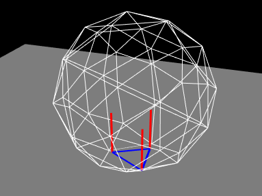
This shows a ball colliding with a plate, while rendering the resulting contact normals in red and the intersection contours in blue. This demo also allows the user to experiment with compliant contact (Section 8.7.1) by setting compliance and damping properties in a control panel.
The complete source code is shown below:
The build() method starts by creating and adding a MechModel in the usual way (lines 19-20). The ball and plate are both created as rigid bodies (lines 22-28), with the ball pose set so that its origin is above the plate at (0, 0, 2) and its orientation is perturbed so that it will not land on the plate symmetrically (line 24). Collisions between the ball and plate are enabled at line 31, with a friction coefficient of 0.2. To allow better visualization of the contacts, the ball is made transparent by disabling the drawing of faces, and instead enabling the drawing of edges in white with no shading (lines 33-37).
Rendering of contacts and normals is established by setting the render properties of the collision manager (lines 39-47). First, the collision manager is set visible (which it is not by default). Then lines (used to render the contact normals) and edges (used to render to intersection contour) are set to red and blue, each with a pixel width of 3. Drawing of the normals and contour is enabled at lines 46-47.
Lastly, for interactively controlling contact compliance (Section 8.7.1), a control panel is built to allow users to adjust the collision manager’s compliance and damping properties (lines 49-53).
To run this example in ArtiSynth, select All demos > tutorial > BallPlateCollide from the Models menu. When run, the ball will collide with the plate and the contact normals and collision contours will be drawn as shown in Figure 8.14.
To enable compliant contact, set the compliance to a
non-zero value. A value of 0.001 (which corresponds to a contact
stiffness of 1000) causes the ball to bounce considerably when it
lands. To counteract this bouncing, the damping should be set to
a non-zero value. Since the ball has a mass of 0.21, formula
(8.2) suggests that critical damping (for which
![]() ) can be achieved with
) can be achieved with ![]() . This does in fact stop
the bouncing. Increasing the compliance to 0.01 results in the ball
penetrating the plate by a noticeable amount.
. This does in fact stop
the bouncing. Increasing the compliance to 0.01 results in the ball
penetrating the plate by a noticeable amount.
8.5.2 Example: rendering a color map
As described above, it is possible to use the drawColorMap property of the collision behavior to render a color map over the contact area showing a scalar value such as penetration depth or contact pressure. A simple example of this is defined in
artisynth.demos.tutorial.PenetrationRender
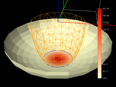
which sets drawColorMap to PENETRATION_DEPTH in order to display the penetration depth of one hemispherical mesh with respect to another.
As mentioned above, proper results require that the collision mesh for the collidable on which the map is being drawn has a sufficiently high resolution.
The complete source code is shown below:
To improve visibility, the example uses two rigid bodies, each created from an open hemispherical mesh using the method createHemiBody() (lines 32-47). Because this example is strictly graphical, the bodies are set to be non-dynamic so that they can be moved around using the viewer’s graphical dragger fixtures (see the section “Transformer Tools” in the ArtiSynth User Interface Guide). Rendering properties for each body are set at lines 67-68 and 73-76, with the top body being rendered as a wireframe to improve visibility.
Lines 80-84 create and set a collision behavior between the two bodies with the drawColorMap property set to PENETRATION_DEPTH. Because for this example we want to show only the penetration and don’t want a collision response, we set the contact method to be Method.INACTIVE. At line 88, the collider type used by the collision manager is set to ColliderType.AJL_CONTOUR, since this provides more reliable penetration calculations for open meshes. Other rendering properties are set for the collision manager at lines 90-107, including a custom color map that varies between CREAM (the color of the mesh) for no penetration and dark red for maximum penetration. The updating of the color map range in the collision manager is set to AUTO_FIT so that it will be recomputed at every time step. (Since the collision manager’s color map range is set to “auto fit” by default, this is shown for illustrative purposes only. It is also possible to override the collision manager’s color map range by setting the colorMapRange property in specific collision behaviors.)
At line 111, a color bar is created and added to the scene, using the method createColorBar() (lines 50-59), to explicitly show the depth that corresponds to the different colors. The color bar is given the same color map that is used to render the depth. Since the depth range is updated every time step, it is also necessary to update the corresponding labels in the color bar. This is done by overriding the root model’s prerender() method (lines 115-132), where we obtain the color map range for the collision manager and use it to update the color bar labels. (Note that super.prerender(list) is called first, since the color map ranges are updated there.) References to the color bar, MechModel, and bodies are obtained using the CompositeComponent methods get() and findComponent(). This is more robust than storing these references in member variables, since the latter would be lost if the model is saved to and reloaded from a file.
To run this example in ArtiSynth, select All demos > tutorial > PenetrationRender from the Models menu. When run, the meshes will collide and render the penetration depth of the bottom mesh, as shown in Figure 8.15.
When defining the color map for rendering (lines 99-108 in the example), it is recommended that the color corresponding to zero be set to the face color of the collidable mesh. This will allow the color map to blend properly to the regular mesh color.
8.5.3 Example: rendering contact pressures
Color map rendering can also be used to render contact pressures, which can be particularly useful for FEM models. A simple example is defined in
artisynth.demos.tutorial.ContactPressureRender
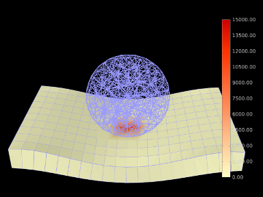
which sets the drawColorMap property of the collision behavior to CONTACT_PRESSURE in order to display a color map of the contact pressure. The example is similar to that of Section 8.5.2, which shows how to render penetration depth.
The caveats about color map rendering described in Section 8.5 apply. Pressure rendering is most useful and accurate when using vertex penetration contact. The resolution of the color map is limited by the resolution of the collision mesh for the collidable on which the map is drawn, and so the application should ensure that this is sufficiently fine. Also, to allow the map to blend properly with the rest of the collidable, the color corresponding to zero pressure should match the default face color for the collidable.
The complete source code is shown below:
To begin, the demo creates two FEM models: a spherical ball (lines 52-56) and a rectangular sheet (lines 59-66), and then fixes the end nodes of the sheet (lines 69-74). Surface rendering is enabled for the sheet (line 65), but not for the ball, in order to improve the visibility of the color map.
Lines 77-81 create and set a collision behavior between the two
models, with the drawColorMap property set to CONTACT_PRESSURE. Because for this example we want the color map to
be drawn on the second collidable (the sheet), we set the renderingCollidable property to 1 (line 79); otherwise, the default
value of 0 would cause the color map to be drawn on the first
collidable (the ball). (Alternatively, we could have simply defined
the collision behavior as being between the surface and the ball
instead of the ball and the sheet.) The color map range is explicitly
set to lie between ![]() (line 80); this is in contrast to the
example in Section 8.5.2, where the range is
auto-updated on each step. The color range is also set explicitly in
the behavior, but if multiple objects were colliding it would likely
be preferable to set it in the collision manager (with the behavior’s
value left as null) to ensure a uniform render range across all
collisions. Other rendering properties are set for the collision
manager at lines 83-97, including a custom color map that varies
between CREAM (the color of the mesh) for no pressure and dark
red for maximum pressure.
(line 80); this is in contrast to the
example in Section 8.5.2, where the range is
auto-updated on each step. The color range is also set explicitly in
the behavior, but if multiple objects were colliding it would likely
be preferable to set it in the collision manager (with the behavior’s
value left as null) to ensure a uniform render range across all
collisions. Other rendering properties are set for the collision
manager at lines 83-97, including a custom color map that varies
between CREAM (the color of the mesh) for no pressure and dark
red for maximum pressure.
At line 100, a color bar is created and added to the scene, using the method createColorBar() (lines 36-45), to explicitly show the pressure that corresponds to the different colors. The color bar is given the same color map and value range used to render the pressure. Finally, default face and line colors for all components in the model are set at lines 105-106.
To run this example in ArtiSynth, select All demos > tutorial > ContactPressureRender from the Models menu. When run, the FEM models will collide and render the contact pressure on the sheet, as shown in Figure 8.16.
![[LOGO]](data:image/png;base64,iVBORw0KGgoAAAANSUhEUgAAAAsAAAAOCAYAAAD5YeaVAAAAAXNSR0IArs4c6QAAAAZiS0dEAP8A/wD/oL2nkwAAAAlwSFlzAAALEwAACxMBAJqcGAAAAAd0SU1FB9wKExQZLWTEaOUAAAAddEVYdENvbW1lbnQAQ3JlYXRlZCB3aXRoIFRoZSBHSU1Q72QlbgAAAdpJREFUKM9tkL+L2nAARz9fPZNCKFapUn8kyI0e4iRHSR1Kb8ng0lJw6FYHFwv2LwhOpcWxTjeUunYqOmqd6hEoRDhtDWdA8ApRYsSUCDHNt5ul13vz4w0vWCgUnnEc975arX6ORqN3VqtVZbfbTQC4uEHANM3jSqXymFI6yWazP2KxWAXAL9zCUa1Wy2tXVxheKA9YNoR8Pt+aTqe4FVVVvz05O6MBhqUIBGk8Hn8HAOVy+T+XLJfLS4ZhTiRJgqIoVBRFIoric47jPnmeB1mW/9rr9ZpSSn3Lsmir1fJZlqWlUonKsvwWwD8ymc/nXwVBeLjf7xEKhdBut9Hr9WgmkyGEkJwsy5eHG5vN5g0AKIoCAEgkEkin0wQAfN9/cXPdheu6P33fBwB4ngcAcByHJpPJl+fn54mD3Gg0NrquXxeLRQAAwzAYj8cwTZPwPH9/sVg8PXweDAauqqr2cDjEer1GJBLBZDJBs9mE4zjwfZ85lAGg2+06hmGgXq+j3+/DsixYlgVN03a9Xu8jgCNCyIegIAgx13Vfd7vdu+FweG8YRkjXdWy329+dTgeSJD3ieZ7RNO0VAXAPwDEAO5VKndi2fWrb9jWl9Esul6PZbDY9Go1OZ7PZ9z/lyuD3OozU2wAAAABJRU5ErkJggg==)