ArtiSynth Update Log
Jun 29, 2026
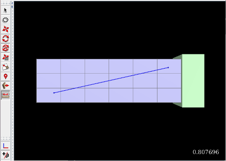
Measurement tool
A new measurement tool has been added to the GUI toolbar, allowing users to interactively measure the distance between two locations selected in the viewer. Selectable locations include points, frames, and any point on a surface mesh. The tool is described in the section “Measurement tool” of the ArtiSynth User Interface Guide.
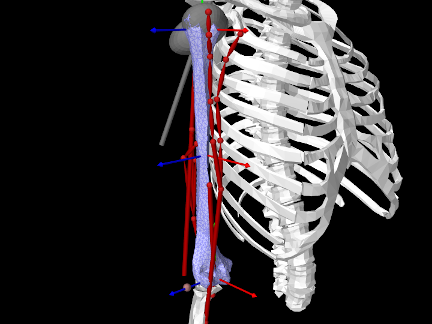
Attached frame components
New components FrameAttachedFrame and FemAttachedFrame have been added, providing a coordinate frame that is attached to, and moves with, a master Frame (or rigid body) or FemModel3d. These are the frame-based analogue of markers, and are described in the new sections “Attached frames” of the “Mechanical Models I” and “Finite Element Models” chapters of the Modeling Guide.

Joint and point actuators
Several new actuator components have been added that can be driven directly by controllers or the inverse tracking controller. JointActuator applies a force or moment along a joint coordinate, while the OpenSim importer now supports OpenSim’s CoordinateActuator and PointToPointActuator (the latter realized by the new TwoPointActuator).
Setting joint coordinates in kinematic chains
Joint coordinate values can now be set robustly even within closed kinematic loops, using the new CoordinateSetter. When coordinates are set, the poses of the surrounding bodies, together with any muscle wrap paths and attachments, are updated automatically. Details are given in the section “Setting joint coordinates” of the “Mechanical Models II” chapter of the Modeling Guide.

Improved contact visualization
Rendering of contact points, intersection contours, normals, and forces has been improved so that these artifacts now track their evolving locations on the underlying collision meshes, defined parametrically with respect to the mesh edges and faces. This produces smoother and more accurate visualization of collisions as the contacting bodies move.

Reproducible state and inverse excitations
Significant work has gone into improving binary repeatability when saving and restoring simulation state. In particular, the excitations computed by the TrackingController now regenerate the identical motion when supplied directly back to the model as input excitations, making it easier to validate and reuse inverse-simulation results.
Clearer rotation-angle methods
RotationMatrix3d now provides the clearly named methods set/getZyxAngles(), set/getXyzAngles(), and set/getZyzAngles() as replacements for the older setRpy(), setXyz(), and setEuler() methods, along with new set/getYxyAngles() methods. These make it less error-prone to specify and extract rotations using a particular angle convention.
Aug 15, 2025
New support has been added for constrained Delaunay triangulations, based on the external Poly2Tri package. This means that several .jar files have been added to the external libraries.
After updating from GitHub, it will be necessary to update the libraries in order to download these .jar files and enable compilation. This can be done by either running ArtiSynth itself, or by running the command updateArtisynthLibs, as described in both the main installation guide and the update log entry for Jul 20, 2024.
Eclipse users who have changed artisynth_core/.classpath (perhaps to add external libraries of their own) may encounter a conflict error when updating. This can be resolved by moving the .classpath file to a temporary location, updating, and then editing the updated file to reintroduce the local changes.
Jul 8, 2025
ArtiSynth 3.9 has been released and is available on the website. (Note however that releases are more of a benchmark, and we generally recommend using the latest version from GitHub.)
OpenSim importer
The OpenSim importer is now officially released. Applications can employ OpenSimParser to import OpenSim models and use them as a basis for ArtiSynth model development. Details are given in the new chapter “Importing OpenSim Models” of the Modeling Guide.
Mesh curves and markers
New classes MeshMarker and MeshCurve have been added to allow points and curves to be placed on mesh surfaces, either in code, or interactively by selecting a mesh and choosing Add mesh curve ... from the context menu.
Inverse kinematics solver
An inverse kinematics solver has been added, in the form of the class IKSolver, which solves for the pose trajectories of articulated bodies given a sequence of marker data. Details are given in the section “Inverse kinematics” of the “Inverse Simulation Control” chapter of the Modeling Guide.
One important application of IKSolver is the preconditioning of marker motion data prior to being used to control an inverse dynamic simulation.
Coordinate panels
A new ControlPanel subclass, CoordinatePanel, is now provided that allows joint coordinates to be updated while automatically updating wrapping surfaces and attachments within the containing MechModel. Details are given in the section “Coordinate panels” of the “Inverse Simulation Control” chapter of the Modeling Guide.
PowerFrameMaterial
A new frame spring material, PowerFrameMaterial, has been added that can effect anisotropic, nonlinear and deadbanded frame spring restoring forces. Details are found in the section “PowerFrameMaterial” of the “Mechanical Models I” chapter of the Modeling Guide.
 |
 |
 |
Position and velocity probes
New probe classes PositionInputProbe, PositionOutputProbe, VelocityInputProbe, and VelocityOutputProbe have been added to specifically support position and velocity data for collections of points and rigid bodies. Details are given in the sections “Position probes” and “Velocity probes” of the “Simulation Control” chapter of the Modeling Guide.
A key feature of position probes is the correct interpolation of rotations, particularly from sparse data, allowing applications to implement keyframe animation:
Readers and writers for TRC data
One new feature is that a TRCReader can now create input probes directly from TRC data. See the section “Working with TRC data” in the “Simulation Control” chapter of the Modeling Guide.
FEM readers and writers for Gmsh and Ansys CDB formats
New classes GmshReader, GmshWriter, AnsysCdbReader, and AnsysCdbWriter have been added for reading and writing FEM model geometry from and to the Gmsh and Ansys .cdb file formats. See the section “Loading external FEM meshes” in the “Finite Element Models” chapter of the Modeling Guide.
Jul 22, 2024
JOGL libraries reverted to 2.4.0
Because of MATLAB compatibility issues, the JOGL libraries have been reverted to version 2.4.0. If you updated since the last update (July 20), you will again need to run updateArtisynthLibs after updating, as described in the July 20 entry.
Jul 20, 2024
Jython and JOGL libraries updated
The Jython support libraries have been updated to version 2.7.3, and the Java OpenGL (JOGL) libraries have been updated to version 2.5.0. This should lift most of the restrictions on what version of the Java JDK you can use. If you are running MATLAB, you may still find it necessary to use Java 8.
Users updating from github will need to run the command updateArtisynthLibs after the update, in order to load the libraries from the server and enable compilation. Windows users can do this by executing updateArtisynthLibs.bat located in
artisynth_core\bin\updateArtisynthLibs.bat
MacOS and Linux users can run updateArtisynthLibs from a terminal window:
Inverse simulation documentation
The Modeling Guide now contains a new chapter, “Inverse Simulation”, describing the inverse simulation capabilities of the tracking controller.
While preparing this documentation, the tracking controller was refactored, with some methods and classes deprecated in favor of new ones for greater clarity. This refactoring is described in the section “TrackingController refactoring” below.
Point forces for meshes and planes
The components PointMeshForce and PointPlaneForce are now officially supported. These generate forces on Points (e.g, point markers, particles, FEM nodes) based on their signed distance to either meshes or planes. If used with their unilateral property set to true, these components can implement soft contact between meshes or planes, as shown below. Details are given in the section “Other point-based forces” in the Modeling Guide
Strain energy density added to FEM models
FEM models now support the computation of strain energy density. Average values can be calculated at nodes, and/or plotted as a color map on FEM mesh components using the new EnergyDensity value of FemModel.SurfaceRender. Energy density can also be integrated to compute the total strain energy in elements or within an entire model. For details, see “Stress, strain and strain energy” in the FEM chapter of the Modeling Guide.
New FEM materials
Four new FEM materials have been added, with the latter two intended to replace existing materials:
See the section “Material types” in the FEM chapter of the Modeling Guide.
TrackingController refactoring
The TrackingController class been refactored both to improve the motion tracking and also to rationalize class and method names.
Controller behavior
The following changes have been made to the controller behavior:
-
1.
The default chase control method for motion tracking has been modified so that the target velocity is now computed by dividing the position error by a fixed chase time, instead of by the time step size. This reduces overshoot and oscillation at smaller time steps. The chase time is specified by the MotionTargetTerm property chaseTime and has a default value of 0.01.
-
2.
Motion tracking PD control now uses
 and
and  to determine target
accelerations based on the position and velocity errors. This
acceleration is then integrated to determine the target velocity. As a result,
the typical values for and are now much larger and their defaults
have been changed from
to determine target
accelerations based on the position and velocity errors. This
acceleration is then integrated to determine the target velocity. As a result,
the typical values for and are now much larger and their defaults
have been changed from  and
and  to
to  and
and  .
. -
3.
Cost term normalization (formerly normalizeH) is now the default behavior. As a result of this, optimal L2 normalization values are more likely to be around
 or less.
 -
4.
The excitation damping term (formerly just the damping term) has been corrected to properly compute excitation velocities. However, this means that any previous damping term weights
 now need to be changed to
  , where
  is the time step size.
Effect on existing applications
The main effects that existing inverse applications are likely to experience
from these changes are (a) the optimal regularization and damping weights are
likely to be around ![]() or less (probably lower for damping), and (b)
applications using the old PD control will need different values for
or less (probably lower for damping), and (b)
applications using the old PD control will need different values for ![]() and
and
![]() .
.
For backward compatibility, one can revert to the previous behavior by setting
the controller’s normalizeCostTerms property to false, and the MotionTargetTerm properties legacyControl, Kp and Kd to true, ![]() and
and ![]() , respectively. This can be done all at once by calling the
controller method setLegacyMotionControl(). In addition, any previous
damping term weights
, respectively. This can be done all at once by calling the
controller method setLegacyMotionControl(). In addition, any previous
damping term weights ![]() should be changed to
should be changed to ![]() , where
, where ![]() is the time
step size.
is the time
step size.
Class deprecation
Several classes have been deprecated in favor of alternates for greater clarity. These are:
| Deprecated class | Replacement class |
|---|---|
| ForceTargetTerm | ConstraintForceTerm |
| ForceTarget | ConstraintForceTarget |
| PointExciter.ForceComponent | PointExciter.ForceDof |
| FrameExciter.WrenchComponent | PointExciter.WrenchDof |
Care has been taken to ensure that legacy code will still work. In particular, ForceTargetTerm and ForceTarget have been made subclasses of ConstraintForceTerm and ConstraintForceTarget.
Method deprecation
A number of methods have also been deprecated in favor of alternates:
| Class | Deprecated method | Replacement method |
| TrackingController | getNormalizeH() | getNormalizeCostTerms() |
| TrackingController | setNormalizeH(enable) | setNormalizeCostTerms(enable) |
| TrackingController | addMotionTarget(source) | add{Point,Frame}Target(source) |
| TrackingController | addMotionTarget(source,wgt) | add{Point,Frame}Target(source,wgt) |
| TrackingController | addForceEffectorTerm() | not needed, term is created on demand |
| TrackingController | removeForceEffectorTerm() | does nothing; term remains in place |
| TrackingController | addForceTargetTerm() | not needed, term is created on demand |
| TrackingController | removeForceTargetTerm() | does nothing; term remains in place |
| TrackingController | getForceTargetTerm() | getConstraintForceTerm() |
| TrackingController | addL2RegularizationTerm() | setL2Regularization() |
| TrackingController | addL2RegularizationTerm(wgt) | setL2Regularization(wgt) |
| TrackingController | removeL2RegularizationTerm() | removeL2Regularization() |
| TrackingController | addDampingTerm() | setExcitationDamping() |
| TrackingController | addDampingTerm(wgt) | setExcitationDamping(wgt) |
| TrackingController | getDampingTerm() | getExcitationDampingTerm() |
| TrackingController | removeDampingTerm() | removeExcitationDamping() |
| TrackingController | addRegularizationTerms(wgtl2,wgtd) | setRegularization(wgtl2,wgtd) |
| ConstraintForceTerm | addForceTarget(bodyCon) | addTarget(bodyCon) |
| ConstraintForceTerm | addForceTarget(bodyCon,wgt) | addTarget(bodyCon,wgt) |
| ConstraintForceTerm | addForceTarget(bodyCon,targetLam) | addTarget(bodyCon,targetLam) |
| ConstraintForceTerm | addForceTarget(bodyCon,targetLam,wgt) | addTarget(bodyCon,targetLam,wgt) |
| ConstraintForceTerm | removeForceTarget(target) | removeTarget(bodyCon) |
| ForceEffectorTerm | addForce(fcomp) | addTarget (fcomp) |
| ForceEffectorTerm | addForce(fcomp,wgt,staticOnly) | addTarget (fcomp,wgt,staticOnly) |
| MotionTargetTerm | addTarget(source) | add{Point,Frame}Target(source) |
| MotionTargetTerm | addTarget(source,wgt) | add{Point,Frame}Target(source,wgt) |
Mar 27, 2024
Changes to RenderableComponentBase
The class RenderableComponentBase has been refactored to export the standard rendering properties renderProps. This was done to make it easier to create custom renderable components by subclassing RenderableComponentBase.
However, it also means that existing subclasses of RenderableComponentBase should no longer export their own version of renderProps. If you have defined such a subclass, and it exports renderProps, such as through a static declaration like the following,
you can either remove the declaration:
or remove the previous declaration before declaring your own:
New documentation for custom renderables
A new section has been added to the Modeling Guide on creating components for custom rendering. Check out Section 4.4, “Custom Rendering”.
Mar 19, 2024
FEM cut planes
A new FEM component, FemCutPlane, as been added that allows an application to visualize internal stresses or strains through a cross section of an FEM model. For details, see the section “Cut planes” in the “Finite Element Models” chapter of the ArtiSynth Modeling Guide.
Mar 1, 2024
Muscle and tendon materials
Materials defined in artisynth.core.materials for modeling line-based muscles and tendons have been updated or added, as described below.
Equilibrium-based muscles implemented
The materials Millard2012AxialMuscle and Thelen2003AxialMuscle have been extended to implement equilibrium-based behavior, in which the lengths of the active muscle component and the passive tendon component are adjusted independently to ensure that the tension exerted by each is equal. This is now the default behavior for these materials, although the previous “rigid tendon” behavior can be enabled by setting their property rigidTendon to true.
Full details are given in Section 4.4.4 (“Equilibrium muscle materials”) in the ArtiSynth Modeling Guide.
New tendon materials
New line-based materials have been added to model tendons:
- Millard2012AxialTendon
-
Implements the tendon portion of Millard2012AxialMuscle.
- Thelen2003AxialTendon
-
Implements the tendon portion of Thelen2003AxialMuscle.
Details are given in Section 4.4.5 (“Tendons and ligaments) in the ArtiSynth Modeling Guide.
forceScaling deprecated in AxialMuscleMaterial
The forceScaling property found in the axial muscle materials ConstantAxialMuscle, LinearAxialMuscle, and PeckAxialMuscle has been deprecated. This property scales the force tension produced by these materials. However, it has a default value of 1000 and this causes confusion regarding the values that should be assigned to other muscle properties, such as maxForce, and so we recommend that forceScaling should always be set to 1. Special constructors and create() methods have been provided which do this; see the entries for these materials in Section 4.4.1 (“Simple muscle materials”) in the ArtiSynth Modeling Guide.
Enhancements to joints
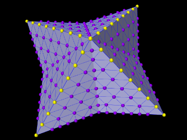
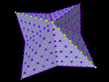
Ellipsoid Joint
An EllipsoidJoint (illustrated below) has been added that has similar functionality to the ellipsoid and scapulothoracic joints found in OpenSim. Details are given in Section 3.4.11 (“Ellipsoid joint”) in the ArtiSynth Modeling Guide.
Joint locking
Individual joint coordinates within any joint derived from the JointBase class can now be locked, such that the coordinate value will remain fixed and the corresponding degree of freedom is removed. Coordinate locking can be controlled using the following methods:
Inertial damping
An inertialDamping property has been added to both the MechModel and RigidBody classes. If not explicitly set in a
rigid body, its value is inherited from the containing MechModel. If non-zero, inertial damping applies a spatial damping
force ![]() to a rigid body that is equal to
to a rigid body that is equal to
| (1) |
where ![]() is the inertialDamping,
is the inertialDamping, ![]() is the body’s
is the body’s ![]() spatial inertia matrix, and
spatial inertia matrix, and ![]() is the body’s spatial
velocity. This offers two advantages over translational/rotational damping:
is the body’s spatial
velocity. This offers two advantages over translational/rotational damping:
-
1.
It is independent of the location of the body’s coordinate frame with respect to its center of mass;
-
2.
There is no need to adjust two different translational and rotational parameters or to consider their relative sizes, as these considerations are contained within the spatial inertia itself.
Inertial damping can be get/set with the MechModel or RigidBody methods
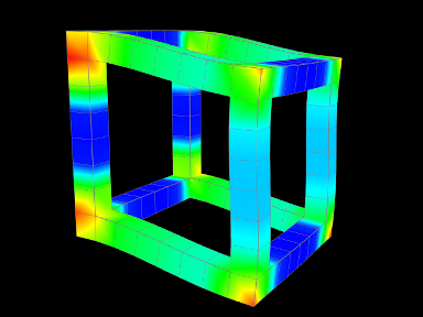
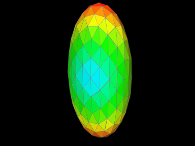
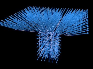
Field and stress/strain visualization
Visualization capabilities for fields
New functionality has been added for visualizing both the scalar and vectors fields that can be defined for FEM models, mesh components, or grids. Full details are given in Section 6.10.8 (“Visualizing fields”) of the ArtiSynth Modeling Guide, and examples are given in Sections 6.10.9 and 6.10.10. Illustrations of some of these visualizations are given below:
|

|
New FEM stress/strain rendering
New types have been added to the FEM surfaceRendering property for controlling stress/strain rendering:
- MaxShearStress
-
renders the maximum shear stress
- MaxShearStrain
-
renders the maximum shear strain
Details are given in Section 6.11 (“Rendering and Visualizations”) of the ArtiSynth Modeling Guide.
New functionality for locating FEM nodes
New functionality has been added to make it easier for users to select node sets within an FEM model. This can be done either in the GUI or in code, and is useful for specifying nodes that need to be attached to other components or otherwise handled specially within the model.
Selecting nodes in the GUI
A node selection tool has been added to the GUI and can be invoked by first selecting a FEM model and then choosing “Select nodes ...” from the context menu. This tool is described in detail in Section 4.7 (“Selecting FEM nodes”) of the User Interface Guide, and includes features for selecting nodes based on
-
•
distance from a mesh
-
•
minimum path between nodes
-
•
nodes covering a surface patch
-
•
nodes lying along an edge, as illustrated below, both with branching (left) and without (right).

|
In addition, the node selection tool allows the selected nodes to be saved to a node file which can then be read by the model’s build code.
Locating nodes in code
New FEM methods have also been added for locating nodes in code, as described in Section 6.4.5 (“Finding which nodes to attach”) in the ArtiSynth Modeling Guide. These include:
Nodes can also be read from a node file that has been saved from the viewer’s node selection tool. Methods for doing this are defined in the NodeNumberReader class and include
as described in Section 6.4.5 (“Selecting nodes in the viewer”).
Enhancements to numeric probes and displays
Smoothing operations
It is now possible to apply smoothing operations to the data in numeric probes. These operations include moving average and Savitzky Golay smoothing. Smoothing can be invoked either from the GUI, as described in the section “Smoothing data” of the User Interface Guide, or in code, using the probe methods
as described in the section “Smoothing probe data” of the Modeling Guide.
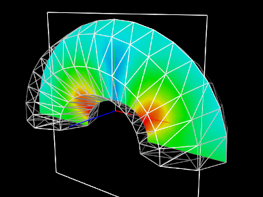
Improved trace control for numeric displays
The legend panel for numeric probe displays has been enhanced with additional controls for adjusting the ordering and visibility of traces:
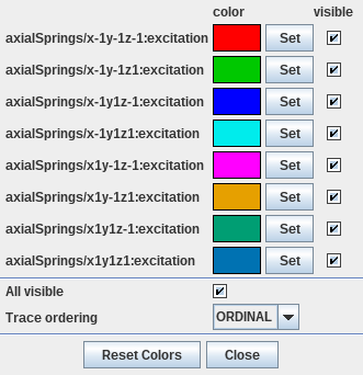
These include an All visible button for making all traces visible/invisible; a Trace ordering operation for ordering the traces according to various criteria; and a Reset Colors operation to reset the colors for any new ordering. Details are given in the section “Legends and visibility control” of the User Interface Guide.
Enhancements to viewer interaction
Improved transformer usability
Enhancements have been made to improve the usability of the viewer transformer tools. These are detailed under various subsections of Section 5.2 (“Transformer Tools”) of the User Interface Guide:
-
•
Flipping axes forward, using the ‘f’ key, to help make them more accessible in the viewer (Section 5.2.4). This is show below: axes are initially obscured (left) and then brought forward after hitting the ‘f’ key (right).

-
•
Increasing transformer size, using the CTRL u or UP_ARROW keys (Section 5.2.5).
-
•
Decreasing transformer size, using the CTRL d or DOWN_ARROW keys (Section 5.2.5).
-
•
When selecting a set of point-like objects that lie within a plane or along a straight line, the transformer axes will be aligned with these features if the alignDraggersToPoints property is set to true using the Settings menu (Section 5.2, top).
In addition, where possible, the system now tries to remember changes to transformer positioning or sizing for particular components.
Constraining mouse motions for view control
A new viewer property, viewControlMask, can be used to restrict mouse-based view control to motions along either the x or y screen directions. See Section 3.9.1 (“Viewer-specific properties”) in the User Interface Guide.
ControlPanel property widgets with multiple hosts
Control panels can now contain property widgets that control the same property across multiple host components. As described in Sections 5.1 (“Control Panels”) of the ArtiSynth Modeling Guide, these can be created with methods of the form
General polygon intersection code
A new class PolygonIntersector has been added for intersecting 2D and 3D planar polygons. It is implemented using GPCJ (General Polygon Clipper for Java).
Aug 14, 2022
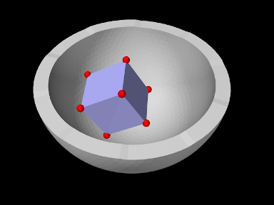
Elastic foundation contact
Elastic foundation contact (EFC) has been formally added to ArtiSynth, and is available via the class LinearElasticContact in the package artisynth.core.materials. It builds on top of ContactForceBehavior, which has been modified slightly and also moved to the materials package.
EFC was originally implemented by Stavness and Sagl, based on a formulation described by Bei and Fregly in “Multibody dynamic simulation of knee contact mechanics”, Medical Engineering and Physics, 2004.
Once created, an EFC can be added to a collision behavior using its setForceBehavior() method. For example:
The YoungsModulus and thickness properties can be bound to a field in case an application requires them to vary over the mesh surface. Mesh field components (see below) have been added to support this.
An illustration of the pressure resulting from EFC between a ball and bowl is shown below:
Full details are given in the section “Elastic foundation contact”, in the (new) “Contact and Collisions” chapter of the Modeling Guide.
New collision chapter in the Modeling Guide
The Modeling Guide has been revised to include a new “Contact and Collision” chapter specifically dedicated to explaining collision handling in greater detail, with additional code examples added to artisynth.demos.tutorial.
Collision rendering property “colorMapCollidable” changed to “renderingCollidable”
The collision rendering property colorMapCollidable, exported by both CollisionManager and CollisionBehavior, has been changed to renderingCollidable, and now controls the collidable for which normals and contact forces are rendered, in addition to the color map. The set/get accessors for colorMapCollidable still exist in deprecated form.
Field components moved to artisynth.core.fields
All application-level field components have been moved to the new package artisynth.core.fields, in order to reduce clutter in other packages. Moved field components and their previous packages are listed below:
| Component | Previous package |
|---|---|
| ScalarGridField | artisynth.core.modelbase |
| VectorGridField | artisynth.core.modelbase |
| ScalarNodalField | artisynth.core.femmodels |
| ScalarElementField | artisynth.core.femmodels |
| ScalarSubElemField | artisynth.core.femmodels |
| ScalarNodalField | artisynth.core.femmodels |
| ScalarElementField | artisynth.core.femmodels |
| ScalarSubElemField | artisynth.core.femmodels |
| VectorNodalField | artisynth.core.femmodels |
| Vector3dNodalField | artisynth.core.femmodels |
| VectorNdNodalField | artisynth.core.femmodels |
| MatrixNdNodalField | artisynth.core.femmodels |
| VectorElementField | artisynth.core.femmodels |
| Vector3dElementField | artisynth.core.femmodels |
| VectorNdElementField | artisynth.core.femmodels |
| MatrixNdElementField | artisynth.core.femmodels |
| VectorSubElemField | artisynth.core.femmodels |
| Vector3dSubElemField | artisynth.core.femmodels |
| VectorNdSubElemField | artisynth.core.femmodels |
| MatrixNdSubElemField | artisynth.core.femmodels |
API change for binding properties to fields
Some component properties, primarily those related to FEM materials, can be bound to a field such that their value varies over the field domain. The API method for binding some property XXX to a field component of type T has been changed from
to
In other words, the second argument useRestPos has been removed. This argument applied only to the grid-based fields ScalarGridField and VectorGridField, and specified whether or not rest positions should be used when determining values for points within an FEM mesh. Instead, this behavior should now be specified by setting the new useFemRestPosition property within ScalarGridField or VectorGridField.
Field components for meshes
Additional field components have been added to the package artisynth.core.fields to describe fields on meshes. At present, the mesh types are restricted to triangular polygonal meshes. The field component include:
- ScalarVertexField
-
Specifies scalar values at the mesh vertices. Values at points not lying on a vertex are determined by first finding the nearest (triangular) face to the point, and then interpolating from the vertex values using the barycentric coordinates of the nearest point.
- VectorVertexField
-
Specifies a vector value at the mesh vertices. Values at points not lying on a vertex are determined by first finding the nearest (triangular) face to the point, and then interpolating from the vertex values using the barycentric coordinates of the nearest point.
- ScalarFaceField
-
Specifies scalar values at the mesh faces. Values at points not lying on a face are determined by finding the nearest (triangular) face to the point, and then using the value for that face. Note that this implies the field will generally be discontinuous.
- VectorFaceField
-
Specifies vector values at the mesh faces. Values at points not lying on a face are determined by finding the nearest (triangular) face to the point, and then using the value for that face. Note that this implies the field will generally be discontinuous.
A primary use of mesh fields is to bind them to property values associated with elastic foundation contact. In particular, the YoungsModulus and thickness properties of LinearElasticContact can be bound to fields.
The vector fields can be defined for any VectorObject. Subclasses for specific vector objects include:
Apr 13, 2022
ArtiSynth 3.7 has been released and is available on the website. This contains all current updates.
Update to the Pardiso solver
The Pardiso solver version has been updated to 2021.1.1, and contains support for solves with multiple right hand sides. This is in preparation for the coming addition of implicit friction integration, which will allow large Coulomb friction forces to be incorporated into FEM models.
Mar 28, 2022
New OpenSim muscle materials
New muscle and ligament materials based on OpenSim have been added to core.materials:
| Material | Description |
|---|---|
| Thelen2003AxialMuscle | rigid-tendon version of the OpenSim Thelen2003Muscle |
| Blankevoort1991Ligament | implements the OpenSim Blankevoort1991Ligament |
| Millard2012AxialMuscle | rigid-tendon version of the OpenSim Millard2012 muscle |
Jan 28, 2022
Improved I/O for FEM models
The ART file format for FEM models has been modified for greater efficiency:
-
•
Rest positions for FemNode3d are no longer written to ART files if they are the same as the current position.
-
•
Nodes for elements and FemMeshComp attachments are now stored and read by node number instead of component path name. The previous format is still valid.
-
•
Meshes in FemMeshComp are now written internally, using the tag ’meshdata’, if they are polygonal, not associated with a file, and do not contain colors, textures, or explicit normals.
Changes to maspack
-
•
Added solvers.MurtyLCPSolver to implement Murty’s method for LCPs and BLCPs, including block pivoting.
-
•
Added matrix.SparseCRSMatrix as a simpler CRS-based sparse matrix replacement for SparseMatrixCRS.
-
•
Added methods to matrix.SparseBlockMatrix: removeRows(), removeCols(), addBlock(bi,bj,Matrix), mul(MatrixNd,MatrixNd), mulLeft(MatrixNd,MatrixNd), and mulTransposeRight(MatrixNd,MatrixNd).
-
•
Added matrix.SparseBlockSignature to represent the structure of sparse block matrices.
Sep 16, 2021
Some follow on updates from the Sep 12 update:
Ability to set the UI look and feel
A property called lookAndFeel has been added to the layout preferences, which allows one to set the UI look and feel, which is based on Java Swing. See the “Layout preferences” section of the User Interface Guide.
More command line option changes
Command line options related to the layout have been modified. The options -noTimeline and timelineRight have been removed, and the following have been added:
| Option | Description |
|---|---|
| -timelineVisible | show the timeline at startup |
| -timelineHidden | hide the timeline at startup |
| -timelineLocation <loc> | set the timeline location relative to the main frame |
| -jythonLocation <loc> | set the Jython console location relative to the main frame |
| -lookAndFeel <laf> | set the UI look and feel |
Viewer property change
The viewer property axisLengthRadiusRatio, used when rendering coordinate axes as solid arrows, has been replaced with axisRadiusRatio, with the value of the latter the inverse of the former.
Sep 12, 2021
A number of updates have been made, mainly with respect to the user interface, allowing model and script menus to be customized, and other settings and configuration information, including startup models, the external classpath, and movie maker settings, to be stored in a user-specific configuration folder. Other changes include a new stop-all button that will halt both simulation and Jython scripts, and new API support for removing model components in code.
New user configuration folder
In order to separate user-specific settings from the ArtiSynth installation, ArtiSynth now creates the configuration folder ArtiSynthConfig in the user’s home folder, and uses this to store various items such as preferences, model and script menus, the startup model, model and script history, and the external classpath.
Revised model menu with editing
The model menu, located under Models in the main menu bar, has been revised to include a number of new entries at the end:
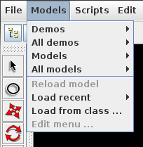
The “Reload model” and “Load from class ...” entries have been relocated from the File menu, “Load recent” has replaced “Recent”, and the entry “Edit menu ...” opens a model menu editor that allows interactive editing of the upper portion of the menu.
For details on menu editing, see “Customizing the Model and Script Menus” in the User Interface Guide.
The XML files describing the model menu have also changed. The XML format has been simplified, and the default menu file has been moved from demoMenu.xml in the ArtiSynth installation folder to settings/modelMenu.xml in the user configuration folder.
Revised script menu with editing
The script menu, located under Scripts in the main menu bar and used to run Jython scripts, has been revised to include new entries and make it feel-compatible with the model menu:
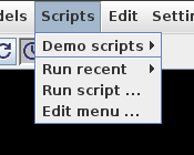
“Run script ...” replaces “Load script” and opens a dialog that allows the user to select a script, while “Run recent” reruns recently run scripts.
The upper part of the script menu can be customized with an arrangement of entries invoking specific scripts. This menu can be customized in the same manner as the model menu by selecting “Edit menu ...” at the bottom. Script menu information is contained in the file settings/scriptMenu.xml in the user configuration folder. The default menu supplies an entry “Demo scripts” that expands to all scripts located in
src/artisynth/demos/scripts
relative to the ArtiSynth installation folder.
Revised settings menu
The Settings menu has been revised to allow additional control over application properties related to the viewer, simulation control and GUI interaction. These are collected into the menu items “Viewers ...”, “Simulation ...”, “Interaction ...”, and “Mouse ...”.
With respect to the previous entries, “Background color” and “Selection color” are now controlled under “Viewers ...”; “Mouse preferences ...” is now “Mouse ...”; and “Enabled articulated transforms”, “Visual display rate”, “Real-time scaling”, and “Init draggers in world coords” are controlled by the properties articulatedTransforms, frameRate, realTimeScaling, and initDraggersInWorld located under “Interaction ...”.
See the “Settings” section in the User Interface Guide.
New preferences settings
Many application properties, including those related to the viewer, simulation control, GUI interaction, window layout, and movie making can now be set permanently via the preferences editor, which can be opened via Settings > Preferences ....
See the “Preferences” section in the User Interface Guide.
New stop-all button
The play controls have been extended to include a new stop-all button:
Located at the right with a square icon, this buttons stops simulation (in the same manner as the pause button), but also aborts any currently running Jython command or script.
New support for deleting components in code
A new static method has been added to ComponentUtils:
where comps is a list of model components. This can be used to “prune” components and their dependencies from existing models, with a behavior that should be identical to selecting the components in the GUI and then choosing Delete from the context menu.
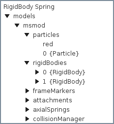
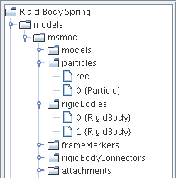
Simplified navigation panel visuals
The navigation panel visuals have been simplified so that composite component entries are now indicated with arrow icons (below, left), instead of folders and lines (below, right):
|
Startup model now settable within ArtiSynth
A startup model can now be set from within ArtiSynth to specify a model (with optional build() method arguments) to be loaded when the application first starts. To do this, select Settings > Startup model .... This capability replaces the need to specify such models using the command line option -model <modelName> (although this command line option is still supported).
See “Setting a startup model” in the User Interface Guide.
External classpath now settable within ArtiSynth
The external classpath, which contains class folders and JAR files for models and packages located outside of artisynth_core, can now be set from within ArtiSynth. To do this, select Settings > External classpath ..., which opens an external classpath editor. This capability replaces the need to edit the EXTCLASSPATH file by hand. The EXTCLASSPATH file has also been moved to the user configuration folder.
See “Setting the external classpath” in the User Interface Guide.
Libraries now updatable within ArtiSynth
It is now possible to update the JAR files and native libraries from within ArtiSynth, instead of calling
bin/updateArtisynthLibs
in the ArtiSynth installation folder. Choose Update libraries from the File menu.
Movie maker updates
-
•
The default folder for movie files is now ArtiSynthConfig/movies under the user’s home folder. This can also be customized via Settings > Preferences > Movies > movie folder.
-
•
A new Messages tab has been added to the movie panel, which displays the progress of move making commands along with any error messages.
-
•
Customized command settings for the encoder options FFMPEG, MENCODER, and AVCONV can now be stored permanently via Settings > Preferences > Movies and selecting Customize Method for the selected method. In addition, there is a new CUSTOM method which can be set to any command-line based movie making command available on the ArtiSynth host computer.
-
•
An explicit stop time can be set indicating when movie recording should stop.
See the updated section “Making Movies” in the User Interface Guide.
Revised command line arguments
The following command line options have been modified or removed:
| Option | Change |
|---|---|
| -largeTimeline | replaced with -timelineWidth <width> and -timelineHeight <height> |
| -timelineZoom <level> | replaced with -timelineRange <time> |
| -historyFile <file> | removed |
| -updateLibs | removed; choose File > Update libraries from the main application menu instead |
| -demosMenu <file> | renamed; use -modelMenu <file> instead |
| -demosFile <file> | renamed; use -demoFile <file> instead |
Enhanced help menu
On systems where Java-browser integration is supported, the Help menu has been expanded to open browser windows to the modeling guide, user interface guide, MATLAB interface manual, and Java API.
Jython documentation moved to the User Interface Guide
Documentation for the Jython interface has been moved from the “Interfacing ArtiSynth to MATLAB and Jython” to the new section “Jython Interaction and Scripting” in the User Interface Guide, and the original manual has been renamed to “Interfacing ArtiSynth to MATLAB”.
Mar 5, 2021
ArtiSynth 3.6 has been released and is available on the website.
Mar 4, 2021
Pardiso updated to MKL 2021
The Pardiso solver has been updated to MKL 2021.1. Users updating from github should also run the command updateArtisynthLibs.
New joint components
A number of new joints have been added to ArtiSynth, including:
-
•
SliderJoint: 1 DOF joint allowing translation along the
 axis.
axis. -
•
CylindricalJoint: 2 DOF joint allowing translation and rotation along the
axis. -
•
SkewedUniversalJoint: 2 DOF roll-pitch joint in which the roll-pitch axes may be at a skewed angle relative to each other.
-
•
PlanarJoint: 3 DOF joint allowing translation and rotation in the
 -
- plane.
 -
•
PlanarTranslationJoint: 2 DOF joint allowing translation in the
- plane.
In addition, the following joints have been added to replace RevoluteJoint, RollPitchJoint and SphericalRpyJoint:
-
•
HingeJoint: Identical to RevoluteJoint, except that its coordinate
 is oriented
counter-clockwise about the axis instead of clockwise.
is oriented
counter-clockwise about the axis instead of clockwise. -
•
UniversalJoint: Identical to RollPitchJoint, except that its roll-pitch coordinates
 are computed with
respect to the rotation
are computed with
respect to the rotation  from frame C to D, instead of the
rotation
from frame C to D, instead of the
rotation  from frame D to C.
 -
•
SkewedUniversalJoint: Identical to SphericalRpyJoint, except that its roll-pitch-yaw coordinates
 are computed with respect to the
rotation from frame C to D, instead of the rotation
from frame D to C.
are computed with respect to the
rotation from frame C to D, instead of the rotation
from frame D to C.
Rendering of the new joints is also controlled differently, with the properties shaftLength, shaftRadius, and jointRadius used to control the size of the shaft and ball structures that are drawn for visualization.
The old joints RevoluteJoint, RollPitchJoint and SphericalRpyJoint are still supported for legacy purposes.
Full details on the new joints, along with examples, are given in the “Joint components” section of the Modeling Guide.
Expanded joint documentation and custom joints
The documentation in the Modeling Guide describing how joints and connectors are created, used and implemented has been enhanced, with new sections describing constraints, coordinates, constraint forces, and rendering. In addition, the joint implementation has been refactored to make it easier to create custom joints, with full details given in the section “Custom Joints” in the chapter “Mechanical Models II”.
API changes for joints and connectors
Some small changes have been made to the methods for joints and connectors:
-
•
In joints and connectors which are subclasses of BodyConnector, numUnilateralConstraints(), which returned the number of engaged unilateral constraints, has been renamed to numEnagedUnilateralConstraints(). Similarly, in subclasses of RigidBodyCoupling, numUnilaterals() has been renamed to numEnagagedUnilaterals().
-
•
In joints and connectors which are subclasses of BodyConnector, numUnilateralConstraints() now returns the total number of unilateral constraints, engaged or otherwise. Similarly, in subclasses of RigidBodyCoupling, maxUnilaterals() has been renamed to numUnilaterals().
-
•
In subclasses of BodyConnector, the spatial forces returned by the methods getBilateralForceInA() are now given in world coordinates. This was done to be consistent with Frame and RigidBody, whose forces (returned by getForce()) are also given in world coordinates.
-
•
In SphericalJoint, rendering of the joint as a ball is now controlled by setting its jointRadius property, together with the faceColor rendering property, instead of the previous method of using point rendering properties.
In addition to these changes, the penetration tolerance for unilateral constraints which are rotary in nature is now controlled by the rotaryLimitTol property, exported by both MechModel and the joint classes.
New methods are also provided for determining the constraint forces acting on a joint in different coordinate frames:
Reimplementation of skinning
The class SkinMeshBody, which implements skinning, has been rewritten to allow skinned meshes which are connected to FEM models to behave properly under FEM rotation.
The SkinMeshBody API has also been refactored to allow greater flexibility in determining the connection weights between the mesh vertices and the underlying rigid bodies and FEM models. Markers and points can now be attached to a SkinMeshBody, even in the absence of a mesh, and this can be used as an simpler, more approximate way to implement muscle wrapping behavior.
Full details on the updated skinning mechanism and how to use it are given in the new chapter “Skinning” in the Modeling Guide.
Improvements to large probe displays
Large probe displays have been rewritten to provide higher quality plotting, better interactive control, and the ability to export plots to svg, postscript, and image files.
Full details on these changes are given in the “Large displays” section of the User Interface Guide. To give a sense of the difference, the old display looked like this,
while the new display looks like this:
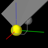
Solid arrow rendering of coordinate frames
Frames and rigid bodies now have a new property called axisDrawStyle, that specifies how coordinate axes should be drawn. Its type is the enumerated type Frame.AxisDrawStyle, with the possible values OFF, LINE, and ARROW. Setting it to ARROW will cause coordinate axes to be rendered as solid arrow, as in this example:
MAPStress and MAPStrain added to FEM surface rendering
The enumerated type FemModel.SurfaceRender, which controls the rendering of FEM surface meshes through an FEM model’s surfaceRendering property, has been extended to include MAPStress and MAPStrain, which render the surface as a color map using the maximum absolute values of the principal stress and strain components, respectively.
Apr 16, 2020
Refactoring of the TrackingController
The TrackingController, which provides ArtiSynth’s inverse modeling capabilities, has been refactored. This includes both internal code reorganization and harmonization of the API.
Organization of cost and constraint terms
The basic usage model for the tracking controller remains the same: an application creates an instance of TrackingController, adds it to the root model’s controllers using addController(), and then populates it with various cost and constraint terms for the quadratic program that is used to solve for excitations. However, the class organization for these terms has been redesigned.
All terms now implement the interface QPTerm, with a base implementation provided by QPTermBase. A QPTerm also uses getType() to specify its type, which is defined by the enumerated type QPTerm.Type and is either COST (cost term), INEQUALITY (inequality constraint), or EQUALITY (equality constraint). These are implemented by subinterfaces of QPTerm: cost terms by QPCostTerm (with base implementation QPCostTermBase) and constraint terms by QPConstraintTerm (with base implementation QPConstraintTermBase). The interface LeastSquaresTerm (with base implementation LeastSquaresTermBase) implements both cost and constraint terms.
All cost and constraint terms are added to the controller as subcomponents. Before performing each inverse computation, the controller checks its subcomponents to find which terms to use.
Internal vs. external terms
Cost and constraint terms are now either internal or external to the controller. Internal terms include:
The MotionTargetTerm and BoundsTerm are always present in the controller and can be accessed using getMotionTargetTerm() and getBoundsTerm(). Other internal terms can be added, removed or queried using add, get and remove methods. For example, for the ForceTargetTerm, these methods are addForceTargetTerm(), getForceTargetTerm(), and removeForceTargetTerm().
External terms include
as well as any custom terms implemented by an application. External terms can be added added, removed and queried using
The previous methods addInequalityTerm and addEqualityTerm have been replaced by addConstraintTerm.
The add and remove methods for external terms should not be used for the internal terms. While it is possible to create an instance of an internal term, such as MotionTargetTerm, and add it to the controller using addCostTerm(term), this will simply add an additional motion term to the controller that is separate from the internal one.
Excitation components now stored using ExciterComp
The excitation components used by the controller were previously stored in a subcomponent list called "exciters". This was actually incorrect since ArtiSynth components can not belong to more than one list at a time. In the revised implementation, "exciters" is now a list of ExcitationComp objects, each of which contains a reference to an excitation component along with an associated weight. This means that excitation weights can now be set interactively by changing the weight property in each ExcitationComp.
Some term properties moved to the controller
The following properties, which were previously present in some individual cost and constraint terms, have now been moved to the controller itself and should be set and queried there:
  useTimestepScaling
  useTrapezoidalSolver
  normalizeH
  useKKTFactorAndSolve
Target and source components now stored within their cost terms
The previous version of the tracking controller contained the following subcomponents, listing various target and source components for the MotionTargetTerm and ForceTargetTerm:
In the refactored controller, the force and motion target terms have been reimplemented as composite components, each maintaining lists of their target and source components. Since (as indicated above) all cost and constraint terms are now stored as controller subcomponents, the resulting component hierarchy now looks like this:
ForceMinimizationTerm renamed to ForceEffectorTerm
The ForceMinimizationTerm class has been renamed to ForceEffectorTerm, since it now permits the forces produced by certain force effectors (those which implement ForceTargetComponent) to be set to a particular target force. Setting that target force to zero (which is the default value) will minimize the force. Likewise, the ForceMinimizationTarget class, which was used to describe each force effector controlled by the ForceEffectorTerm, has been renamed to ForceEffectorTarget.
“Enabled” property replaced with “active”
The property enabled, which was used to enable or disable the controller, and was controlled using setEnabled(enable) and getEnabled(), has been replaced by the property active, which is controlled using setActive(enable) and getActive() (and already existed in the controller’s base class).
Different names for probes created by InverseManager
The names and file names of the probes created by the InverseManager have been changed to be more consistent. This affects any of the probes created by the following methods:
Probes created by the InverseManager are now identified by an enumerated type, InverseManager.ProbeID, as described in the next section. The old and new names associated with these probes are:
| Probe | old name | new name |
|---|---|---|
| TARGET_POSITIONS | "target positions" | unchanged |
| TARGET_FORCES | "target forces" | unchanged |
| INPUT_EXCITATIONS | "input excitations" | unchanged |
| TRACKED_POSITIONS | "target positions" | "tracked positions" |
| SOURCE_POSITIONS | "model positions" | "source positions" |
| COMPUTED_EXCITATIONS | "input excitations" | unchanged |
while the old and new file names are:
| Probe | old name | new name |
|---|---|---|
| TARGET_POSITIONS | "ref_targetPos_input.txt" | "target_positions.txt |
| TARGET_FORCES | "ref_targetForce_input.txt" | "target_forces.txt" |
| INPUT_EXCITATIONS | "excitations_input.txt" | "input_excitations.txt" |
| TRACKED_POSITIONS | "ref_target_positions.txt" | "tracked_positions.txt" |
| SOURCE_POSITIONS | "model_target_positions.txt" | "source_positions.txt" |
| COMPUTED_EXCITATIONS | "excitations.txt" | "computed_excitations.txt" |
To revert to the previous naming conventions, applications can set the static attribute InverseManager.useLegacyNames to true.
Different default probe update interval
The TrackingController property probeInterval, which controls the update interval for the output probes created by
now has a default value of -1, which causes the output probes to be updated at the current simulation rate. The previous default value was 0.01. To revert to this value, one can set the static attribute TrackingController.DEFAULT_PROBE_INTERVAL to 0.01.
Refactoring of the InverseManager
The InverseManager, which is a utility class for creating probes and a control panel for use with the tracking controller, has been refactored so that all its methods are now static and take a root model as one of their arguments. The primary methods are:
As before, the addProbes() method creates three input probes and three output probes. Each probes starts at time 0 and has a stop time indicated by duration, while the output probes have an update interval given by interval. The probes themselves are now identified by the enumerated type InverseManager.ProbeID. The input probes are:
Once created, these can be located and managed within the root model using the InverseManager methods
The output probes are:
and can be located within the root model using the method
Also as before, the createPanel() method creates a control panel for viewing and adjusting controller properties, and adds it to the root model. After, the panel can be located within the root model using the method findInversePanel(root).
Similar to before, the TrackingController supplies the convenience methods
which create probes and panels, with createProbes(rootModel) and createProbesAndPanel(rootModel) using the controller’s probeDuration and probeInterval properties to supply the duration and interval information.
More details on the InverseManager can be found in its API documentation.
Jan 22, 2020
Export for numeric probes
It is now possible to export numeric probe data as either a .csv or .txt files. To do this, select the probe (in either the navigation panel or the timeline), and choose Export or Export as ... from the context menu.
Resetting the initial state
The RootModel now contains the method resetInitialState(), which causes the initial state (i.e., the state at time 0) to be reset to the current state.
This can also be called interactively using the new reset state
button
![]() located at the top left.
located at the top left.
Disabling realtime simulation
By default, when running with graphics enabled, the simulation tries to run in real time, with the simulation slowed down (if necessary) so it does not proceed faster then real time. This can now be disabled, using the Main method setRealTimeAdvancement(enable), so that the simulation runs as fast as possible. Note that real-time advancement is disabled by default when running in batch mode, which is why batch simulations sometimes run faster.
Real-time advancement can also be controlled with the new real-time enable button
![]() located at the top left.
located at the top left.
Full play controls added to the main viewer
The play controls in the main viewer have been extended to include the skip-back and skip-forward buttons that advance the model across waypoints.
Embedded FEM support
A new set of utility methods has been added for creating embedded FEM models, and in particular voxelized embedding FEMs. The utilities were originally created by Antonio Sánchez and have now been added to the package core.femmodels, with the main class being EmbeddedFem. Two of its principal methods are:
Sep 19, 2019
Enhancements to saving models
When saving a model to a file using the Save model as ... menu item, users can now choose the following options:
- Save waypoint data:
-
Causes the state data for any valid waypoints to be saved in addition to the waypoint locations. This is optional because a large number of waypoints may significantly increase the file size for models with large state sizes.
- Core components only:
-
Save only those components which are present in the main artisynth_core package. Any non-core components, and any other components which have a hard dependency on them, will not be written, and the user will be advised of this via a message dialog. The root model is saved as a pure instance of RootModel, instead of the application-specific class that was used to build it. This means that any properties or class overrides specific to the application root model class will not be present in the saved model. The advantage to storing a model using only core components is that it can be loaded by any other user running that same ArtiSynth version, without needing access to any application-specific classes.
Enhancements to waypoint data
Waypoint data files (such as those written using the menu items Save waypoints as ... and Save waypoints) now contain annotations so that when they are later loaded into a model, checks are performed to help ensure that the state is consistent with that model.
Easier reading and writing of meshes
It is now possible to construct, read, or write any of the mesh components (PolygonalMesh, PolylineMesh, PointMesh) by simply specifying a file and then have the file format inferred directly from the file suffix. The currently supported file formats, and their applicability to the different mesh types, are given in the table below:
| Suffix | Format | PolygonalMesh | PolylineMesh | PointMesh |
|---|---|---|---|---|
| .obj | Alias Wavefront | X | X | X |
| .ply | Polygon file format | X | X | |
| .stl | STereoLithography | X | ||
| .gts | GNU triangulated surface | X | ||
| .off | Object file format | X | ||
| .vtk | VTK ascii format | X | ||
| .vtp | VTK XML format | X | X |
The new constructors are
and the new read/write methods are:
For the latter methods, the argument zeroIndexed specifies zero-based vertex indexing (in the case of Alias Wavefront .obj files), while fmtStr is a C-style format string specifying the precision and style with which the vertex coordinates should be written. (In the former methods, zero-based indexing is false and vertices are written using full precision.)
Note: the method
read (File file, String fmtStr)which was specific to PolygonalMesh, has been removed. In its place, one can use
read (File file, String fmtStr, boolean zeroIndexed)with zeroIndexed set to false.
New scripting commands
New commands have been added to the Matlab and Jython scripting interfaces for saving and loading models and waypoints,
where saveWayPoints specifies whether to save waypoint data and coreCompsOnly specifies whether to save only core components, as described above.
ClassAliases moved to maspack.util
The ClassAliases package, which maps class names onto (shorter) aliases, and now also provides support for checking to see if a class is contained in artisynth_core, has been moved to maspack.util.
Jul 21, 2019
Field components added
Field components have been added to allow the interpolation of both scalar and vector quantities over regular and FEM-based grids. Once created, a field can be “bound” to properties of various FEM materials, allowing the values of these properties to vary over the FEM domain. For example, the stiffness parameters of an FEM material may vary at different points within the volumetric mesh.
Full documentation on creating fields and binding them to materials is given in the new section “Fields”, in the “Finite Element Models” chapter of the the Modeling Guide.
MaterialBundles added to FemModel3d
FemModel3d now supports the ability to add “material bundles”, which allow supplemental materials to be added to the elements of an FEM model. A material bundle can be specified for either all elements or selected elements within the model.
Material bundles are implemented using the class MaterialBundle, and are analogous to MuscleBundle, except that they can be used for any type of FEM material and don’t specify excitation or excitation directions. It is possible to use a MaterialBundle to implement a muscle behavior, by specifying a MuscleMaterial whose excitation and restDir properties are set directly by the application (with the latter possibly attached to a Vector3d field).
Full documentation is given in the new section “Varying and augmenting materials”, in the “Finite Element Models” chapter of the the Modeling Guide.
Refactoring of FEM materials
FEM materials have been refactored in several ways:
-
•
The computeStress() and computeTangent() methods are now consolidated into a single method
computeStressAndTangent() (in which the argument to return the tangent matrix is optional). The main reason for this is efficiency: tangent calculations often require some of the same calculations required for stress, and so computing these quantities in the same method avoids repeated computation. -
•
The property viscoBehavior has been removed from FemMaterial. Instead, viscoelasticity is now effected by creating an instance of ViscoelasticMaterial, which takes both a base material and a viscoelastic behavior.
-
•
FEM materials can now maintain their own custom state. This is done via the interface HasMaterialState, which supplies the methods
// material currently has stateboolean hasState();// creates an object for storing the stateMaterialStateObject createStateObject();// advances the state from time t0 to t1advanceState (MaterialStateObject state, double t0, double t1);For materials which have state, the system creates state instances which are stored at each element integration point and supplied as an additional argument to the computeStressAndTangent() method.
-
•
A new FEM material, ScaledFemMaterial, has been added which takes a base material and a scaling factor. The latter can then be attached to a scalar field to “scale” the effect of the material over an entire FEM. The old way of doing this, which involved a scaling factor in the integration data (class IntegrationData3d), has been removed.
MuscleBundle can now accept shell elements
MuscleBundle and MuscleElementDesc have been extended to allow shell as well as volumetric elements. This means that elements for these objects are now referenced by FemElement3dBase instead of FemElement3d.
AuxiliaryMaterials now deprecated
With the addition of MaterialBundles, the existing means for
added “extra” materials to an FEM, using
AuxiliaryMaterial, is
now deprecated. AuxiliaryMaterials are still used “under the
hood” to implement MuscleBundles, but it is expected that they
will eventually be removed.
An undocumented feature known as AuxMaterialBundle currently
exists within ArtiSynth, which allows
AuxiliaryMaterials to be
added to an FEM model in a manner analogous to MaterialBundle.
To accommodate MaterialBundle, the methods for adding, removing
and accessing AuxMaterialBundles have been renamed as follows:
| Old method | New method |
|---|---|
| getMaterialBundles() | getAuxMaterialBundles() |
| addMaterialBundle(bundle) | addAuxMaterialBundle(bundle) |
| removeMaterialBundle(bundle) | removeAuxMaterialBundle(bundle) |
| clearMaterialBundles() | clearAuxMaterialBundles() |
MuscleElementDesc not longer extends ExcitationComponent
To quickly review: A MuscleBundle is the basic grouping of elements within an FemMuscleModel that share a single excitation value. Each element within a MuscleBundle is described by a single MuscleElementDesc. Removing the ExcitationComponent interface from MuscleElementDesc means that it is no longer be possible to control the excitation for one or more MuscleElementDescs separately from the excitation of the MuscleBundle. In other words, a MuscleBundle now represents the smallest possible grouping of FEM elements for which you can provide a single excitation.
Note that as before, one is still able to combine the excitations of several MuscleBundles using MuscleExciter components.
Other changes
-
•
Excitation component has been simplified by removing the methods
-
•
In the maspack.properties package, added setAllowedTypes() to PropertyDesc, to specify which subclasses of getValueClass() may be used for creating instances of a property within a CompositePropertyPanel.
-
•
In maspack.widgets, modified CompositePropertyPanel to use reflection to look for the method
initializePropertyValues() in the declaration of a CompositeProperty, and use this to help initialize the subproperties of a CompositeProperty based on the value of a previous object with the same base class. -
•
Added the methods getMaxAbsPrincipalStress() and getMaxAbsPrincipalStrain() to FemNode3d.
May 6, 2019
Enhanced rigid body inertia computation
The method by which inertia is automatically computed for a rigid body based on the geometry of its mesh components (when its inertiaMethod is MASS or DENSITY) has been improved. Mesh components now have a property massDistribution which determines how the mesh’s inertia contribution is determined for a given mass. VOLUME, AREA, LENGTH, and POINT indicate, respectively, that the mass is distributed evenly over the mesh’s volume, area (faces), length (edges), or points. The default value is determined by the mesh type: VOLUME for a closed PolygonalMesh, AREA for an open PolygonalMesh, LENGTH for a PolylineMesh, and POINT for a PointMesh. Applications can specify an alternate value providing the mesh has the features to support it. Specifying DEFAULT will restore the default value.should be determined.
Full details are given in the section “Multiple meshes”, located under “Rigid bodies”, in the Modeling Guide.
Saving models in mid-simulation
It is now possible to save a model to a file in mid-simulation.
Previously, it was assumed that the simulation “time” was 0. Now,
however, you can simulate to some time ![]() , and then save the model
(using File > Save model as ...). Loading the resulting file
(using File > Load model ...) will restore the model to the
simulation time
, and then save the model
(using File > Save model as ...). Loading the resulting file
(using File > Load model ...) will restore the model to the
simulation time ![]() .
.
If the model contains valid waypoints, the state of these waypoints is now also saved and restored. One caution is that if there are many waypoints and the model state is large, the resulting save file may also be quite large.
Forces and nodal stress/strains now saved as state
Forces and nodal stress/strain values are now saved as state within
waypoints. This ensures that when a model is reset to a given
waypoint at time ![]() , forces and stress/strains will be reset to the
same values they had when the simulation originally reached
, forces and stress/strains will be reset to the
same values they had when the simulation originally reached ![]() .
.
Improvement and simplification of the state mechanism
The interface HasAuxState, used to indicate components which store state, has been renamed to HasNumericState and moved to artisynth.core.modelbase. It has also been simplified, with the methods skipAuxState() and getInitialState() removed and getAuxState(), setAuxState(), and advanceAuxState() renamed to getState(), setState() and advanceState().
Numerous internal changes have been made to the mechanism by which model state is saved and restored, both from waypoints and from model files, largely with the goal of ensuring exact repeatability of results when simulation resumes from a previously stored state.
Menu command for saving and loading waypoints
A new set of menu commands have been added for saving and loading waypoints. These are accessed from the File menu and include:
- Load wayPoints ...
-
Loads a set of waypoints from a specified file. As before, loading waypoints are superimposed on top of any existing waypoints.
- Save wayPoints as ...
-
Saves the current set of waypoints to a specified file.
- Save wayPoints
-
Saves the current set of waypoints to a previously specified file.
Previously, saving and loading waypoints had to be performed from the timeline. The save file now also includes information for all waypoints, with or without state, along with information identifying breakpoints.
As before, the waypoint data file is binary, since this typically requires half the file size and improves file I/O times by as much as tenfold.
Changes to nodal stress/strain computation and contact rendering
Stress or strain computation can now be explicitly enabled for individual FEM nodes via the computeStress and computeStrain properties of FemNode3d. Otherwise, when needed for Stress or Strain rendering of an FEM mesh, nodal computation of stress/strain is now optimized to require computation of stress/strain values only for those nodes associated with the mesh.
A new property colorMapInterpolation has been added to CollisionManager and CollisionBehavior to control color interpolation when a penetration depth or contact pressure map is requested via the drawColorMap property. The default interpolation is HSV.
Constraint impulses now stored as forces
Bilateral and unilateral constraint impulses are now converted to forces when they are stored in the model. This means that it is no longer necessary to convert impulses to forces by dividing by the simulation time step. In particular:
-
•
The methods setBilateralImpulses(lam,h,idx) and setUnilateralImpulses(the,h,idx) (in MechSystem and Constrainer) have been changed to setBilateralForces(lam,s,idx) and setUnilateralForces(the,s,idx). Within each of these, the forces should be computed from s*lam and s*the.
-
•
The methods getBilateralImpulses(lam,idx) and getUnilateralImpulses(the,idx) have been changed to getBilateralForces(lam,idx) and getUnilateralForces(the,idx).
-
•
Related ’Impulse’ methods have been renamed to ’Force’.
-
•
CollisionResponse.getContactImpulses() has been changed to getContactForces().
-
•
The last argument for ContactForceBehavior.computeResponse() has been changed from region (giving the contact’s penetration region) to contactArea (which gives the estimated average area associated with the contact).
Feb 11, 2019
Muscle wrapping added
Muscle wrapping has now been officially added to ArtiSynth, with documentation supplied by a new chapter called “Muscle Wrapping” in the Modeling Guide. This documentation refers to a number of examples that have been added to artisynth.demos.tutorials.
RigidBody and RigidCompositeBody Merged
It is now possible to add multiple meshes to a RigidBody, subsuming the functionality previously offered by RigidCompositeBody, which is now deprecated.
Each rigid body mesh is stored in a mesh component, RigidMeshComp, which is in turn contained in a subcomponent list named meshes. Meshes can be of any type, including PolygonalMesh, PolylineMesh and PointMesh. The method getSurfaceMesh() returns the first PolygonalMesh in the list, and getSurfaceMeshComp() returns its associated RigidMeshComp.
Meshes can be added to a RigidBody by creating a RigidMeshComp for them and then using methods such as
They can also be added directly, using the methods
which allocate and return a RigidMeshComp. The latter method also specifies hasMass, which indicates if the mesh should contribute to the body’s inertia, and isCollidable, which indicates if it should contribute to the body’s collision mesh.
RigidMeshComp also contains new properties, mass and density, that can directly control how the mesh contributes to the rigid body’s inertia when its inertiaMethod is MASS or DENSITY.
Full details are given in the new section “Multiple meshes”, located under “Rigid bodies”, in the Modeling Guide.
Distance grids stored in DistanceGridComp
A new component, DistanceGridComp, has been added for containing, controlling, and visualizing the distances grids represented by DistanceGrid. Full documentation is given in the new section “Distance Grids and Components” in the Modeling Guide.
In particular, the distance grid for a rigid body has been moved into its own DistanceGridComp, which is a subcomponent of the body named "distanceGrid". One can obtain a reference to the grid component via the method
API changes involving RigidBody
The wrapping code and the removal of RigidCompositeBody have engendered some API changes involving RigidBody.
1) The following methods concerning surface meshes have been renamed. The old methods have been retained but deprecated:
| Old method | New method |
|---|---|
| getMesh() | getSurfaceMesh() |
| setMesh(mesh) | setSurfaceMesh(mesh) |
| setMesh(mesh,fileName) | setSurfaceMesh(mesh,fileName) |
| setMesh(mesh,fileName,X) | setSurfaceMesh(mesh,fileName,X) |
2) The field names for the enumerated type RigidBody.InertiaMethod have been capitalized, so that Density, Mass, and Explicit are now DENSITY, MASS, and EXPLICIT.
3) The rigid body’s distance grid has been moved into its own component, which is a DistanceGridComp that can be obtained via getDistanceGridComp(). The old RigidBody properties for controlling the distance grid have therefore been replaced by their equivalent properties in the grid component:
| Old RigidBody property | New DistanceGridComp property |
|---|---|
| distanceGridRes | resolution |
| distanceGridMaxRes | maxResolution |
| distanceGridOBB | fitWithOBB |
| distanceSurfaceIso | surfaceDistance |
| renderDistanceGrid | renderGrid |
| distanceGridRenderRanges | renderRanges |
In addition, the old RigidBody property renderDistanceSurface has been replaced by the combination of the DistanceGridComp properties renderSurface and surfaceType, along with the new RigidBody property gridSurfaceRendering. The latter, if set true, will cause the grid’s isosurface to be rendered instead of the rigid body mesh components.
4) The component RigidMesh, which allowed wrapping around a rigid body with a general polygonal mesh, has been removed. Instead, wrapping is now supported for all rigid bodies. Wrapping is still computed using analytic methods for the special RigidBody subclasses RigidCylinder, RigidSphere, RigidEllipsoid, and RigidTorus.
5) In the class RigidMeshComp, the property physical has been renamed hasMass. The class no longer contains a distance grid, and so methods and properties relating to this have been removed. Also, the RigidBody method
takes the additional argument isCollidable indicating if the mesh should be treated as collidable.
addFrameMarkerWorld() added to MechModel
A new method, addFrameMarkerWorld(frame,pos), has been added to MechModel. This creates a FrameMarker, attaches it to frame at the position pos in world coordinates, adds it to the MechModel, and returns it. It differs from the existing method addFrameMarker(frame,loc) in that the latter places the marker at the location loc in frame coordinates.
Shell elements added to FemModel
Shell elements have been added to FEM models. Full documentation on this will be provided soon; in the meantime, please note the following:
Shell elements are described by instances of ShellElement3d, and currently include ShellTriElement and ShellQuadElement. They may be added and removed from a FemModel3d using the following methods:
Both shell elements and the usual volumetric elements use the same nodes (FemNode3d), and can share nodes between elements.
Regular volumetric elements are still identified simply as “elements”, and are added and removed using the original methods addElement(e), removeElement(e), etc. In particular, numElements() still returns the number of volumetric elements. In order to query the total number of volumetric and shell elements, one should use the method
When used in connection with a shell element, an FEM node must supply an extra three degrees of freedom which specify a direction vector (known as a director) that is used for the shell computations. By default, this director vector is allocated and initialized automatically. It may be queried using the methods:
API changes related to shell elements
FemElement3d replaced by FemElement3dBase in some cases
Both shell and volumetric elements now subclass from FemElement3dBase. Consequently, some methods which are general to all elements now use FemElement3dBase instead of FemElement3d. This includes the following query methods in FemModel3d:
New and reimplemented element and node queries
The following element and nodal query methods have also been added to FemModel3d:
FemElement3d.hasFace() replaced by containsFace()
FemElement.computeRestVolumes() returns minimum Jacobian determinant
The method FemElement.computeRestVolumes() no longer returns the computed rest volume. Instead, it stores the rest volume in the element and returns the minimum Jacobian determinant that was used in the volume computation. This makes computeRestVolumes() behave the same as computeVolumes(). To obtain the rest volume, one should use getRestVolume():
FemNode3d.getElementDependenices() is deprecated
The method FemNode3d.getElementDependencies() is now deprecated. Instead, one should use the following:
FemModel3d.getElementNeighbors() is deprecated
The method FemModel3d.getElementNeighbors(node) is now deprecated. Instead, one should use one of the FemNode3d methods:
FemModel.ElementFilter is now an interface
The class FemModel.ElementFilter has been changed to an interface.
FemElement3dBase.computePosition() renamed to computeLocalPosition()
The method FemElement3dBase.computePosition(pos,ncoords), which computes a point position within an element based on natural coordinate values, has been renamed to computeLocalPosition(pos,ncoords).
Mar 14, 2018
ArtiSynth has moved to Github
Both the artisynth_core and artisynth_models repositories have been moved to Github, where they can be accessed via the URLs
Users who were working from Subversion checkouts of these projects should replace them with fresh checkouts (’clones’) from Github. Eclipse users should remove their existing artisynth_core and artisynth_models projects from Eclipse, and all users should archive the existing project directories.
The new versions can then be cloned from Github, and libraries should be downloaded for artisynth_core. Eclipse users will also need to unpack the Eclipse project files from eclipseSettings.zip. A Unix-like command line sequence to perform these operations is as follows:
Eclipse users will also need to reimport these new projects into Eclispe. Full details on installing projects from Github are given in the updated installation guides: www.artisynth.org/doc/info/installation.
Note that users with Github accounts and SSH keys may wish to use the SSH URLs instead:
  git@github.com:artisynth/artisynth_core.git
  git@github.com:artisynth/artisynth_models.git
Write access to the old svn repositories for artisynth_core and artisynth_models has been frozen. Users posting changes should first clone the new Github repositories, and then push these changes to Github.
ArtiSynth updated to Java 8
ArtiSynth has been updated to Java 8, and the compilation settings for both Makefiles and Eclipse projects (the latter contained in each project’s eclipseSettings.zip file) have been changed to request Java 8 compatibility.
This should mean that one should also be able to run and compile under Java 9, although we have noted some problems related to Java OpenGL (JOGL) when compiling on Java 9 and then running on Java 8. We therefore recommend that users stay with a Java 8 JDK for the moment. Java 8 is also compatible with current versions of MATLAB.
isActive() method added to monitors and controllers
An isActive() method has been added to the Monitor and Controller interfaces, with a default implementation provided by ModelAgentBase (which also implements a setActive() method and exports active as a property).
This provides the ability to turn monitors and controllers off at run time: those for which isActive() returns false will not be called.
Existing implementations of Monitor or Controller which do not subclass MonitorBase or ControllerBase will need to be augmented to provide an isActive() method.
Jan 15, 2018
Change in ArtiSynth web server
The URL for distributing ArtiSynth libraries and files has changed from artisynth.magic.ubc.ca/artisynth/files to www.artisynth.org/files. This should affect only applications making use of this URL.
However, it does require updating artisynth_core in order to be able to use the bin/updateArtisynthLibs command.
Nov 26, 2017
Elliptic selection
A new elliptic selection method has been introduced, thanks to work by Doga Tekin at ETH. To activate it, select the ellipse icon (second from the top of the selection toolbar). The viewer cursor will then change to include a surrounding ellipse (which defaults to a circle). Dragging while in elliptic selection mode will cause the cumulative selection of all objects visible within the ellipse, in a manner very much like a “paint” selection. If the SHIFT modifier key is pressed, selection is replaced with deselection. The current selection can also be cleared by hitting the ‘c’ key within the viewer. The dimensions of the selection ellipse can be adjusted by dragging with the CTRL and ALT modifier keys pressed, or hitting the ‘d’ key to cause the ellipse to be reset to its default (circular) dimensions.
Full details are given in the “Viewer Selection” section of the User Interface Guide.
http://www.artisynth.org/doc/html/uiguide/uiguide.html
Updated mouse bindings
The mechanism by which mouse bindings are set has been updated. Choosing Setting > Mouse Preferences ... from the main menu will bring up a dialog which allows you to adjust the mouse bindings and wheel zoom scale, and also displays the buttons and modifier keys required for different actions.
Names of the available bindings include ThreeButton, TwoButton, OneButton, Laptop, and Mac. ThreeButton, Laptop, and Mac correspond to the previous bindings default, laptop and mac. TwoButton, OneButton are identical to ThreeButton, except that the middle mouse button is emulated with the ALT key and (for the latter) the right mouse button is emulated using the META key (which is usually WINDOWS or (on Mac) COMMAND).
By default, ArtiSynth now detects the number of buttons on the mouse and sets the bindings to either ThreeButton, TwoButton or OneButton, as appropriate. It is still possible to override the mouse bindings using the -mousePrefs <bindings> command line argument.
Details are given in the “Alternate Mouse Control Settings” section of the User Interface Guide.
Numeric control probes
A new type of input probe, NumericControlProbe, has been added, that takes numeric data and passes it to an application-supplied function which can apply that data in any desired way. This is similar to using a Controller, except that the driving data can be viewed using the timeline displays or loaded from a file. NumericControlProbes are complimentary to NumericMonitorProbes, which were added last June.
For details, see the "Numeric control probes" section of the Modeling Guide.
ProbeDataFunction
The interface NumericMonitorProbe.DataFunction, which could be used to define the data generating function for NumericMonitorProbe, has been lifted to DataFunction and is also used to define the data application function for NumericControlProbe.
Command line options for the MovieMaker
The following command line options have been added to control the MovieMaker:
  -movieFrameRate <rate> # movie frame rate (Hz)
  -movieMethod <method>  # movie making method
The movie method should be currently be one of internal, mencoder, mencoder_osx, ffmpeg, animated_gif, or avconv.
SignedDistanceGrid replaced by DistanceGrid
The class SignedDistanceGrid has been replaced by DistanceGrid, which can be either signed or unsigned. A number of new features have been added to distance grids, including:
-
•
The ability to explicitly specify the center and orientation of the grid with respect to its local coordinate system;
-
•
Writing and scanning the grid to and from a file;
-
•
Grid interpolation based on either linear or quadratic interpolation;
-
•
The ability to either generate the grid from mesh data, or to specify its values explicitly;
-
•
CSG operations based on signed distance grids;
New centering methods for meshes
It is often useful to align the local coordinate system for a mesh with its center, and sometimes also with its oriented bounding box (OBB).
To this end, we have added a number of methods to MeshBase:
The translate and transform methods reposition the vertex positions so as to achieve the required change in local coordinates. Note that this is independent of the additional mesh-to-world transform, controlled by getMeshToWorld() and setMeshToWorld(), that maps from local to world coordinates.
For PolygonalMesh, the following additional method is available:
July 28, 2017
Update to JOGL 2.3.2
The OpenGL rendering package has been updated to JOGL 2.3.2. Since the GL rendering implementation is hidden from the user, this should not affect application source code unless you are using GL directly for some reason. In that case, you will need to replace
with
However, the underlying JOGL libraries have changed, so after you have updated artisynth_core, you will need to run bin/updateArtisynthLibs (or run artisynth with the -updateLibs option) to obtain the new libraries.
Important: if you compile and/or run ArtiSynth from the command line, you will also need to remove from the folder $ARTISYNTH_HOME/lib any existing .jar files beginning with jogl2* or matlabcontrol*. Otherwise, these may conflict with the new libraries. Eclipse users may also wish to do this to remove clutter.
Eclipse users will need to change the JOGL libraries in their build path. Select the project for artisynth_core, and then under Properties... go to Java Build Path > Libraries, and replace
with
Also, make sure that these libraries are exported. Switch to the Order and Export tab and make sure that the export boxes are checked. The last library is used for implementing the MATLAB interface.
This change should allow ArtiSynth to run on versions of MATLAB from 2016 onward (but will prevent it from running on earlier versions).
June 6, 2017
Viewer grid labeling
The viewer grid now provides numeric axis labels, which can be enabled by hitting the ’l’ key in the viewer. Label properties such as size and color and which axes are labeled can be controlled by right clicking in the viewer and choosing Set viewer grid properties.
More details can be found in the "Axis Labeling" section of the User Interface Guide.
Numeric monitor probes
A new type of output probe, NumericMonitorProbe, has been added, which generates data through an application-supplied function. This is similar to using a Monitor, with the added advantage that the generated numeric data can be viewed using the timeline displays or saved to a file.
For details, see the "Numeric monitor probes" section of the Modeling Guide
Rendering signed distance grid surfaces
ArtiSynth components that support signed distance grids, such as RigidBody, now support the ability to render the zero surface associated with the grid. This can controlled through the property renderDistanceSurface. When enabled, this will cause an approximation of the grid’s zero surface to be displayed instead of primary surface mesh. The purpose of this is to allow one to visualize how coarsely the distance grid approximates the mesh on which it is based.
Apr 10, 2017
Constructive solid geometry added to SurfaceMeshIntersector
The SurfaceMeshIntersector class in maspack.collision has been significantly upgraded for improved robustness and now supports the ability to perform constructive solid geometry (CSG) operations between two triangular meshes. The CSG methods include:
which return the intersection, union, and differences (mesh0-mesh1) and (mesh1-mesh0) with respect to mesh0 and mesh1. If the resulting CSG volume is null, then the returned mesh will be empty and its isEmpty() method will return true.
The CSG capabilities rely partly on the following enhanced version of findContoursAndRegions():
Like findContoursAndRegions (cinfo, mesh0, mesh1), this returns true if mesh0 and mesh1 intersect and places the resulting contact information in cinfo. However, the additional arguments regions0 and regions1, which are instances of SurfaceMeshIntersector.RegionType, can be used to specify how the penetration regions for each mesh should be computed:
| INSIDE | Compute regions on the mesh that are inside the other mesh |
|---|---|
| OUTSIDE | Compute regions on the mesh that are outside the other mesh |
| NONE | Do not compute penetration regions |
Some effort has been put into helping ensure that the CSG methods are robust, work well in the presence of degenerate contacts (e.g., edge-edge, vertex-edge, and vertex-vertex), and return meshes that are both closed and manifold. However, it is important to remember that polygonal CSG operations are inherently ill-conditioned and problematic situations are still possible. For example, degenerate contacts are assumed to be within machine precision - essentially, vertices and edges that are within this tolerance are “snapped together”. However, near-degenerate situations which are just outside machine precision may result in ill-conditioned CSG meshes. Also, it is not always possible to ensure that the meshes are manifold in the case of intersections involving non-closed meshes.
Changes to maspack.collision.ContactInfo
Some changes have been made to the ContactInfo structure which returns contact information. This includes the following method name changes:
| Old method | New method |
|---|---|
| getMesh0() | getMesh(0) |
| getMesh1() | getMesh(1) |
| setRegionTol(tol) | setContactPlaneTol(tol) |
| getRegionTol() | getContactPlaneTol() |
| getPenetrationRegions0() | getRegions(0) |
| getPenetrationRegions1() | getRegions(1) |
| getPenetratingPoints0() | getPenetratingPoints(0) |
| getPenetratingPoints1() | getPenetratingPoints(1) |
In addition, the new method getRegionsType(meshNum) can be used to query the type of regions associated with a particular mesh.
Changes to maspack.collision.PenetrationRegion
Because the penetration regions computed for a mesh may now be either inside or outside the opposite mesh, the following methods in PenetrationRegion have been renamed:
| Old method | New method |
|---|---|
| getInsideVertices() | getVertices() |
| numInsideVertices() | numVertices() |
| isInsideVertex (vtx) | containsVertex (vtx) |
| getInsideFaces() | getFaces() |
| numInsideFaces() | numFaces() |
| isInsideFace (vtx) | containsFace (vtx) |
| getInsideEdges() | getEdges() |
| numInsideEdges() | numEdges() |
| isInsideEdge (vtx) | containsEdge (vtx) |
Collision handling support for signed distance grids
The ArtiSynth collision handling mechanism has now been extended to work using signed distance fields, in situations where at least one of the collidable bodies has a fixed mesh and maintains and exports a signed distance grid (via the CollidableBody methods hasDistanceGrid() and getDistanceGrid()). Although more approximate than the methods based on intersecting triangles and contours, signed distance methods can be significantly faster. Signed distance collisions can be activated by setting the collideType property in either the collision manager or a specific collision behavior to ColliderType.SIGNED_DISTANCE.
Updated information on signed distance collisions and the configuration and rendering of signed distance grids is given in the sections “Collision Implementation and Rendering” and “Configuring and rendering signed distance grids” of the ArtiSynth Modeling Guide.
Improved compatibility between Swing and JOGL
Certain compatibility issues between Java Swing and Java OpenGL (JOGL) have been fixed by switching the default JOGL rendering widget from GLCanvas to GLJPanel. This fixes problems including: jumps and widget blanking when dragging the viewer between screens in a dual-monitor setup, the inability of the viewer to reposition itself correctly in MacOS Sierra, and widget blanking under some system configurations when using tiling widget managers.
GLJPanel works by doing all graphics rendering to an off-screen buffer and then copying the resulting pixels into the Swing widget. This introduces a slight overhead but completely isolates Swing from JOGL. In order to fix a known bug, it was also necessary to create our own implementation of GLJPanel in maspack.render.GL.jogl.
GLJPanel is now the default rendering widget. However, one can explicitly ask for either GLCanvas or GLJPanel by starting ArtiSynth with the -useGLJPanel or -useGLCanvas command line options.
Refactoring of FemFactory
A cleanup has been done in artisynth.core.femmodels.FemFactory. This includes some changes to method signatures:
- createTorus() methods:
-
Have been modified so that the nr argument now gives the number of element layers along the inner thickness, instead of the number of node layers (since the latter definition was incompatible with quadratic elements).
- createTube() methods:
-
Have been modified so that the nl and nr arguments now give, respectively, the number of elements along the length and the number of element layers along the thickness, instead of the number of node and node layers (since the latter definition was incompatible with quadratic elements).
- createExtrusion() methods:
-
Have been modified so that all now take an additional argument zOffset which optionally offsets the first element layer from the surface. createTetExtrusion() and createQuadtetExtrusion() have also been restricted to triangular meshes, since it is not otherwise possible to ensure that the resulting FEM elements are conforming.
Return arguments in basic vector methods
Fabien Péan at ETH has provided a patch in which some of the more commonly used Vector methods now return self-references. This allows chaining of computational statements into more compact forms such as
Oct 18, 2016
New collision manager
The ArtiSynth collision manager, which is used by MechModel to manage collisions between collidable bodies, has been rewritten to provide greater control over collision behavior, collision rendering, and the observation of collision responses.
The principal change is that CollisionBehavior objects now contains all information related to collision control, including not just the friction and whether collisions are enabled, but also the parameters used to fine tune the behavior, compliance (if desired), rendering of quantities such as contact normals and points, etc. Collision behavior objects are now stored as subcomponents of the collision manager as proper ArtiSynth components, allowing users to select them and edit their properties. Most of the properties exported by CollisionBehavior are also exported by the collision manager, from which they are inherited by behaviors which have not set them explicitly. Since behaviors are now proper components, they can also be selected and edited using the GUI navigation panel.
Full details are given in the “Collision Handling” section of the ArtiSynth Modeling Guide and, for the GUI aspects, the ArtiSynth User Interface Guide.
By separating behavior and response from the internal collision
handling, the collision manager no longer needs to maintain ![]() collision handlers for all possible collision possibilities. Instead,
handlers are created on demand when a collision is actually observed,
and the collision manager is also free to employ bounding volume
hierarchies to reduce the number of collision checks (although this
has not yet been implemented).
collision handlers for all possible collision possibilities. Instead,
handlers are created on demand when a collision is actually observed,
and the collision manager is also free to employ bounding volume
hierarchies to reduce the number of collision checks (although this
has not yet been implemented).
Collision behavior components
Previously, to make detailed changes to collision behavior, one needed to either specify global properties in the collision manager, or modify properties of the CollisionHandler object that maintains the collision constraints for a specific pair of collidables.
While global behavior properties can still be set in the collision manager, behavior for specific collidables can now be managed by setting the CollisionBehavior components appropriate for the collidables in question. For example, to request the drawing of intersection contours between collidables col0 and col1, one previously would have used a code fragment like this:
Now, one would instead do something like this:
One can also still use the existing setCollisionBehavior methods, which specify whether a collision is enabled, as well as, optionally, its friction. These methods now create a default collision behavior component internally, and return it, after which it can be used to set other collision properties:
One can also retrieve an existing behavior and set its properties:
Because behaviors are now proper components, it is not permissible to add them to the collision manager twice. Specifically, the following will produce an error:
   CollisionBehavior behav = new CollisionBehavior();
   behav.setDrawIntersectionContours (true);
   mesh.setCollisionBehavior (col0, col1, behav);
   mesh.setCollisionBehavior (col2, col3, behav); // ERROR
However, a new behavior can be created from an existing one:
   CollisionBehavior behav = new CollisionBehavior();
   behav.setDrawIntersectionContours (true);
   mesh.setCollisionBehavior (col0, col1, behav);
   behav = new CollisionBehavior(behav);
   mesh.setCollisionBehavior (col2, col3, behav); // OK
Collision behaviors now contain most of the properties that used to be contained exclusively in the collision manager. Most of these are still retained in the collision manager, from which they will be inherited if not explicitly set in the behavior. A behavior can also set its own render properties, which will then be used instead of the collision manager render properties.
Collision response components
Another change is that information about the results of a collision are now collected by CollisionResponse components, which are created the application as needed and also stored as subcomponents of the collision manager. This removes the need for an application to query internal CollisionHandler objects to determine things like contact impulses, mesh interpenetration regions, etc.
For example, to obtain the current contact impulses between two FEM models, one would previously use the following code fragment (perhaps within a monitor apply() method):
This would now be replaced with an earlier call to set up a collision response, perhaps in a build() method,
followed by the following runtime code:
Note also that when setting up a collision response, the second collidable can be a group specification, allowing the collection of information between a specific collidable and an entire group of collidables. For example,
would create a response component to query collision responses between femA and all rigid bodies.
If desired, applications can also instantiate responses themselves and add them to the collision manager:
However, as with behaviors, the same response cannot be added to an application twice:
Specifying the collider
The type of collider used for collisions can now be specified directly in the collision manager through the colliderType property, whose value has the type CollisionManager.ColliderType. TRI_INTERSECTION is the current default, while AJL_CONTOUR specifies AJL collisions. AJL collisions can still be enabled by default through the -useAjlCollisions command line argument.
Rendering penetration depth
Some new properties have been added to allow the rendering of penetration depth when the collider type is set to AJL_CONTOUR. For details, see the new demo demos.tutorial.PenetrationRender and the associated documentation in the “Example: Rendering penetration depth” section of the ArtiSynth Modeling Guide.
This example makes use of the new INACTIVE setting for the method property in CollisionBehavior, which disables the generation of collision constraints and hence turns off the collision response.
Expanded collision groups
Another change is that the special collidable objects Collidable.Deformable, Collidable.Rigid (formerly Collidable.RigidBodies), and Collidable.Self, used to denote all deformable bodies, all rigid bodies, and self collision, respectively, have been made instances of a special subclass Collidable.Group and extended to include Collidable.AllBodies (all rigid and deformable bodies) and Collidable.All (all bodies plus self-collision).
When calling one of the setCollisionBehavior or setCollisionResponse methods, the second argument can be an instance of Collidable.Group, allowing behaviors (or responses) to be established between a specific collidable and all members of a group. So for example,
would set the specified collision behavior between femA and all bodies.
Changes to the collision API
-
•
The collidable group Collidable.RigidBodies has been renamed to Collidable.Rigid.
-
•
Some collision manager properties have had their names changes, as described in the following table. These properties are also now exported by CollisionBehavior components:
Old name New name collisionPointTol rigidPointTol collisionRegionTol rigidRegionTol collisionCompliance compliance collisionDamping damping -
•
The pentrationTol property has been removed from the collision manager but remains in MechModel (where it was before). To set penetration tolerance, one should now do
mech.setPenetrationTol (0.001);instead of
Specifying a negative tolerance will cause the MechModel to compute a default value instead.
-
•
To draw contact normals, one now needs to set the drawContactNormals property to true in either the collision manager or collision behavior(s). The length of the drawn normals will be obtained, as before, from the contactNormalLen property in the collision manage (which will be set to an estimated default value if not set explicitly).
-
•
The variable doBodyFaceContact, previously located in CollisionHandler, has been replaced with the bodyFaceContact property in both the collision manager and CollisionBehavior.
-
•
The collider type used for collisions is now controlled by the collision manager property colliderType, whose value is an instance of CollisionManager.ColliderType. Current available types are TRI_INTERSECTION (the default), and AJL_CONTOUR. Either may be enabled with a code fragment like this:
Setting and enabling selection color
It is now possible to set, or disable/enable, the selection color used in the viewer. See the commands Selection color and Disable selection highlighting in the Settings menu.
Aug 17, 2016
ArtiSynth 3.3 has been released and is available on the website.
Replacement of SurfaceMeshContourIxer
Aug 15, 2016
Replacement of SurfaceMeshContourIxer
This is a follow-on to the update of Aug 10. The functionality of SurfaceMeshContourIxer to obtain intersection contours has been merged into SurfaceMeshCollider.
Instead of doing
one now does
SurfaceMeshContourIxer will remain in the distribution until we are confident this works properly. If for some reason SurfaceMeshCollider gives an incorrect result, one can simply replace SurfaceMeshCollider with SurfaceMeshContourIxer, which has been given a getContours(mesh0,mesh1) method so the new code structure does not need to be changed.
Aug 10, 2016
Refactoring of maspack.collision
The package maspack.collision, which is used to compute collisions between polyhedral meshes, is currently being refactored to improve its efficiency and reliability. Many of these changes will be invisible to most users. However, the following classes in maspack.collision have been renamed:
| Old name | New name |
|---|---|
| MeshIntersectionPoint | IntersectionPoint |
| MeshIntersectionContour | IntersectionContour |
| ContactPenetratingPoint | PenetratingPoint |
| ContactRegion | ContactPlane |
In addition, the collider SurfaceMeshCollider and the intersection contour generator SurfaceMeshContourIxer now both use the same IntersectionContour to describe contours. The merge has resulted in the following method name changes within IntersectionContour:
| Old method | New method |
|---|---|
| getArea() | computePlanarArea() |
| isOpen() | !isClosed() |
Note also that SurfaceMeshContourIxer is now deprecated. The plan is to replace its functionality with SurfaceMeshCollider.
Introduction of contact regions for AJL collision
A major change has been made to the postprocessing done by the AJL collision scheme (which uses SurfaceMeshCollider). AJL collisions work by determining the intersection contours between two meshes. Previously, these contours were then processed to determine which interpenetrating vertices, faces, and edges they contained, and which contours were nested inside which. However, this scheme was flawed: for closed meshes, there are no “inner” or “outer” contours; instead, there are only connected penetration regions on each mesh, which are bounded by one or more contours. Moreover, these regions are not necessarily symmetric: the regions on one mesh may be different in both number and contour composition. To properly describe this, contours (represented by the class IntersectionContour) no longer contain lists of interior features. Instead, the ContactInfo class (which stores the contact information produced by the collider method getContacts()) now contains a list of penetration regions for each mesh. Each region is described by the class PenetrationRegion, which stores the bounding contours along with the vertices, faces and edges which are completely or partially inside that region. These attributes may be queried using the following methods:
Note in particular the method getArea(), which returns the exact area of the the penetration region. This quantity is computed on demand and then cached.
Note that the above only pertains to collisions preformed with AJL collisions. AJL collisions are not enabled in ArtiSynth by default (although we are working toward changing this). For the moment, AJL collisions are enabled using either the command line option -useAjlCollisions or by calling SurfaceMeshCollider.setAjlCollision(enable).
Changes to ContactInfo
Changes have been made to the class ContactInfo, which stores the contact information produced by the collider method getContacts(). All of the fields have been made private to maspack.collision and the following accessors should instead be used to obtain its information:
A ContactPlane, as returned by getContactPlanes(), is a planar approximation to two matching penetration regions on each mesh, with the convex hull of the contours projected onto the plane. It is typically used to generate contact constraints between rigid bodies.
When contact is determined using AJL collision detection, the following information is also available:
Finally, when not using AJL collisions, it is possible to retrieve the individual triangle-triangle intersections between the meshes:
Note, however, that this functionality may be removed in the future.
New command line syntax for models and script arguments; -M removed
A new syntax has been added for passing command line arguments to either the build() method for RootModels that are loaded with the -model option, or to a Jython script that is invoked with the -script option. The syntax involves placing the desired arguments immediately after the model or script specification, enclosed inside square brackets [ ].
For example, for a model,
artisynth -model artisynth.models.stuff.MyModel [ -foo bar ]
will pass the strings "-foo" and "bar" to the build() method of MyModel (via the args argument). This functionality replaces the previous use of the -M argument (in which all arguments following -M were passed to the build() method).
For a script,
artisynth -script myscript.py [ -xxx 123 -off ]
will pass the strings "-xxx", "123" and "-off" to the script myscript.py, which can then retrieve them from sys.argv:
(thanks to Antonio for this synopsis).
FileGrabber changed to FileManager
The class FileGrabber, in maspack.fileutils, has been renamed to FileManager, and additional functionality has been added to allow it to also upload files onto a server using a variety of “put” methods:
Jun 16, 2016
OpenGL rendering replaced by new rendering interface
Instead of using the legacy OpenGL 2 API, ArtiSynth components now draw themselves using a rendering API that is independent of the underlying implementation. The main purpose of this is to (a) allow ArtiSynth to take advantage of more advanced versions of OpenGL, and (b) ultimately allow models to be rendered with other graphical APIs such as Renderman.
Previously, renderable components drew themselves by overriding their render() method with code similar to the following:
Under the new interface, GLRenderer has been replaced by Renderer, and all draw operations now proceed through the renderer; GL is no longer used or needed. The renderer’s functionality has been significantly enhanced to accommodate this. For example, the code sample above could be now be written as
Complete documentation for the new rendering interface, with detailed examples, is given in the “Rendering” chapter of the Maspack Reference Manual. The new Renderer interface itself is described in the “Renderer Interface” section.
This update entails changes to the ArtiSynth API. For application code that does not explicitly implement component render() methods or manipulate the viewer, those changes should be limited to API changes involving RenderProps, described below. For application code those does implement render() methods or manipulate the viewer, further changes as described under API changes involving the renderer or API changes involving the viewer will likely be necessary.
Support for texture mapping
Proper support has now been added for texture mapping, including color, normal, and bump mapping. These can be controlled through the Renderer interface via the composite property objects ColorMapProps, NormalMapProps, and BumpMapProps. The revised RenderProps object also exports these through its subproperties colorMap, normalMap, and bumpMap.
Texture maps can be set up either directly through the renderer, as described in the “Texture mapping” section of the Maspack Reference Manual, or by setting the colorMap, normalMap, or bumpMap rendering subproperties of ArtiSynth components that contain polygonal meshes (as described in the “Texture mapping” section of the ArtiSynth Modeling Guide).
API changes involving RenderProps
Some changes have been made to the RenderProps object and associated enumerated types which components use to specify generic rendering properities.
-
•
The enumerated types Shading, Faces, PointStyle, and LineStyle are now defined in the interface Renderer instead of RenderProps, and Faces has been renamed to FaceStyle.
-
•
The fields for Shading have changed from FLAT, GOURAUD, and PHONG to FLAT, SMOOTH, METAL, and NONE. SMOOTH takes the place of both GOURAUD and PHONG to simply indicate smooth shading; different renderer implementations are free to implement this using Gouraud or Phong shading as desired. METAL is used to indicate smooth shading with more metalic-like qualities; renderer implementations are free to implement this as they wish and in some cases there will be no difference between SMOOTH and METAL. Setting the shading to NONE disables lighting.
-
•
The field ELLIPSOID in LineStyle has been renamed to SPINDLE.
-
•
The subproperty specular has been added to RenderProps. If not null, this specifies the specular reflectance color.
-
•
The class TextureProps that describes (colored) texture mappings has been renamed to ColorMapProps, and the corresponding property textureProps has been renamed to colorMap. The properties sphereMapping and automatic are no longer supported and have been removed along with their associated methods.
-
•
Within RenderProps, methods named setTextureProps have been renamed to setColorMap, and static methods of the form setTextureXXX have been renamed to setColorMapXXX. Also, the default value for colorMap is always null, and so code fragments that were written
   TextureProps tprops = renderProps.getTextureProps();
   ... set tprops ...
should be rewritten as
   ColorMapProps tprops = new ColorMapProps();
   ... set tprops ...
   renderProps.setColorMap (tprops);
-
•
The enumerated type TextureProps.Mode has been replaced by Renderer.ColorMixing, and the corresponding mode property has been renamed to colorMixing.
-
•
The additional subproperties normalMap and bumpMap have been added to RenderProps to control normal and bump mapping.
-
•
The subproperties pointSlices and lineSlices have been removed from RenderProps. The resolution of built-in point and line primitives can now be controlled with the renderer’s setSurfaceResolution() method.
-
•
RenderProps no longer maintains material classes for faces, lines, points, etc., and so the methods getXXXMaterial() have been removed. Also, the methods getXXXColorArray(), where XXX is Face, Line, Point, etc., have been renamed to getXXXColorF().
The renaming is summarized in the first part of the table, Changes involving RenderProps, in the Summary of changes section below.
API changes involving the renderer
API changes involving the renderer involve some class renaming and method refactoring, and the addition of enough renderer functionality so that calls to OpenGl are no longer needed to draw objects. A complete description of this additional functionality is given in the “Rendering” chapter of the Maspack Reference Manual.
Changes associated with renaming and reactoring include:
-
•
GLRenderable and GLSelectable (in the render package) have been renamed to IsRenderable and IsSelectable. Also, GLRenderableHolder (in artisynth.core.renderables) has been renamed to IsRenderableHolder.
-
•
GLSelectionListener and GLSelectionEvent have been renamed to ViewerSelectionListener and ViewerSelectionEvent.
-
•
GLSupport has been moved from the render package to render.GL, and the color support methods RGBAequals(), interpolateColor(), HSVtoRGB(), and RGBtoHSV() have been moved from GLSupport to render.color.ColorUtils.
-
•
The method updateBounds() (formerly in GLRenderable, now in IsRenderable) has had its signature change from updateBounds(Point3d,Point3d) to updateBounds(Vector3d,Vector3d).
-
•
The flag GLRenderer.SELECTED has been changed to Renderer.HIGHLIGHT. Other renderer flags are no longer needed and have been removed.
-
•
The flag GLRenderable.TRANSLUCENT has been changed to IsRenderable.TRANSPARENT.
-
•
The renderer method setFaceMode() has been renamed to setFaceStyle().
-
•
The renderer method setLightingEnabled() has been removed. Lighting is now disabled with the call setShading (Shading.NONE). Code fragments of the form
   renderer.setLightingEnabled (false);
   renderer.setLightingEnabled (true);
should be replaced with
   Shading savedShading = renderer.setShading (Shading.NONE);
   renderer.setShading (savedShading);
-
•
The renderer method drawSphere(renderProps,center) has been replaced with drawSphere(center,radius). Code fragments of the form
renderer.drawSphere (props, center)
can be replaced with
renderer.drawSphere (center, props.getPointRadius())
-
•
The static method Frame.drawAxes(renderer,frame,length,selected) (located in core.mechmodels.Frame) has been replaced with the renderer method drawAxes(frame,length,lineWidth,highlighted). Code fragments of the form
   renderer.setLineWidth (lineWidth);
   Frame.drawAxes (renderer, frame, length, selected);
can be replaced with
renderer.drawAxes (frame, length, lineWidth, selected);
-
•
The renderer method setMaterialAndShading() has been removed. Instead, the shading for a RenderProps object can be set using setPropsShading(), and the color settings associated with faces, lines, points, etc. can be set using setXXXColoring (props,highlighted) where XXX is Face, Line, Point, etc. Code fragments of the form
   renderer.setMaterialAndShading (props, props.getXXXMaterial(), selected);
   renderer.restoreShading (props);
can be replaced with
   renderer.setPropsShading (props);
   renderer.setXXXColoring (props, selected);
-
•
Renderer methods of the form restoreXXX(), where XXX is some graphical state property, have been removed. Typically, saving and restoring graphics state is no longer necessary as the renderer now restores state before calling each renderable’s render() method.
-
•
The OpenGL calls glLineWidth() and glPointSize() can be emulated with the renderer methods setLineWidth() and setPointSize().
-
•
Finally, OpenGL immediate mode can be emulated using the renderer methods beginDraw(DrawMode.XXX) and endDraw(), where XXX can be POINTS, LINES, LINE_STRIP, LINE_LOOP, TRIANGLES, TRIANGLE_STRIP, and TRIANGLE_FAN. POLYGON is not supported. The intervening OpenGL methods glVertex3f(), glColor3f(), and glNormal3f(), etc., are replaced with the renderer methods addVertex(), setColor(), and setNormal(). Code fragments of the form
   gl.glBegin (GL.GL_LINES);
   gl.glVertex3f (p0);
   gl.glVertex3f (p1);
   gl.glVertex3f (p2);
   gl.glVertex3f (p3);
   gl.glEnd();
can be replaced with
   renderer.beginDraw (DrawMode.LINES);
   renderer.addVertex (p0);
   renderer.addVertex (p1);
   renderer.addVertex (p2);
   renderer.addVertex (p3);
   renderer.endDraw();
Full details are given in the section “Drawing using draw mode” of the Maspack Reference Manual.
These changes are summarized in the second part of the table, Changes involving the renderer, in the Summary of changes section below.
API changes involving the viewer
API changes involving the viewer take the form of class renaming and method refactorization, including moving some classes into the subpackage render.GL, as described in the third part of the table, Changes involving the viewer, in the Summary of changes section below.
A complete description of the viewer is given in the “Viewers” section of the Maspack Reference Manual.
Summary of changes
| Old name/signature | New name/signature |
| Changes involving RenderProps: | |
| Classes and enums | |
| render.RenderProps.PointStyle | render.Renderer.PointStyle |
| render.RenderProps.LineStyle | render.Renderer.LineStyle |
| render.RenderProps.Faces | render.Renderer.FaceStyle |
| render.RenderProps.Shading | render.Renderer.Shading |
| render.TextureProps | render.ColorMapProps |
| render.TextureProps.Mode | render.Renderer.ColorMixing |
| Enum fields | |
| Shading.GOURARD | Shading.SMOOTH |
| Shading.PHONG | Shading.SMOOTH |
| LineStyle.ELLIPSOID | LineStyle.SPINDLE |
| Renamed methods | |
| RenderProps.setTextureProps() | RenderProps.setColorMap() |
| RenderProps.setTextureXXX() | RenderProps.setColorMapXXX() |
| RenderProps.set/getPointSlices() | removed, not needed |
| RenderProps.set/getLineSlices() | removed, not needed |
| RenderProps.getXXXMaterial() | removed, not needed |
| RenderProps.getXXXColorArray() | RenderProps.getXXXColorF() |
| TextureProps.setMode() | ColorMapProps.setColorMixing() |
| TextureProps.setSphereMapping() | removed, not supported |
| TextureProps.setAutomatic() | removed, not supported |
| Changes involving the renderer: | |
| Classes and enums | |
| render.GLRenderable | render.IsRenderable |
| render.GLSelectable | render.IsSelectable |
| render.GLSelectionListener | render.ViewerSelectionListener |
| render.GLSelectionEvent | render.ViewerSelectionEvent |
| render.GLSupport | render.GL.GLSupport |
| core.renderables.GLRenderableHolder | core.renderables.IsRenderableHolder |
| Flags | |
| GLRenderer.SELECTED | GLRenderer.HIGHLIGHT |
| GLRenderable.TRANSLUCENT | IsRenderable.TRANSPARENT |
| Renamed and refactored methods | |
| GLSupport.RGBAequals() | moved to render.color.ColorUtils |
| GLSupport.interpolateColor() | moved to render.color.ColorUtils |
| GLSupport.HSVtoRGB() | moved to render.color.ColorUtils |
| GLSupport.RGBtoHSV() | moved to render.color.ColorUtils |
| GLRenderer.setFaceMode() | Renderer.setFaceStyle() |
| GLRenderer.setLightingEnabled() | Renderer.setShading() (Shading.NONE disables lighting) |
| GLRenderer.drawSphere(props,center) | GLRenderer.drawSphere(center,radius) |
| Frame.drawAxes(rdr,frame,len,selected) | Renderer.drawAxes(frame,len,lineWidth,selected) |
| GLRenderable.updateBounds(Point3d,Point3d) | IsRenderable.updateBounds(Vector3d,Vector3d) |
| GLRenderer.setMaterialAndShading() | replaced with Renderer.setPropsShading() and |
| Renderer.setXXXColoring() | |
| GLRenderer.restoreXXX() | removed, not generally needed |
| gl.glLineWidth() | Renderer.setLineWidth() |
| gl.glPointSize() | Renderer.setPointSize() |
| gl.glBegin(GL.GL_XXX) | Renderer.beginDraw(DrawMode.XXX) |
| gl.glVertex3f, etc. | Renderer.addVertex() |
| gl.glColor3f, etc. | Renderer.setColor() |
| gl.glNormal3f, etc. | Renderer.setNormal() |
| gl.glEnd() | Renderer.endDraw() |
| Changes involving the viewer: | |
| Classes and enums | |
| render.GLClipPlane | render.GL.GLClipPlane |
| render.GLViewer | render.GL.GLViewer |
| render.GLViewer.DraggerType | render.Dragger3d.DraggerType |
| render.GLViewer.BlendType | render.GL.GLViewer.BlendFactor |
| render.GLViewerFrame | render.GL.GLViewerFrame |
| render.GLMouseListener | render.GL.GLMouseListener |
| render.GLGridResolution | render.GL.GLGridResolution |
| Renamed and refactored methods | |
| GLViewer.autoFitOrtho(flags) | GLViewer.autoFitOrtho() (removed argument) |
| GLViewer.autoFitPerspective(flags) | GLViewer.autoFitPerspective() (removed argument) |
| GLViewer.getWorldToEye() | GLViewer.getViewMatrix() |
| GLViewer.getWorldToEye(TWE) | GLViewer.getViewMatrix(TWE) |
| GLViewer.getWidth() | GLViewer.getScreenWidth() |
| GLViewer.getHeight() | GLViewer.getScreenHeight() |
| GLViewer.set/getDBlending() | GLViewer.set/getBlendDestFactor() |
| GLViewer.set/getSBlending() | GLViewer.set/getBlendSourceFactor() |
| GLViewer.getHeight() | GLViewer.getScreenHeight() |
Legacy rendering with OpenGL 2
If necessary, it is still possible for objects to draw themselves using OpenGL 2. To do this, it is necessary to run ArtiSynth using the OpenGL 2 version of the viewer, which can be requested with the command line argument -GLVersion 2:
This will ensure that the Renderer supplied to the render() methods is an instance of GL2Viewer. The render() method can then obtain the necessary gl references from this viewer and perform direct GL rendering:
As shown in the example, direct GL rendering should be surrounded with calls to the viewer methods beginGL() and endGL() so that the renderer’s graphics state will not be affected by the direct GL calls.
Jan 24, 2016
New mesh interface for normals, colors, and texture coordinates
The interface for setting normals, colors, and texture coordinates in meshes has been redesigned. Full documentation can be found in Section 3.5 (“Meshes”) of the ArtiSynth Modeling Guide. These changes have been made partly in preparation for switching to the upcoming new rendering interface. Some of the main changes are:
-
•
Normal, color and texture information is now stored in the mesh base class MeshBase. Colors are no longer stored in mesh vertices.
-
•
Index information can also be specified, which maps normals, colors and texture coordinates onto the vertices of individual features such as faces or lines.
-
•
Normal information for PolygonalMesh can be created automatically.
-
•
Vertex or feature coloring modes can be enabled, under which a mesh will automatically maintain colors for each vertex or feature.
For normals, some of the main methods are:
Similar methods exist for colors and texture coordinates. If automatic normal creation is available, the method
returns true and normals are created automatically whenever getNormals() is called. Vertex and feature coloring can be enabled and queried using
Note: textures may not behave correctly at the moment, as other aspects of the texture interface are being redesigned. When the new render interface is installed, texture properties will move from RenderProps into MeshBase.
Renamed methods in mesh classes
In order to provide greater API uniformity, the following methods for querying the number of vertices, faces, and lines in various mesh subclasses have been renamed:
| Base class | Old name | New Name |
|---|---|---|
| MashBase | getNumVertices() | numVertices() |
| PolygonalMesh | getNumFaces() | numFaces() |
| PolylineMesh | getNumLines() | numLines() |
Dec 3, 2015
New mechanisms for transforming geometry
The geometry transform mechanism has been completely rewritten, to make it both more robust and more general. It is now possible to transform components, or collections of components, with a GeometryTransformer object, special instances of which can be used to apply a transformation based on a nonlinear deformation field.
Full details, and a demonstration example, as given in the section “Transforming geometry” of the ArtiSynth Modeling Guide.
Adding application-defined menu items
The mechanism to add application-defined menu items which can be invoked from the ArtiSynth menu bar has been changed and generalized.
First, the menu name under which these items appear has been changed from Model to Application.
Second, application-defined menu items can now be provided not only by the RootModel, but by any top-level component of the RootModel (e.g., models, controllers, probes, etc.). Formerly, the RootModel could provide menu items by overriding the method makeMenuItems(). Now, instead, menu items can be provided by either the RootModel or any top-level component that implements the interface HasMenuItems, which declares the method
The total of all menu items supplied is used to populate the pull-down Application menu in the ArtiSynth menu bar.
The Application menu will only appear if getMenuItems() returns true for one or more of these components.
For more details, see the section “Application-Defined Menu Items”, in the ArtiSynth Modeling Guide.
Updates to the Pardiso library
The Pardiso library has been updated to include the ability to dynamically set the number of threads used by the solver. From code, one can do this by calling
which will then set the number of threads to num upon creation of the next instance of PardisoSolver.
Note: setting the number of threads globally affects all solver instances within the current process. There is no current way to specify the thread number for individual solver instances. Also, the specified thread number is only a hint; fewer threads may be employed, depending on the machine resources available.
The named convention for the Pardiso library has also been changed. The current library is now PardisoJNI.11.1.2.1, where the first three numbers correspond to the version numbers of the underlying MKL library. The new library should download automatically from the ArtiSynth web server.
Tetgen has been updated to 1.5.1
The Tetgen library has been updated to Tetgen 1.5.1 (May 2014), with the new library named TetgenJNI.1.5.1.0. The first three numbers correspond to the version numbers of the underlying Tetgen library. The new library should download automatically from the ArtiSynth web server.
Creating Fem surface meshes
Support has been added for interactively creating and rebuilding FEM surface meshes from the right-click context menu.
-
•
Adding new surface meshes. If an FEM model is selected, then the context menu command Add new surface mesh will create a new surface mesh and add it to the set of mesh components contained in the list meshes. If a clipping plane is active, the mesh will include only those elements which are not obscured by the clipping plane.
-
•
Adding new surface meshes from selected elements. If one or more elements of an FEM are selected, then the context menu command Add new surface mesh for selected elements will create a new surface mesh encompassing only the selected elements and add it to the set of mesh components contained in the list meshes.
-
•
Rebuilding an existing surface mesh. If an FEM mesh component is selected, and the underlying mesh type is a PolygonalMesh, then the context menu command Rebuild as surface mesh will rebuild the mesh as a surface mesh for the FEM. If a clipping plane is active, the mesh will include only those elements which are not obscured by the clipping plane.
ControlPanels now support component deletion
ControlPanels have been updated to take advantage of the updateReferences() method in ModelComponent to update themselves appropriately if any components associated with their widgets are deleted.
Changes to the javaclass and javamethod LaTeX commands
The LaTeX javaclass and javamethod commands (defined in doc/texinputs/artisynthDoc.tex to generate links to Javadoc class and method documentation from within ArtiSynth docu) have been changed as follows:
-
•
javamethodx and javaclassx, which prepended package information with a string defined by the command javabase, are no longer supported. While this means that javaclass and javamethod must now fully specify their class packages, this should result in documentation that is clearer and easier to maintain.
-
•
Antonio has added a new command, javamethodAlt, that allows one to specify arbitrary visual text for a given method link.
-
•
When compiling HTML documentation files, the postprocessing step will now produce visible WARNING messages for class and method links that cannot be located.
For more details, see the Javadoc References section in Writing Documentation for ArtiSynth.
Aug 27, 2015
ArtiSynth 3.2 released
ArtiSynth 3.2 has been released and is available on the website.
Class and Method Renaming
Some classes and methods were renamed as described in the following charts. The reasons for this were twofold: first, since joints can now be applied to deformable as well as rigid bodies, the notion of RigidBodyConnector not longer made sense. Second, there are a number of subclasses of MeshComponent that are used to encapsulate various mesh objects defined in maspack.geometry (such as PointMesh and PolygonalMesh). However, these container classes had names like FixedMesh and FemMesh, leading to confusion over whether they were actual mesh classes, or components that simply contained meshes.
Renamed classes
| Old name | New Name |
|---|---|
| Renamed classes | |
| mechmodels.RigidBodyConnector | mechmodels.BodyConnector |
| mechmodels.RigidBodyConstrainer | mechmodels.BodyConstrainer |
| mechmodels.FixedMesh | mechmodels.FixedMeshBody |
| mechmodels.RigidMesh | mechmodels.RigidMeshComp |
| femmodels.FemMesh | femmodels.FemMeshComp |
| femmodels.SkinMesh | femmodels.SkinMeshBody |
| renderables.EditableMesh | renderables.EditableMeshComp |
| renderables.EditablePolygonalMesh | renderables.EditablePolygonalMeshComp |
| Renamed methods in MechModel | |
| addRigidBodyConnector(RigidBodyConnector) | addBodyConnector(BodyConnector) |
| removeRigidBodyConnector(RigidBodyConnector) | removeBodyConnector(BodyConnector) |
| rigidBodyConnectors() | bodyConnectors() |
| clearRigidBodyConnectors() | clearBodyConnectors() |
| Renamed methods in FemModel3d | |
| addMesh(FemMesh) | addMeshComp(FemMeshComp) |
| getMesh(String) | getMeshComp(String) |
| getNumMeshes() | numMeshComps() |
| getMeshes() | getMeshComps() |
| removeMesh(FemMesh | removeMeshComp(FemMeshComp) |
| removeAllMeshes( | clearMeshComps() |
| getSurfaceFemMesh() | getSurfaceMeshComp() |
| Renamed methods in CompositeRigidBody | |
| addMesh(RigidMesh) | addMeshComp(RigidMeshComp) |
| getMesh(String) | getMeshComp(String) |
| getNumMeshes() | numMeshComps() |
| getMeshes() | getMeshComps() |
| containsMesh(RigidMesh | containsMeshComp(RigidMeshComp) |
| removeMesh(RigidMesh | removeMeshComp(RigidMeshComp) |
| removeMesh(String | removeMeshComp(String) |
Aug 24, 2015
Method renaming
FemMarker.setElement(e) has been renamed to FemMarker.setFromElement(e)
Frame attachments added
The long-standing ability to attach points to certain types of ArtiSynth components is now complemented by the ability to attach frames to components, including other frames and FEM models. See Sections 4.5.3 and 7.6 in the Modeling Guide, and the examples artisynth.demos.tutorial.FrameBodyAttachment and artisynth.demos.tutorial.FrameFemAttachment.
Joints can be connected to FEM models
The ability to add frames to FEM models allows us to connect joints directly to these models. See Section 7.6.2 in the Modeling Guide, and the example artisynth.demos.tutorial.JointedFemBeams.
Point-FEM attachments can involve arbitray nodes
Point attachments can now be made for arbitrary collections of FEM nodes. See Sections 7.4.3 through 7.4.6 in the Modeling Guide, and the example artisynth.demos.tutorial.PointFemAttachment. The same ability holds for FEM markers; see Section 7.5.
Wrapping surface support added
Support has been added for wrapping surfaces. This is done by extending MultiPointSpring to make some segments wrappable, allowing them to wrap around any Wrappable obstacle that is added to the spring. Documentation is being prepared. In the meantime, see the example artisynth.demos.tutorial.CylinderWrapping.
Mar 16, 2015
MATLAB interface revised and documented
The ArtiSynth MATLAB interface has been overhauled and significant functionality has been added to enable ArtiSynth to be run and scripted within MATLAB. The Jython interface has also been revised so that the scripting commands are essentially the same in both interfaces. A new document, “Interfacing ArtiSynth to MATLAB and Jython”, has been prepared that describes both interfaces in detail.
Pardiso library updated
The Pardiso library has been recompiled with MKL 11.1.2. This is the most recent version of MKL for which hybrid solves still work properly in ArtiSynth. The updated Pardiso library is named PardisoJNI.1.1. You may want to run updateArtisynthLibs in $ARTISYNTH_HOME/bin to make sure that the library is properly updated.
ArtiSynth server renamed
The domain name of the ArtiSynth file server (used by some applications to access files using maspack.fileutil.FileManager) has been changed from
www.magic.ubc.ca
to
artisynth.magic.ubc.ca
Where necessary, application code has been updated to reflect this change.
Changed everything in demos to use build method
All RootModel instances in the package artisynth.demos now create their models using the build() method. Code that depends on these packages has been updated accordingly.
Removal of static methods from Main
To improve code modularity almost all methods and attributes in Main have now been made non-static. This means that they must now be called using a Main instance, as in:
The current Main instance can still be obtained using Main.getMain(), so that
will work if necessary.
In some cases, the required functionality has been moved directly into the RootModel, and whenever possible this interface should be used instead:
| Static Main method | RootModel replacement |
|---|---|
| Main.rerender() | rerender() |
| Main.getMainFrame().getViewer() | getMainViewer() |
| Main.getMainFrame() | getMainFrame() |
| Main.getWorkspace().scanProbes (rtok, root) | scanProbes (rtok) |
| Main.getWorkspace().writeProbes (pw, fmt, root) | writeProbes (pw, fmt) |
Also, these methods should ideally not be called from within the RootModel constructor but from within its build() method instead.
Please use Main.getMain() sparingly. The use of the static Main instance is being reconsidered, since it prevents the possibility of creating multiple ArtiSynth instances within the same executing program (one place where it might be useful to do this is within MATLAB).
Feb 3, 2015
Removal of old collision handling code
The old collision handling code has been removed, along with the command line option -collisionHandler GENERIC.
Changes to collision and self-collision control
The ability to control collisions and self-collisions among objects has been enhanced.
The Collidable interface now contains a method isCollidable(). If this method returns false, then collisions will be disabled for that collidable, regardless of which default and explicit collisions behaviors have been specified. For most currently implemented bodies, the value returned by isCollidable() is associated with a collidable property, so setting that property to false will disable collisions for that body.
Collidable has also been modified to properly support self-collisions. If a collidable A has any descendant components which are also collidable, then these descendents are called sub-collidables of A. Self-collision within A can then be effected by enabling collisions between all pairs of its sub-collidables for which its allowSelfCollision() method returns true.
As a particular example, FemModel3d is a collidable, while the mesh components located in its meshes sublist are sub-collidables. If self-collision is enabled for an FEM model, collisions will be enabled between any of these mesh components which (a) contain a polygonal mesh and (b) are marked as collidable. The surface mesh is excluded, since FemModel3d.allowSelfIntersection() returns false for the surface mesh.
More details are given in the Collision Handling section (currently 5.6) of the ArtiSynth Modeling Guide.
Removal of FemMeshVertex
FemMeshVertex, which was a special subclass of Vertex3d used for creating FEM meshes, has been removed. Its purpose had been to store the FemNode3d (if any) associated with a mesh vertex. This information is now maintained elsewhere, and the node (if any) associated with a vertex can now be determined using either getSurfaceNode(vertex) (in FemModel3d), or getNodeForVertex(vertex) (in FemMesh).
One change required by this is that FemFactory.createHexWedgeExtrusion() now takes an additional fifth argument, which is either the FEM associated with the supplied surface mesh, or null if there is no FEM associated with the mesh.
Also, in FemModel3d: getSurfaceMeshVertex() has been replaced by getSurfaceVertex().
Changes to scanMesh() in FemModel3d
The methods scanMesh(fileName) and scanMesh(tokenizer) in FemModel3d, which read FEM meshes from a special file in which faces are identified by node numbers, have been changed so that they now create and return a FemMesh object instead of a PolygonalMesh. The PolygonalMesh itself can be obtained using getMesh() on the returned FemMesh.
Meshes can still be scanned and added to an FEM model using code snippets of the form
In addition, the file format has been changed from one in which faces are indicated simply by the numbers of the underlying FEM nodes, as in
to one where faces are specified by vertex indices and vertices are in turn specified by their associated nodes and weights, as in:
This allows the handling of situations where each vertex does not correspond exactly to one FEM node, such as fine surface and embedded meshes. For more details, see the API documentation for scanMesh() and writeMesh() in FemMesh.
The old face-node format is maintained for backward compatibility.
Note: more changes are likely in the way that FEM meshes are created and maintained.
Changes to attachPoint() in MechModel
The following methods in MechModel:
have all been replaced with the single method
where PointAttachable is an interface indicating any component that is capable of creating it’s own point attachments using the method:
Implementing components include RigidBody, Particle, FemElement3d, and FemModel3d.
For FemModel3d, the previous attachPoint() method also allowed the specification of a reduction tolerance, which if non-zero could be used to reduce the number of nodes the point was attached to. This can still be achieved by explicitly creating and adding the attachment like this:
The PointAttachment interface makes it possible to decouple MechModel from other packages that implement PointAttachable components.
New key binding to select parent of current selection
Recent changes have moved the surface meshes of some body components into separate components located beneath the body in question. For example, the surface mesh for a FemModel3d is now stored as a FemMesh component located in meshes/surface beneath the FEM model. This allows for greater flexibility in controlling the visibility and rendering of mesh components, but it also means that when you graphicaly select on a body’s surface mesh, you select the component containing the mesh rather than the body itself.
To make it easy to navigate to the body in question, you can now use the ESC key to quickly select the parent of the last selected component. For surface meshes, two quick presses of ESC will get you from the surface mesh to the body itself (and the path name of the revised selection will appear in the component selection box at the bottom of the main ArtiSynth frame). While it was already possible to do parent selection using the "UP" arrow in the component selection box, using the ESC key is faster.
New createSurface() method for FemMesh
A new static method in FemMesh,
allows the creation of an FEM surface mesh which encloses a specified collection of elements. This should make it easier to create sub-surfaces.
Jan 21, 2015
Refactoring of collision code
The collision code has been refactored internally. These changes should be largely invisible, but if you encounter any problems, you can (at the moment) revert to the old collision code using the command line option -collisionHandler GENERIC. The old collision code will be removed completely at a later date.
Forces now zeroed in preadvance()
Forces applied to dynamic components are now zeroed in the MechModel’s preadvance() method, before its input probes and controllers are applied. This is a subtle change, but it means that probes and controllers can now set forces directly, rather than having to set the external force. (Note that input probes and controllers not associated with the model are called before preadvance() and so these will still need to set external forces in order to have any effect.)
EigenDecomposition added to matrix package
A new decomposition class, EigenDecomposition, has been added to maspack.matrix. This computes eigenvalue decompositions for both unsymmetric and symmetric dense matrices, using the methods factor() and factorSymmetric(). Some of the code, particularly for the unsymmetric case, was taken for the public domain JAMA library.
Oct 29, 2014
ArtiSynth can now be run in "batch" mode
Changes have been made to allow ArtiSynth to be run in "batch" mode. To do this, simply run ArtiSynth with the command line option
-noGui
and it will start up without any of the GUI structures. The options -model and -playFor can be used to load a particular model and have it play for a specific time (in seconds), as in:
It is also possible to specify a Jython script to be run, as in
Since there is no GUI, Jython will be initiated using a terminal console instead of the usual Swing text panel. When the script finishes, the console will remain available for interactive operation.
One may also simply start with a Jython console, and no script:
Batch mode causes some GUI structures to be null
When run in batch mode, certain standard GUI structures, such as the viewer, viewer manager, timeline, and main frame, will not be created and any references to them will be null. Models which refer to these structures must allow for this if they are to run properly in batch mode.
In particular, calls to the RootModel methods getMainFrame() and getMainViewer() will return null when operating in batch mode. The Main method getViewerManager() and getTimeline() will also return null.
Control panels can still be created as before: in batch mode, they will still be added to the RootModel but will not be activated or made visible.
Jython support code has been refactored
In order to support both Swing panel and terminal versions of Jython, it was necessary to refactor the Jython support code. The Swing panel is implemented using a ReadlinePanel (formerly called ReadlineConsole), while the terminal console is implemented by subclassing the JLineConsole class found in the Jython package itself.
Because of the different underlying implementations, the Swing panel and terminal implementations may behave slightly differently. In particular, keyboard interrupts (CTRL-C) are implemented for the Swing panel and cause any currently existing command to be interrupted. However, CTRL-C may not do this for the terminal console (depending on the operating system), because of underlying issues with JLineConsole. On Linux, entering CTRL-C on the terminal console simply aborts the entire program.
Command line options can be passed to models
It is now possible to specify command line model options that are passed to the args argument of a model’s build() method. Any command line option appearing after the delimiter option -M will be passed to args (which is a String array). For example,
will cause args to have a length of two and contain the strings "-color" and "red". If no model options are specified, then args will have a length of zero.
Model options can also be specified in Jython, by supplying additional arguments to the loadModel command:
getFrame() not needed when creating ControlPanels
When creating ControlPanels, it was once necessary to explicity pack them, make them visible, and set their position with respect tp the main ArtiSynth frame, using a code fragment in the attach() method that would look like this:
All of these things are now done automatically by the addControlPanel() method, and so the above code can be simplified to
Calling driver.getFrame() is now only necessary to place the panel in an unconventional location. Moreover, the frame can be obtained from the RootModel method getFrame(), and so there is no need to refer to the DriverInterface structure and the code itself can be moved into the build() method.
Sep 24, 2014
Joint coordinate frames renamed
To simplify documentation and explanation, the coordinate frames F and C associated with joints and rigid body connectors have been renamed to C and G, respectively.
I am also (slowly) converting the base variable name for rigid body transforms from X to T (with the idea to use X for more general affine transforms).
Correspondingly, the following methods for joint components have also been renamed as indicated:
Where appropriate, transforms named XFA and XFD have been renamed to XCA and XCD, and some other transforms beginning with X have had their first letter changed to T.
Sep 2, 2014
Pardiso JNI libraries temporarily reverted
Some problems have been observed with hybrid solves using the MKL 11.1 version of Pardiso that was used to build libPardisoJNI.1.1. The Pardiso library has been reverted to libPardisoJNI.1.0 until this is resolved.
Aug 18, 2014
Pardiso JNI libraries recompiled
The Pardiso JNI libraries have been recompiled, with the new version called PardisoJNI.1.1. You should run bin/updateArtisynthLibs (or bin\updateArtisynthLibs.bat on Windows) to ensure that it is properly installed.
Java version upgraded to JDK 1.7
The supported Java version has been upgraded to JDK 1.7. Eclipse users should change their compatibility settings accordingly: Project > Properties > Java Compiler, and then set Compiler compliance level to 1.7. You should also install and activate a 1.7 JDK if necessary. The default settings in eclipseSettings.zip have been updated.
MacOS native library directory has been renamed
The native library directory on MacOS has been renamed from lib/Darwin-x86_64 to lib/MacOS64. You shouldn’t need to do anything; this directory should be created automatically by updateArtisynthLibs. The old Darwin-x86_64 directory can be deleted.
build() method added to RootModel
A new method, build(), has been added to RootModel as the recommended way to build models. RootModel subclasses should override this method to construct themselves:
The first string in the args list contains the model name. Other strings will (in the future) contain user-supplied arguments.
The current method of model construction, using a constructor that contains a single String name argument, is still supported and is used for RootModel subclasses that don’t override build() (ArtiSynth checks this at run time). For classes that do override build(), ArtiSynth first creates the class using a default no-args constructor, and then calls the build() method to complete the construction.
Control panels are automatically positioned
By default, when you now add a ControlPanel to a RootModel using addControlPanel(), it is automatically positioned to the upper right of the main viewer. There is no need to call additional code to do this.
EXTCLASSPATH format has been modified
The format for the EXTCLASSPATH file has been modified. Multiple paths can now be placed on a single line if separated by the system-specific path separator (’;’ for Windows and ’:’ for Linux and MacOS). Paths can no longer be placed in double quotes, and any spaces that appear are incorporated directly into the path name. See the install guide for details. A template file EXTCLASSPATH.sample has also been created.
Jul 8, 2014
ArtiSynth released under a BSD license
The core ArtiSynth system has been separated from the anatomical models and released under an open source BSD-style license.
An subset of the anatomical models have been collected into a separate ArtiSynth Models package, which is also publicly available from the Models section of the ArtiSynth website.
Repositories switched to subversion
The ArtiSynth repositories have been switched from CVS to Subversion. The current development version is available for anonymous checkout from
> svn co https://svn.artisynth.org/svn/artisynth_core/trunk artisynth_core
RootModel moved new workspace package
RootModel has been moved from its previous package, core.modelbase, to a new package core.workspace, along with a few classes from core.driver. This was done because RootModel is highly dependent on many other core packages and so is not really part of the "base" at all.
Jun 30, 2014
Some changes have been made in preparation for the upcoming move to Subversion and the separation of ArtiSynth from the model packages.
Creation of artisynth.demos package
A new super package artisynth.demos has been created, to contain demo models that will be bundled with the main ArtiSynth distribution. Some of the principal demos from mechdemos, femdemos, and inversedemos have been moved there:
Note that anatomical models have not been moved.
Reworking of the Model Menu
By default, ArtiSynth now loads a model menu from $ARTISYNTH_HOME/demoMenu.xml, which presents as follows:
| Demos | contents of the .demoModels file |
|---|---|
| All Demos | every RootModel found in artisynth.demos, arranged hierarchically |
| Models | contents of the .mainModels file |
| All Models | every RootModel found in artisynth.models, arranged hierarchically |
As before, the model menu can be overridden by the -demosMenu <xmlFile> or -demosFile <txtFile> command line arguments.
Menu entries that don’t contain at least one RootModel are omitted. This way, the default model menu will still "work" if the (soon to be separate) artisynth.models package is not present.
New utility class to create FEM control panels
The static methods in FemModel, FemModel3d, FemMuscleModel, and HexTongueModel that were used to create various control panels for model properties and exciters have been moved into a new utility class artisynth.core.gui.FemControlPanel.
Jun 23, 2014
Simplification of save/restore state infrastructure
The infrastructure by which components save and restore their state has been simplified. Components which have state include dynamic components, for which the state consists of positions and velocities, plus any component which with additional auxiliary state that implements HasAuxState.
As before, HasAuxState components use getAuxState() and setAuxState() to save and restore their state from a DataBuffer. However, the DataBuffer has been modified to use put() and get() type operations to store and retrive information from its double, integer, and Object data buffers. These operations keep track of buffer sizes and offsets, so the application no longer has to do this. Also, buffers are autosized automatically, so there is no need for an initial presizing step; this also means that the HasAuxState method increaseAusStateOffsets() has been replaced by the simpler method skipAuxState().
As a simple example, getState() and setState() methods to save and restore auxiliary state consisting of a vector might be implemented like this:
Jun 18, 2014
Reference and dependency handling simplified
Note: the term reference in this update denotes generally components that are refered to by other components, as opposed to the specific ReferenceComponents and ReferenceLists described in the last update.
There has been a major simplification of the implementation required to support component references. Specifically, it is no longer necessary to maintain a getDependencies() method for ModelComponents. Instead, the system uses the reference information supplied the by the ModelComponent methods getHardReferences() and getSoftReferences() to build whatever dependency information it needs automatically.
This also means that it is no longer necessary to use connectToHierarchy() and disconnectFromHierarchy() to maintain back-pointers to a component’s references (although these methods are still available for other purposes).
The ArtiSynth Reference Manual has been updated to reflect these changes.
Reference updating for soft references
The old ModelComponent method getReferences() has been replaced with getHardReferences() and getSoftReferences().
Hard references are those that the component cannot do without. When you request a Delete operation from the context menu, components with hard references to any deleted components will also be deleted (after user confirmation).
Soft references are those that can be removed from a component. When one or more of a component’s soft references are deleted, the system will call the component’s (new) updateReferences(,) method to remove the references and update the component’s internals as required. updateReferences() also contains support for undo operations; more details are given in the Component References section of the ArtiSynth Reference Manual.
Gains now working in ExcitationComponents
ExcitationComponents have been refactored so that gain values for sources are now stored alongside the source components themselves. In particular, ExcitationComponent now supports the following additional methods,
and a special class, ExcitationSourceList, has been created to help implement exitation source lists and keep track of the gain values. All current implementations of ExcitationComponent have been refactored to use this. Gains are no longer stored in MuscleExciter; setting a gain value there now simply updates the corresponding source gain value in the target component.
One major advantage of this is that gains now actually work. Before, they were inoperative.
Jun 6, 2014
MechModel now supports arbitrary composition
MechModels can now accept an arbitrary arrangement of components. That means you can create your lists of particles, springs, renderables, etc. and group and place them in whatever way is needed. Before simulation begins (or whenever the model structure is changed), MechModel will recursively traverse the component hierarchy and create its own internal lists of the physical components it needs to run.
Example: NetDemo
An example of this is shown in models.mechdemos.NetDemo. If you run this and open the navigation panel, you will see several component lists, including springs and redParticles. Openning springs will reveal two more lists: greenSprings and blueSprings. The particle list was created with code similar to the following:
The spring lists were created with code like this:
Component list types
Lists of any model component type can be created using the generic class ComponentList. For example,
creates a list for particles and a list for frames. The constructor takes two arguments: the class type associated with the list, and the name for this list.
In addition to ComponentList, there are several "specialty" lists:
- RenderableComponentList
-
A subclass of ComponentList, that has its own set of render properties which can be inherited by its children. This can be useful for compartmentalizing render behavior. Note that it is not necessary to store renderable components in a RenderableComponentList; components stored in a ComponentList will be rendered too.
- PointList
-
A RenderableComponentList that is optimized for rendering points, and also contains it’s own pointDamping property that can be inherited by its children.
- PointSpringList
-
A RenderableComponentList designed for storing point-based springs. It contains a material property that specifies a default axial material that can be used by it’s children.
- AxialSpringList
-
A PointSpringList that is optimized for rendering two-point axial springs.
Custom lists and lists of lists
If necessary, it is relatively easy to define one’s own customized list by subclassing one of the other list types. One of the main reasons for doing so, as suggested above, is to supply default properties to be inherited by the list’s descendents.
As seen in the NetDemo example above, component lists can also grouped under other lists, which allows model components to be arranged in any way necessary. Generally ComponentList<ModelComponent> or RenderableComponentList<ModelComponent> are the best classes to use for groupings.
Reference containment
MechModel, along with other classes derived from ModelBase, enforces reference containment. That means that all components referenced by components within a MechModel must themselves be contained within the MechModel. This condition is checked whenever a component is added directly to a MechModel or one of its ancestors. This means that the components must be added to the MechModel in an order that ensures any referenced components are already present. For example, in the NetDemo above, adding the particle list after the spring list would generate an error.
Legacy component lists
For backward compatibility, the existing component lists in MechModel have been left in place. These include particles, rigidBodies, frameMarkers, etc. The reason these cannot be immediately removed is because there are software methods (such as addParticle()) that assume their existence. These components are created at construction time and added to MechModel using addFixed() instead of add(), which marks them as fixed, indicating that they should not be removed.
We may try to find some way to reduce the footprint of these legacy component lists in the future. In the meantime, to reduce their visibility, the navigation panel no longer shows empty composite components by default (although it is possible to override this; see below).
Other Model components
Other models, in particular RootModel and FemModel, inherit from ModelBase and so also allow the introduction of application specific components. However, at the present time, these components won’t do anything, other than be rendered in the viewer if they are Renderable.
New implementation class for CompositeComponents
Coincident with the above changes, the internal implementation of composite components has been streamlined. In particular, ComponentListImpl is available as an internal implementation class for constructing instances of either CompositeComponent or MutableCompositeComponent (the latter is a composite component, such as ComponentList, that can be modified by the application. ComponentListImpl provides most of the implementation methods needed for a mutable component list, which can be exposed in the client class using delegate methods. Components implementing only CompositeComponent may choose to expose only some of these methods.
Details on CompositeComponent and MutableCompositeComponent can be found in the ArtiSynth Reference Manual.
Enforcement of name uniqueness
The ability for applications to create arbitrary component arrangements, along with the default hiding of empty components in the navigation panel, makes it important to ensure that any name given to a component is unique among its siblings in the hierarchy. Otherwise, ambiguities could arise in component and property paths, and models may not save and load correctly from persistent storage.
To enforce this, component name validation has been extended to ensure that the component’s parent does not already have another child with the same name.
This may cause the loading of some existing models to fail. The proper solution to this problem is to fix the name uniqueness problem within the model. However, for legacy purposes, name validation can be disabled by setting ModelComponentBase.enforceUniqueNames to false.
As before, components do not need to have names. Paths for unnamed components can still be generated using the component’s number, which is assigned automatically when it is attached to a parent and is unique.
Write/scan has been reimplemented
Allowing an application to specify components in an arbitrary arrangement has impacted how models can be written to and read from persistent storage using write() and scan(). In particular, the scanning of component references becomes more difficult, because when a component’s scan() method is called, some or all of the components that it references may not yet exist.
The solution to this problem has been to supplement the scanning process with a second post-scan step. Information which cannot be resolved on the first scan pass is stored in a special "token queue", which is then processed later in a postscan() method. The details are beyond the scope of this update. However, comprehensive documentation is available in the ArtiSynth Reference Manual.
In addition to adding postscan(), the scan/write code was significantly rewritten, streamlined, and made more uniform. Details are again provided in the ArtiSynth Reference Manual.
Use of ScanWriteUtils
A new utility class, modelbase.ScanWriteUtils, has been added that provides a large number of methods to assist in the scanning and writing of files.
"pokes” attribute removed from NumericInputProbe
As part of the overhaul of write/scan, the legacy attribute name pokes, which was a synonym for props, has been removed. The change has been made in all .art files that are checked in. However, if you have external .art files containing input probe definitions, you may want to check if they contain the word pokes, and if so, replace this with props. The command $ARTISYNTH_HOME/bin/qsubst can be used for this purpose:
Reverting to the old scan method
If there is any problem with the new scan method, you can revert to the old (pre-postscan) method by setting modelbase.ScanWriteUtils.useNewScan to false.
Reference lists implemented
A special type of component, ReferenceComponent, has been created, which simply provides a reference to another component. This is used to implement ReferenceList, which provides a collection of references to other components.
Reference lists are intended to allow an application to group together components in ways that are independent of the main component hierarchy. One of their intended purposes is for component navigation and interaction, and they can be thought of as "predefined selection lists" that allow components to be grouped together for convenient inspection or editing of common properties.
Interaction in the navigation panel
A ReferenceList can be expanded in the navigation panel like any other composite component. However, the names that appear for its (ReferenceComponent) children are, by default, the path names for the components that they refer to, preceded by a "->".
Selecting a reference component in the navigation panel will, by default, cause the selection of both the reference component and the component that it refers to.
Interaction with the context menu
The behavior of the right-click context menu accommodates the selection of reference components and lists in the following way:
- Reference lists
-
If the current selection consists entirely of reference lists, then the context menu will contain a special section entitled For reference list components:, which provides editing options for all the components referred to by all the lists. The (small number) of properties of the reference lists themselves can be editing through the separate menu item Edit reference list properties ....
- Reference components
-
When reference components are selected, the editing options provided in the context menu apply to the components that are referenced, as opposed to the reference components themselves. Editing options for the reference components themselves appear as separate menu items, such as Edit reference properties ... or Delete reference(s).
Example: NetDemo
The NetDemo example contains two reference lists, middleGreenSprings and middleBlueSprings, that contain references to the green and blue springs running down the center of the net. By selecting one of the reference lists and then choosing Editing properties ..., a property panel will appear that allows editing of their common properties. This includes changing their excitation levels (the springs are actually simple muscle components), which will cause a flexing behavior in the net as the demo is run.
Enhancements to the navigation panel
Visibility control for empty components
By default, empty composite components are no longer displayed in the naviagtion panel. This behavior can be changed by selecting Show empty components in navpanel under the View menu.
The visibility of components can also be individually controlled through their (new) navpanelVisibility property. This can be set to one of three values:
- Hidden
-
Component will not be displayed in the navigation panel.
- Visible
-
Component will be displayed in the navigation panel, unless overridden by a policy such as not displaying empty components.
- Always
-
Component will always be displayed in the navigation panel.
Note that currently only CompositeComponent exposes navpanelVisibility for property panel editing.
Alphabetical ordering
It is now possible to arrange for the child nodes of a composite component to be ordered alphabetically by name. This is done individually on a per-component basis, by setting their navpanelDisplay property. This currently has two values:
- Normal
-
Named children are displayed in the order in which they appear in the composite component.
- Alphabetic
-
Named children are displayed in alphabetical order by name. For unnamed reference components, the path name of the referenced component is used in place of the name.
Note that in both cases, unnamed components are still displayed after named components. ComponentLists expose the navpanelDisplay property for property panel editing.
Apr 27, 2014
CollisionManager added to MechModel
MechModel has been refactored to include a CollisionManager (as a child component) that manages the collision interactions between its colliable bodies. The existing MechModel methods for doing this, namely:
now delegate their functionality to the collision manager.
The collision manager can be obtained using the MechModel method
Collision rendering should now be controlled by controlling the render properties of the collision manager, instead of the (now removed) collision handler list that was returned by collisionHandlers(). That means, for example, that
should be changed to
Some collision related properties formerly associated with MechModel have now been moved to the collision manager, and should be accessed there instead. These include:
The collision manager also contains its own inherited property penetrationTol, which is also found in MechModel. Setting this value in MechModel will cause it to be propagated to other components besides the collision manager (such as RigidBodyConnectors). If not set explicitly, MechModel will try to compute an appropriate default value for penetrationTol based on the estimated radius of its components. It is also possible to explicitly set penetrationTol to this default value by specifying a value of -1.
Apr 18, 2014
MeshBody merged with MeshComponent
The class mechmodels.MeshBody has been removed and merged into mechmodels.MeshComponent. Both classes represented objects whose dominant feature was a mesh (either fixed or variable), as defined by an instance of maspack.geometry.MeshBase, so having two such classes was redundant.
Skin meshes extended to include FEM models
The SkinMesh class has been refactored and extended to include finite element models (class FemModel3d) in addition to Frames. It has also been moved to femmodels because of its dependency on FEMs.
SkinMesh works by assigning a subclass of PointAttachment, called PointSkinAttachment, to each mesh vertex. This attachment controls the vertex position as a weighted sum of influences from various master components, which may include Frames, FemNode3d, arbitrary Particles, and the vertex base position. Implementing skinning in this way allows for the possibility of attaching dynamic points or markers to a skin mesh, where they may be used to propogate forces back onto the master components controlling the shape.
Full details on how to work with the new SkinMesh class are given in its javadoc header.
FemMeshComponent renamed to FemMesh
FemMeshComponent has been renamed to FemMesh and redesigned to use attachments to control its vertices. Unlike SkinMesh, it uses the existing PointParticleAttachment and PointFem3dAttachment classes.
Both SkinMesh and FemMesh are now subclasses of SkinMeshBase, so the overall type hierarchy looks like:
Generic readers and writers added for meshes
Two new classes, GenericMeshReader and GenericMeshWriter, have been added to maspack.geometry.io. These allow the reading and writing of meshes, using the file extension to determine the actual mesh format and which type of specific reader or writer is needed. Currently supported formats include .obj, .off, .ply, and .stl. Unrecognized file extensions will result in an error being thrown. To read a mesh from an arbitrary file, one can use either
or the static convenience method
The mesh that is returned is either a PolygonalMesh, PointMesh, or LineMesh depending on the contents of the file. To ensure reading of a specific mesh type, one can pass an empty mesh of the desired type to the companion method readMesh (mesh),
or use the corresponding static method:
If the reader cannot parse the file into an instance of the specified mesh, an exception will be thrown.
The interface for writing a mesh is similar:
or
One reason for explicitly creating a writer is to obtain control over the output formating. For example, the method setFormat(string) takes a printf() style string used to format floating point numbers in ASCII output:
Another method, setFormat(reader), takes a generic reader as an argument and sets the output format to match that of the file that the reader most recently read. This is useful for formats like .ply, which can be either ASCII or several flavours of binary, and one would like to read in a mesh, transform it, and write it out to another file using the same format as the original input file:
Memory efficiency improved for meshes
A few rarely-used items have been removed from the Face and HalfEdge data structures used for polygonal meshes:
- Centroids in faces:
-
getCentroid() has been removed from Face; instead, use computeCentroid(pos) to compute the centroid.
- Unit vector in half-edges:
-
getU() has been removed from HalfEdge; instead, use computeUnitVec(u) or computeEdgeUnitVec(u) (see the documentation for the difference).
Surprisingly, these two changes have reduced the typical memory footprint for a triangular mesh from about 1050 bytes/vertex to about 650 bytes/vertex.
Mar 25, 2014
Upgrade to JOGL 2
The version of JOGL (Java OpenGL) used by ArtiSynth has been upgraded to JOGL 2. Because this involves some changes in jar files and native libraries, the upgrade procedure is a bit more complex:
-
1.
Do a CVS update as usual, but do not clean or recompile.
-
2.
Do an explicit library update. You can do this from the command line by running $ARTISYNTH_HOME/bin/updateArtisynthLibs (on Linux and MacOS), or $ARTISYNTH_HOME\bin\updateArtisynthLibs.bat (on Windows). You can also update by running an ArtiSynth program with the -updateLibs command line option.
-
3.
Remove the jar files jogl.jar and gluegen-rt.jar from $ARTISYNTH_HOME/lib.
-
4.
If you are using Eclipse, you will also need to explicitly change the JOGL jar files in the build path:
-
(a)
Navigate to Project > Properties > Java Build Path, and select the Libraries tab.
-
(b)
Remove jogl.jar and gluegen-rt.jar. (Since they were removed in the last step, these should be indicated as missing.)
-
(c)
On the right side, choose Add JARs, navigate to artisynth_2_0/lib, select jogl2-all.jar and jogl2-gluegen-rt.jar, and choose OK.
-
(a)
-
5.
Refresh, clean and recompile ArtiSynth as usual.
If you are authoring your own rendering code, you need to note that JOGL 2 introduces some minor syntax changes into the API. The main change is that the class GL has been replaced by GL2. That means that code fragments like
should be changed to
Flags argument added to render methods
The render() method in GLRenderable has been extended to include a flags argument:
This contains a number of flags that may be used to control different aspects of an object’s rendering. The flags are defined in GLRenderer, and adherance to them is recommended but not mandatory. Current flag definitions include:
- SELECTED
-
Requests that the object be rendered as though it is selected, whether or not it actually is selected;
- VERTEX_COLORING
-
For meshes, requests that rendering should be done using explicit colors set at the vertices;
- HSV_COLOR_INTERPOLATION
-
Requests that HSV color interpolation should be used when the VERTEX_COLORING flag is set;
- SORT_FACES
-
For polygonal meshes, requests that faces should be sorted in Z direction order. This is to enable better rendering of transparency;
- CLEAR_MESH_DISPLAY_LISTS
-
For meshes, requests that display lists be cleared.
A render() method with a flags argument was available previously through the interface GLRenderableExtended, which has now been removed.
Mar 24, 2014
Explicit references to Youngs modulus and Poissons ratio removed from FemModel
The legacy methods:
have been removed from FemModel. Instead, one should now use:
where mat is an appropriate material. A convenience method,
has been added; this is equivalent to
Where necessary, existing calls to setYoungsModulus() and setPoissonsRatio() have been replaced with calls to setLinearMaterial().
Feb 5, 2014
The MeshViewer application in maspack.apps now has all the grid and view controls of the main ArtiSynth viewer. It is intended to be used as a command line tool to allow one to quickly view meshes whose file names are specified on the command line. For example, the command
java maspack.apps.MeshViewer mesh.obj
will display the mesh in the file mesh.obj. Multiple meshes can also be specified. By default, multiple meshes will be displayed together, unless the option -queue is given, as in:
java maspack.apps.MeshViewer -queue mesh1.obj mesh2.obj mesh3.obj
This will cause the viewer to display each mesh one at a time, with the user able to move back and forth through the "queue" using the <space> and <backspace> keys. One can also choose meshes from a menu obtained by choosing File > Show mesh selector.
The option -help can be used to find out about other options:
java maspack.apps.MeshViewer -help
The enhancement of MeshViewer was enabled by a refactoring which moved viewer control infrastructure from artisynth.core.driver into maspack.widgets. Aspects of this refactoring which may impact user model code include:
-
•
ViewerController no longer exists. Applications which controlled viewer properties through this object should now control the viewer directly.
-
•
The AxialView enumerated type of ViewerController, which consisted of Default, Left, Right, etc., has been replaced with the enumerated type maspack.matrix.AxisAlignedRotation, which specifies all of the 24 possible axis-aligned rotations using names such as X_Y, Y_Z, X_NZ, etc. These specify which axes of the rotated frame lie along the x and y axes of the base frame, with X, Y, Z, NX, NY, and NZ denoting the positive and negative x, y, and z directions.
-
•
For brevity, maspack.widgets.GuiUtilities has been renamed to maspack.widgets.GuiUtils.
Jan 28, 2014
Some improvements have been made to the 3D dragger tools and to the viewer grid.
-
•
By default, when a dragger is initialized for an object with a coordinate frame (such as a rigid body), its axes are aligned with that coordinate frame (see Sep 26, 2013). However, it is now possible to request that a dragger’s axes are always initialized to world coordinates. To do this, choose Init draggers in world coordinates in the ArtiSynth Settings menu.
-
•
The CTRL modifier key (or the ALT key on some systems) can be used to decouple dragger motion for the object(s) it is controlling. This allows its position and orientation relative to the selected objects to be changed. This is particularly useful for changing the orientation of the scaling directions in the scaling tool (which now contains rotatory drag components for this purpose).
-
•
For the translation tool, if the viewer grid is turned on and the grid axes are aligned with the tool axes, then constrained motions (selected using the SHIFT modifier key) will cause the dragger motions to align exactly with the grid cell corners. (For motions outside the grid plane, the grid is artifically extended into three dimensions.)
-
•
The automatic resizing of grids has been improved to provide a more visually useful set of cell divisions. Major cells may now be divided into 5 or 10 subdivisions, and major cells sizes may be set to either
 or
or  , for some integer
  .
. -
•
Grid sizes can also be set explicity by the user by simply typing the desired ratio S/N into the Grid: display box, where S is the major cell size and N is the number of cell divisions. S can be any non-negative value and N can be any positive integer. Specifying an explicit value will disable auto-sizing, unless S is specified as 0 or the special value * is entered, both of which will reenable auto-sizing. Auto-sizing can also be enabled or disabled by right clicking on the Grid: label and choosing Turn auto-sizing on or Turn auto-sizing off, as appropriate.
-
•
Grid properties have been enhanced for greater control over the grid appearance. As before, to set properties, right click on the Grid: label and choose Set properties.
The user interface documentation has been updated for these changes.
Jan 23, 2014
Package reorganization is now largely completed on maspack. Some of the most prominent changes include:
-
•
Moving stand-alone and GUI-dependent applications (like MeshViewer) into maspack.apps;
-
•
Moving much of the GUI support code from artisynth.gui into maspack.widgets;
-
•
Rationalizing the mesh I/O code and moving it all into maspack.geometry.io.
A major goal of this effort has been to reduce coupling between packages, and to try and ensure that package dependenices flow one-way. This in turn means that packages can be arranged in a (not necessarily unique) “dependency stack”. Except for few dependencies between maspack.util and maspack.matrix, the maspack dependency stack, from least to most dependent, now looks like this (where packages between lines are not dependent on each other):
Dec 1, 2013
Refactoring is now mostly finished on the bounding volume hierarchy code in maspack.geometry.
The main change in this update is the removal of the getObbtree() method in PolygonalMesh and its replacement with getBVTree(). The latter method will return a bounding volume hierarchy that can be used for queries and intersections, but it won’t necessarily be an OBBTree. At present, it will be an OBBTree if the mesh is fixed, and an AABBTree (which is easier to update) otherwise. Also, the various Ajl bounding volume classes in maspack.geometry have been removed and their functionality has been taken over by the BVTree classes.
Other changes include:
-
•
The class OBBNode has been merged into OBB, and AABBNode has been renamed to AABB.
-
•
BVHierarchy has been renamed to BVTree.
Nov 26, 2013
A major refactoring is in progress on the code in maspack.geometry that handles bounding volume hierarchies and the associated spatial query and intersection code. The purpose of this is to unify the different bounding volume classes and ensure that spatial queries will work properly with oriented bounding box (OOB) and axis-aligned bounding box (AABB) hierarchies.
In particular, the query and intersection methods that have been previously available through the OBBTree class have been moved into the classes BVFeatureQuery and BVIntersector. BVFeatureQuery provides
while BVIntersector provides
These methods obtain the bounding volume hierarchy from the mesh itself. Alternate forms of the methods allow the application to provide the bounding volume hierachy directly. Some arguments are optional and can be specified as null, such as nearPnt, uv, and duv that return nearest points and their barycentric coordinates. Full details are given in the Javadocs for BVFeatureQuery and BVIntersector.
For “point inside mesh” queries, isInsideOrientedMesh() assumes that the mesh is oriented so that all face normals point outward, and works by investigating the nearest face, edge, or vertex to the point. An alternate method, isInsideMesh(), does not assume that the faces are oriented and works by the well-known method of counting the intersections of a ray cast from the point. Because it uses local feature information, isInsideOrientedMesh() does not require that the mesh is actually closed, and is also faster than isInsideOrientedMesh(), but is also potentially less robust.
Somes examples of using these query methods are:
Other changes include:
-
•
The class PolygonalMeshIntersector has been removed and its methods incorporated into BVIntersector;
-
•
IndexedPointSource and Intersector have been renamed to Boundable and TriangleIntersector, respectively.
Oct 23, 2013
A new shading mode has just been added to the shading properties of RenderProps objects:
RenderProps.Shading.NONE
This will cause shading and lighting to be disabled, and the object to be rendered completely flat using the diffuse color of the current material.
To ensure that this shading mode is respected, application rendering code that used to call renderer.setMaterial() like this:
should now call renderer.setMaterialAndShading() and renderer.restoreShading(), like this:
Likewise, renderer.updateMaterial() now takes a RenderProps object as its leading argument, so that calls that used to look like this:
now look like this:
Oct 9, 2013
The viewer selection mechanism has been reimplemented. This was done because the original mechanism, based on the GL_SELECT render mode, has been deprecated, and has also been reported as being slow on some machines.
The new mechanism uses both GL occlusion queries and color-based selection (where each object is rendered in a unique color in an offscreen buffer). At present, the former is used for drag selection and the latter is used for single selection. Internally, selection is now implemented by a maspack.render.GLSelector class, with the subclasses GLOcclusionSelector and GLColorSelector providing occlusion query and color-based selection, respectively. Another subclass, GLSelectSelector, implements the old GL_SELECT mechanism.
If desired, the old GL_SELECT mechanism can be reenabled by calling the static method
GLViewer.enableGLSelectSelection (boolean enable)
It can also be enabled using Enable GL_SELECT selection in the Settings menu.
Within an object’s render() method, the selection interface has been changed, with calls to glLoadName(), gPushName(), and glPopName() being (approximately) replaced by the GLRenderer renderer methods beginSelectionQuery(), endSelectionQuery(), beginSubSelection(), and endSubSelection(). Users who work with selection code inside render methods should consult the updated “Object Selection” documentation in the Maspack Reference Manual.
Do not set colors or lighting when the renderer is selecting!
Because part of the new selection mechanism is based on setting a unique color for each object, it is important that application rendering code does not do anything that affects pixel coloring while selection is in progress. In particular, it is important to not set colors, or enable GL_LIGHTING, GL_TEXTURE, GL_FOG, or GL_DITHER.
One way to adhear to these restrictions is to conditionalize the relevant calls on whether or not renderer.isSelecting() returns true:
A more compact option, for colors and lighting control, is to use the following GLRenderer methods:
Sep 26, 2013
A few features have been added to the user interace:
Centering the viewer on selected objects
When one or more renderable objects are selected, the option
Center view on selection
appearing under the View menu will center the viewer on the selected object(s).
Adding model-specific menu items
It is now possible to create menu items specify to a particular RootModel subclass. This is done by overriding the RootModel method
Object[] getModelMenuItems();
to return a list of menu objects. These objects will then be added to a Model menu appearing in the main ArtiSynth toolbar. Menu objects may include anything that can be added to a JMenu, including javax.swing.JMenuItem, java.awt.Component, and String. Menu items, in particular, can be created using the RootModel convenience method
JMenuItem makeMenuItem (String cmd, String toolTip);
Menu command items should specify the current RootModel as an action listener, and implementation of these commands should be effected by overriding the RootModel method
void actionPerformed(ActionEvent event);
Draggers now track object poses
Dragger fixtures will now adjust their orientation to fit the current orientation of objects that have poses (i.e., position and orientation). Such objects are identified by the interface HasPose which implements the method
void getPose (RigidTransform3d X);
to obtain the pose information. At present, objects having pose information include Frame, RigidBodyConnector, and their subclasses.
May 31, 2013
A number of changes have been made to the class maspack.geometry.MeshFactory that is used to create polygonal meshes.
MeshFactory methods now create triangular meshes by default
A large problem in the past has been that many of the mesh creation methods did not return triangular meshes. Instead, they returned meshes containing quads. This led to difficulties because the ArtiSynth collision code relies on triangular meshes. In order to obtain triangular meshes, it was necessary to either call a method with Triangular explicitly in the name (as in createTriangularBox), or explicitly triangulate the mesh using the triangulate() method.
The MeshFactory methods have now been renamed so that triangular meshes are created by default, and meshes which contain quads have Quad in the name. For example, the methods
have been renamed as
Methods for adding components to a mesh
MeshFactory now contains a number of methods that can be used to build meshes by piecing together planar or curved components:
These take an existing mesh and add new faces to from a rectangle, annular sector, or portion of a cylinder or sphere. By combining these in different ways, more complex mesh geometries can be created. When creating faces, the methods first check a vertex map (argument vtxMap) to see if any of the required vertices are already present in the mesh. Vertices that are not present are created on demand. The argument XLM provides a transform thats maps from the local frame in which the component is defined to the mesh coordinate frame.
Methods for CSG mesh construction
Antonio has added some methods to MeshFactory for building meshes using CSG (constructive solid geometry). These are adapted from Evan Wallace’s CSG Library. The main methods are:
New method for extruding FEM models from surfaces
A new method has been added to artisynth.core.femmodels.FemFactory for extruding thin FEM models from a polygonal mesh:
This creates an FEM model by extruding either hex or wedge elements from a surface mesh. The mesh contains n layers, each of depth d. Quads and triangles are extruded as hexes and wedges, respectively. Also, if the surface mesh is the current surface mesh for an FEM model, then any triangle pairs corresponding to a quad element face are collectively extruded as a hex.
December 12, 2012
Materials added to FrameSprings
The force behavior of a FrameSpring is now defined by a special material which is a subclass of FrameMaterial. This formulation is identical to that of using AxialMaterial to define the force behavior of AxialSpring components, and will facilitate the introduction of new and more complex frame spring behaviors.
At present, two types of FrameMaterials have been implemented:
- RotAxisFrameMaterial
-
Implements the behavior previously associated with FrameSprings: a translational force along the displacement between frame origins, a torque about the rotation axis proportional to the rotation angle, and damping forces proportional to the relative velocity between the frames. In addition, different translational stiffness and damping terms can be specified for each axis.
- LinearFrameMaterial
-
Implements a behavior which is identical to RotAxisFrameMaterial for velocity and translational displacement. Rotational displacement results in restoring torques along each of the x, y, and z axes that, for small displacements, are approximately proportional to the angular displacement about each axis. Different stiffnesses can be specified for each axis.
The properties stiffness, rotaryStiffness, damping, and rotaryDamping, along with their accessors, have been removed from FrameSpring. Instead, the force behavior is now controlled through the material property, which can be set interactively using a property panel for the spring. In code, the fragment
is replaced by
The required substitutions have been made for all checked-in code.
A custom frame material can be created by subclassing FrameMaterial, and requires implementing three methods:
- computeF()
-
Computes the forces as a function of the relative displacement and velocity between the two primary frames associated with the spring;
- computeDFdq()
-
Computes the positional Jacobian giving the change in force resulting from differential changes in the displacement between the two primary frames;
- computeDFdu()
-
Computes the velocity Jacobian giving the change in force resulting from differential changes in the velocities between the two primary frames.
December 2, 2012
Automatic downloading of library files
The latest update to ArtiSynth features automatic downloading of library files from the ArtiSynth webserver. This reduces (significantly, in some cases) the size of the core distribution. The downloading features uses Antonio’s new FileManager utility, described below.
After you perform the most recent update, you will notice that most of the files in $ARTISYNTH_HOME/lib have been removed. You will now need to run a standalone command, updateArtisynthLibs, located in $ARTISYNTH_HOME/bin, which will download all the required .jar files and native libraries from the webserver. On Windows systems, you can execute updateArtisynthLibs.bat instead. For more details on this, see Section 6.2, Downloading Libraries, of the online installation guide.
In the future, you will not usually need to run updateArtisynthLibs when you update the software; ArtiSynth itself will be able to check for most required libraries and download them automatically. Also, if you specify the command line argument -updateLibs to ArtiSynth, it will not only ensure that the necessary libraries are present, but that they also match the most recent versions on the server (updateArtisynthLibs does this by default).
Situations where it typically will be necessary to explicitly run updateArtisynthLibs include
-
•
whenever you do a fresh check out of the distribution
-
•
whenever an update adds a new .jar file.
ArtiSynth libraries are stored under $ARTISYNTH_HOME/lib, with the .jar files being placed in the lib directory and the native libraries in an appropriate subdirectory (e.g., Linux64 or Windows) which is created if necessary. The required libraries are listed in the file $ARTISYNTH_HOME/lib/LIBRARIES. This file is checked into the repository, so the system can always determine what libraries are needed for a particular checkout version. Some library files are associated with version numbers, which can be indicated in a system-independent way. For details, see the documentation for the new class maspack.util.NativeLibraryManager.
Updates to the Pardiso solver
The PardisoSolver class has been updated to expose various parameters and results relating to the solve process. Some of the more significant of these include:
- setReorderMethod(method)
-
Allows the fill-in reduction reorder method to be set to either AMD, METIS, or METIS_PARALLEL.
- setMaxRefinementSteps(n)
-
Sets the maximum number of iterative refinement steps that should be performed to improve the accuracy of the solution.
- setPivotPerturbation(n)
-
Sets the size of the perturbation that should be used to resolve zero pivots.
- getNumNonZerosInFactors()
-
Returns the number of non-zeros in the factorization.
- getNumNegEigenvalues()
-
After factorization, returns the number of negative eigenvalues for a symmetric indefinite matrix.
- getNumPosEigenvalues()
-
After factorization, returns the number of positive eigenvalues for a symmetric indefinite matrix.
- getNumPerturbedPivots()
-
After factorization, returns the number of pivot perturbations that were applied, if any.
Note also that factor(Matrix) has been renamed to analyzeAndFactor(Matrix), and the factorAndSolve() methods have been renamed to autoFactorAndSolve().
FileManager
Antonio has implemented a new class called maspack.fileutil.FileManager that allows an application to locate a local system file, and if the file is not there, try to download it from a specified URI. The idea is to use this to retrieve large data files from a server, without having to check them into the ArtiSynth version control system. Usage can be illustrated through a few examples:
This will try to obtain a File handle for bigmesh.obj, looking first on the local system and then, if not found, trying to download it from the URI specified by the second argument.
By default, FileManager looks for local files in the current working directory. However, it is possible to specify the local directory explictly, as well as a default base URI that should be used to obtain remote files:
Here, the local directory is set to /home/joe/meshes and the remote location is set to http://www.mysever.org/meshes. The two subsequent calls to get() will try to obtain boneMesh.obj and muscleMesh.obj within the local directory, and if not found will try to download them from the remote directory.
Finally, it is also possible for FileManager to "update" a file by checking to see if the local version is consistent with the version on the server, and downloading the server version if it is not. This is done by checking hashes, and is enabled with a CHECK_HASH option:
Note that these examples are not complete; FileManager contains a large variety of methods to provide considerable flexibility of use.
October 16, 2012
Improvements to FEM incompressibility
Hard incompressibility
The signatures of the setIncompressible() and getIncompressible() methods of FemModel3d have been changed: they now accept and return the enumerated type FemModel.IncompMethod that specifies what type of hard incompressibility constraint should be applied to the model.
The following IncompMethod values can be specified via setIncompressible(method):
- OFF
-
Turns hard incompressibility off.
- ELEMENT
-
Specifies element-based incompressibility, where an incompressibility constraint is applied to the volume of each FEM element.
- NODAL
-
Specifies nodal incompressibility, where an incompressibility constraint is applied to a volume surrounding each node, rather than the volume of each element. This is recommended for meshes dominated by linear tetrahedra in order to prevent locking.
- AUTO, ON
-
Specifies that incompressibility should be enabled, with the exact method (ELEMENT or NODAL) being set automatically depending on what is appropriate for the given mesh structure.
Soft incompressibility
New methods setSoftIncompMethod() and getSoftIncompMethod() have been added to FemModel3d to allow specification of the method used to implement soft incompressibility. Soft incompressibility is enforced for incompressible materials (which are subclasses of IncompressibleMaterial) using the value of the material’s bulk modulus (specified by the bulkModulus property), in conjunction with a bulk potential (see below), to create pressures within the FEM that enforce the incompressibility.
The soft incompressibility method is specified using the enumerated type FemModel.IncompMethod, the following values of which can be specified via setSoftIncompMethod(method):
- ELEMENT
-
Specifies element-based incompressibility, where pressures are determined within each element, using a reduced integration scheme to help prevent locking. Since reduced integration is not possible for linear tetrahedra, locking effects may be observed in meshes dominated by these elements.
- NODAL
-
Specifies nodal incompressibility, where pressures are determined at each node. This results in a denser stiffness matrix and so is more computationally expensive, but is less prone to locking. It also ignores per-element material settings, and instead uses the bulk modulus and potential of the overall FEM model material (which must therefore be an instance of IncompressibleMaterial).
- AUTO
-
Automatically sets the soft incompressibility method to be either ELEMENT or NODAL, depending on which is more appropriate for the given mesh structure.
An IncompressibleMaterial also exports a new property, the bulkPotential, which specifies the energy function producing the
pressure that enforces the incompressiblity. The default value for the bulkPotential is LOGARITHMIC, which defines a potential ![]() and pressure
and pressure ![]() of the form
of the form
where ![]() is the bulk modulus and
is the bulk modulus and
![]() is the determinant of the deformation gradient.
Alternatively, one can specify a QUADRATIC
bulk potential, which has a potential and pressure given by
is the determinant of the deformation gradient.
Alternatively, one can specify a QUADRATIC
bulk potential, which has a potential and pressure given by
Both potentials should behave similarly for small deviations from incompressibility. For large deviations, the quadratic potential is more forgiving but may also be more stable.
Improvements to quadratic elements
Addtional elements
Quadratic wedge and pyramid elements (QuadraticWedge and QuadraticPyramid) have now been added to complement the quadratic hex and tet elements.
The FemFactory method createQuadraticModel has been extended to allow the creation of a quadratic model (containing quadratic tets, hexes, wedges, and pyramids) from an input model containing linear tets, hexes, wedges, and pyramids.
Fine surface rendering
Because quadratic elements use second-order shape functions, their faces and edges are composed of curved quadratic surfaces. This means that the normal method of rendering elements using linear edges and faces is insufficient to display their shape.
To overcome this problem, it is now possible to request that the surface of an FEM be rendering using a fine surface, which uses a mesh containing a large number of triangles to capture the detailed structure of the underlying elements. Fine surface rendering can be specifying by setting the surfaceRendering property of FemModel3d to FemModel.SurfaceRender.Fine. This is only recommended for models containing quadratic elements, since no additional detail will be observed for linear elements.
Meshes can be embedded within FEM models
It is now possible to embed a polygonal surface mesh within an FEM model. An embedded mesh will track the deformations of the model, in a manner analgous to skinning. For a demo, please see
artisynth.models.femdemos.EmbeddedSurface
To add or remove embedded surfaces, one may use the FemModel3d methods
The first method, addEmbeddedSurface, creates an embedded surface using the specified polygonal mesh. Each vertex of the mesh is associated with the FEM nodes of the nearest mesh element, and its position is then updated based on a weighted sum of the positions of these nodes.
Initial model state now supports structural changes
The initial state of a model (which is restored after a reset command) is now tolerant of structural changes to the model incurred by adding or removing components. Previously, any structural change caused the initial state to be reset to the model’s state at the time of the change.
This feature has been facilitated by adding the method
void getInitialState (ComponentState state, ComponentState prevstate);
to the interface HasState.
July 28, 2012
Polyline meshes added
A new PolylineMesh class has been added to maspack.geometry for storing collections of Polylines (which are open-ended polygonal lines). The immediate purpose of these is to represent muscle fiber collections.
Both PolylineMesh and the original PolygonalMesh class are now subclassed from MeshBase, which provides an abstract representation of a geometric structure that is formed from a collection of vertices. Vertex-specific methods are provided by MeshBase, while the topological connectivity is provided by the subclass. A polyline can be read from and written to a .obj file, in which the line designator ’l’ is used in place of the face designator ’f’; for example, a simple three-segment line is described by:
Polyline meshes can be added to an ArtiSynth model using the components FixedMesh or SkinMesh, both of which are subclasses of MeshBody and both of which can now be formed from either polygonal or polyline meshes. For a demo, see the updated version of
artisynth.models.mechdemos.SkinDemo
Component mesh information encapsulated in MeshInfo
Mesh information for RigidBody or MeshBody components is now encapsulated within a MeshInfo object, which stores the mesh itself, along with, for meshes associated with a file, the name of the file plus an optional affine transform that generates the mesh from the defintiion found in the file.
When a RigidBody or MeshBody is written to a PrintStream, the information for meshes associated with a file is saved as the name of the file, plus the associated affine transform if appropriate:
July 17, 2012
Default view orientation for models
It is now possible for a RootModel to define it’s preferred orientation for display in the viewer. This can be done using the property defaultViewOrientation, which is accessed via the methods:
  void setDefaultViewOrientation (AxisAngle REW);

  AxisAngle getDefaultViewOrientation ();
REW is a rotation transform from eye to world coordinates. The view orientation is used to set up the viewer(s) correctly when the model is loaded. The default value for defaultViewOrientation is described by the static variable
AxisAngle.ROT_X_90
which indicates an orientation where the world x axis points to the right and “up” is aligned with the world z axis. Alternatively, setting the orientation to
AxisAngle.IDENTITY
will specify an orientation where the world x axis points to the right and “up” is aligned with the world y axis.
It is recommended that any default orientation be axis-aligned.
Given a default orientation, the view toolbar allows the user to jump to six predetermined orientations:
- Default
-
Default orientation.
- Top
-
Looking down along the “up” direction.
- Left
-
Rotated 90 degrees about the “up” direction.
- Bottom
-
Looking up along the “up” direction.
- Right
-
Rotated -90 degrees about the “up” direction.
- Back
-
Rotated 180 degrees about the “up” direction.
June 24, 2012
Physics solver refactoring completed
Refactoring of the physics solver has been completed, and the MechSystem interface should now be largely stable. Any system implementing MechSystem can be solved using the various integrators offered by MechSystemSolver. MechSystemBase implements MechSystem by maintaining internal lists of state-bearing dynamic components (DynamicMechComponent), force effectors (ForceEffector), and objects that produce constraints (Constrainer).
Particular features of the updated solver include:
-
•
Compliance capabilites for bilateral and unilateral constraints (see below);
-
•
Force computation for parametrically controlled components;
-
•
Computation of fictitious forces induced by attachments;
-
•
Constraint forces added to dynamic components at the end of the time step.
The following changes have been made to the overall code base:
-
•
ParticleConstraint has been removed, and ParticlePlaneConstraint now directly implements the more general interface Constrainer.
-
•
ForceEffector has been renamed to ForceComponent, and ForceEffector now defines an interface to any component capable of applying a force. The list of general force components in MechModel is still called forceEffectors.
-
•
The method getActiveNodes() has been removed from FemModel. Applications should now use getNodes() and check node activity, if necessary, using each nodes’s isActive() method.
Updating forces at the end of each time step
A property updateForcesAtStepEnd has been added to MechSystem that enables the computation of forces at the end of each time step to reflect the updated position and velocity values. Otherwise, values observed at the end of each step will be those that were computed at some point during the step (but not necessarily the end) in order to compute the advance.
The default value for this property is false, since force updating can be expensive, and is often not needed.
Changes to Model advance interface
The class Model has been given an extra method,
preadvance (time t0, time t1, int flags);
which is called before the application of input probes, controllers, and the model’s advance() method. The astute observer will recognize this as a resurrection of the old setDefaultInputs() method. It is mainly intended for situations where the model has internal state that needs to updated at the beginning of the time step, before probes and controllers are applied.
Both the model’s preadvance() and advance() methods now indicate a request for a smaller time step by returning a StepAdjustment object. Previously, this was done by returning a double indicating a recommended scaling for the time step. That scaling information is now contained in the scaling attribute of the StepAdjustment object. The StepAdjustment object can also indicate the reason for the recommendation via its message field. If no step adjustment is required, preadvance() and advance() can return null.
State now supported for muscles
Implementations of muscles (and in fact all ForceEffectors) can now contain state. Force effectors that contain state should implement the interface mechmodels.HasAuxState. This supplies methods for saving and restoring auxiliary state into a vector of doubles and/or a vector of integers. Auxiliary state is defined as state that is supplemental to the position and velocity state of the mech system.
Components with auxiliary state implement a method advanceAuxState() which is called by the preadvance() method of the component’s MechSystem, at the beginning of the each step, before the application of input probes and controllers. This can be used, if necessary, to update internal state information.
Settings menu added
A new Settings menu has been added and some items have been moved there from other menus. In addition, enabling or disabling articulated transforms (see September 8, 2011) is now done using this menu, and the corresponding enable/disable button which was previously located on the selector panel has been removed.
Pull manipulator
A new "pull" manipulator has been added to ArtiSynth, which allows a user to interactively apply a spring-like force to either a point or rigid body by clicking on it and then dragging. To enable pull manipulations, select the pull icon on the left-hand side selector panel.
The pull manipulator is only effective when simulation is running. It works by adding a special PullController to the current root model. When attached to the root model, the controller attempts to estimate an appropriate spring stiffness based on the overall mass and dimensions of the first underlying MechModel.
If necessary, the stiffness setting can also be adjusted manually by selecting PullController > properties in the Settings menu. Render properties for the pull controller can be set from this menu also.
Constraint compliance
Compliance and damping capabilities have been added to both bilateral and unilateral constraints. This allows constraints to be given a certain amount of “softness”.
Compliance is the inverse of stiffness, so that a compliance of zero
(which is the default setting) implies an infinitely stiff constraint.
To make a constraint compliant, one needs to set appropriate
compliance and damping parameters. The compliance ![]() can
be estimated from
can
be estimated from
where ![]() is the typical force likely to be applied along the
constraint’s direction(s), and
is the typical force likely to be applied along the
constraint’s direction(s), and ![]() is the desired displacement
that should result from this force. It is also necessary to choose a
damping
is the desired displacement
that should result from this force. It is also necessary to choose a
damping ![]() ; otherwise, the constraint will oscillate. Given an
estimate of the effective mass
; otherwise, the constraint will oscillate. Given an
estimate of the effective mass ![]() along the constraint direction(s),
then
along the constraint direction(s),
then ![]() can be choosen to ensure critical damping:
can be choosen to ensure critical damping:
 |
Ways to set compliance for specific constraints are now described.
Rigid body connector
Compliance for a rigid body connector can be controlled by the following properties:
For a demonstration, run the demo
artisynth.models.mechdemos.CompliantConstraintDemo
which allows these to be set for the joints of a two-link planar mechanism. Setting linearCompliance and rotaryCompliance will set compliance terms for a connector’s linear and rotary constraint directions, respectively, while also estimating critical damping parameters from the inertias of the attached rigid bodies. For more detailed control, the compliance and damping properties can be used; these are vector-valued properties that allow indivudal values to be set for each constraint direction (although this requires detailed knowledge of the connector’s constraint structure). All four properties are coupled: setting linearCompliance or rotaryCompliance will automatically compute values for compliance and damping, while setting compliance and damping will set linearCompliance and rotaryCompliance to either the equivalent value, or -1 if no consistent equivalent value exists.
Contact constraints
Compliance for contact constraints can be controlled using the following MechModel properties:
For a demonstration, run
artisynth.models.mechdemos.BlockTest
Collision damping is not set automatically. To estimate it, one should use the critical damping formula above with an estimate of the typical mass of the colliding objects. A lower damping value will cause colliding objects to bounce, creating a kind of restitution effect.
FEM Incompressibility
Compliance for FEM incompressibility can be controlled using the incompCompliance property of FemModel3d. Setting this value causes an appropriate critical damping value to be computed automatically.
Added isWritable() to ModelComponent
ModelComponent now provides a method isWritable() (which by default returns true). When saving a root model (or portion thereof) to a file, components for which isWritable() returns false will be omitted.
May 28, 2012
AxialSpring Materials Completed
The addition of materials to PointSpringBase and its subtypes (AxialSpring, MultiPointSpring, Muscle, and MultiPointMuscle) is now complete.
All of the spring properties associated with material-type parameters, including
have been removed, along with their accessor methods.
As a convenience, three static methods have been added to PointSpringBase:
Where possible, these set or get the indicated property from the spring’s underlying material.
May 13, 2012
Materials added to Muscles
Following the addition of AxialMaterial for point-based springs, we have implemented materials for the various types of point-based muscles.
AxialMuscleMaterial has been added to encapsulate the properties for the existing muscle types, along with sub-classes:
-
•
ConstantAxialMuscle
-
•
LinearAxialMuscle
-
•
PeckAxialMuscle
-
•
PaiAxialMuscle
These material classes replace the MuscleType property in Muscle. In addition, the Muscle.createXXX() static methods have been replaced by convenience methods of the form setXXXMuscleMaterial() in Muscle.
For the moment, the properties associated with various AxialMuscleMaterial parameters have been left in place in Muscle, along with their setters and getters, which access, where appropriate, the corresponding parameters in the underlying muscle material. These properties and accessors will be deleted once their usage has been removed from the code base.
BlemkerAxialMuscle
A new AxialMuscleMaterial has been added that implements an force-length behaviour analogous to the along-fiber strain in the BlemkerMuscle FEM material.
May 9, 2012
All documentation converted to LaTeX
All Artisynth documentation that was formerly maintained using AsciiDoc has been converted to LaTeX, with HTML output produced by LaTeXML. If you update $ARTISYNTH_HOME/doc, you will see that all the .txt files have been replaced with .tex files. For details about the changes, please see the (revised) Documentation Manual.
The new HTML files have already been uploaded to www.artisynth.org, and the documentation area now provides PDF files as well.
The move from AsciiDoc was done for several reasons:
-
•
Our use of AsciiDoc required a lot of customization that was becoming very hard to maintain.
-
•
AsciiDoc was difficult to install, while LaTeX and LaTeXML, on the other hand, are relatively easy to install and use.
-
•
LaTeX is a fairly stable and standard environment that many people are already familiar with.
-
•
The math support for AsciiDoc did not work out as well as expected.
In the end, the emergence of LaTeXML as a relatively reliable LaTeX to HTML converter prompted the change.
May 1, 2012
Materials added to Axial Springs
In order to better modularize the behavior of point-based springs and muscles, we are replacing the various force parameters (such as stiffness and damping) with a material object that encapsulates these parameters and can be exchanged with other materials to provide different force/length behaviors. This material will behave analagously to the materials used in FEM models. All materials for point-based springs will be subclasses of AxialMaterial, which is in turn a subclass of MaterialBase.
This first part of this transition is complete: a material property has been added to the base class for point-based springs, and the linear parameters stiffness, damping, and restLength for AxialSpring and MultiPointSpring have been replaced with a linear material object called LinearAxialMaterial.
For the moment, the setters and getters for stiffness, damping, and restLength have been left in place, with these methods accessing an underlying linear material. Also, a convenience method has been added which allows you to set a linear material:
setLinearMaterial (stiffness, damping, restLength);
The next step in this process will be to implement materials for the various muscle types.
Material package moved
The package artisynth.core.femmodels.materials has been moved into artisynth.core.materials, which now also contains the new materials for point-based springs.
April 26, 2012
Changes to the model advance framework
There have been some significant changes to the model advance framework:
-
•
The maximum step size of the root model (returned by RootModel.getMaxStepSize()) is now used to control the overall simulation advance rate. Models located under the root model will be advanced at this rate, unless they specify a smaller step size using getMaxStepSize().
-
•
Scheduler.setStepTime() has been removed. Instead, you can call the root model method setMaxStepSize(), or Main.setMaxStep(). The command line argument -singleStepTime has also been changed to -maxStep, and now determines the default maximum step size for root models.
-
•
Models can now leave their maximum step size undefined by having getMaxStepSize() return -1. In this case, the model will be advanced using the root model step size.
-
•
The default maximum step size for the root model is 0.01. This can be overriden by specifying a different step size in the root model’s constructor, or by using the -maxStep command line argument.
-
•
Output probes can now be associated with models located under the root model. Previously, only input provbes could be associated with a model. Output probes that are associated with a model will called immediately after that model is advanced.
-
•
If the update interval for an output probe is undefined (i.e., getUpdateInterval() returns -1), then it’s apply() method is called at the rate determined by its model’s effective step size (the minimum of the root model step size, or the value returned by getMaxStepSize(), if defined).
-
•
setDefaultInputs() has been removed. The small amount of code that was declared for that method has been moved into the advance() methods of the respective models.
-
•
Model.initialize() is now called whenever the system is reset to a particular time (such as when going to a WayPoint location). Previously, it had been called only when starting simulation at time t = 0.
Full details about model advancement are contained in the (fledgling) ArtiSynth Reference Manual.
Adaptive stepping
Adaptive stepping is now supported. If a model’s advance() method returns a value s < 1, then this indicates that the current time step is too large and should be reduced. The system will then reduce the step size, restore the model’s state, and retry the advance.
The value returned by advance() can also recommend how much to reduce the step size by. If s = 0, no recommendation is made, but for 0 < s < 1, it is recommended to reduce the step size by scaling by s. A value of s >= 1 indicates that the advance has succeeded, with s > 1 recommending to increase the step size by scaling by s.
Once an advance succeeds, the system will try to incrementally increase the step size back to its nominal value.
Adaptive step sizing is enabled or disabled using the adaptiveStepping property of RootModel. It is enabled by default.
MechModel has been adjusted to request adaptive stepping when collision distances exceed a theshhold defined by the collisionLimit property, and FemModel3d has been adjusted to request adaptive stepping when it encounters inverted elements.
As an example of the latter, you can run the FemMuscleTongue demo with probes enabled and FemModel3d.abortOnInvertedElems set to false (i.e., omit the command line argument -abortOnInvertedElems). The model experiences some slight instability around t = 1, but completes the simulation without element inversion.
Full details on adaptive stepping are given in the “Adaptive Stepping” section of the ArtiSynth Reference Manual.
State for Probes, Monitors and Controllers
Probes, monitors, and controllers can now contain state. Details are given in the “Model Agent State” section of the ArtiSynth Reference Manual.
April 21, 2012
Mesh Bodies
Mesh bodies (type MeshBody) have been added to MechModel. A mesh body is an object consisting primarily of a polygonal mesh (type PolygonalMesh). It is an abstract class for which two concrete subclasses are currently implemented: FixedMesh, which defines a fixed mesh shape, and SkinMesh, which defines a mesh whose shape is defined by the motion of a set of rigid bodies through a skinning algorithm. Both classes are defined in artisynth.core.mechmodels.
At present, SkinMesh implements a simple linear skinning. More sophisticated algorithims may be supported later. Once created, it is necessary to set the weights for a SkinMesh. If the weights are known, they can be set with the setWeights() method. Otherwise, they can be computed automatically with the method computeWeights(), which determines the weights from the current mesh and body positions, based on the nearest distance of each vertex to each body.
The demo artisynth.models.mechdemos.SkinDemo shows a simple SkinMesh.
Note that MeshObject and its subclasses are likely to undergo significant changes since this is still a fairly experimental component.
April 10, 2012
Time type changed from long (nanoseconds) to double (seconds)
The basic type used to denote time in Artisynth has been changed from a long giving the time in nanoseconds, to a double giving the time in seconds.
In particular, the following methods now receive or return time as a double value in seconds:
The orginal reason for representing time using an integer nanosecond quantity was to make it easy to determine precisely the sequence of timeline events without worrying about round-off error. However, in practice, this approach was cumbersome, difficult to read, and required most methods to convert nanoseconds into a double quantity internally.
Instead, to handle round-off issues, TimeBase now provides the following methods to compare and manipulate time quantities within a fixed tolerance (currently set to one picosecond, or 1e-12):
These methods are used by the scheduler to sequence timing events in a precise way.
Time quantities in probe files and probe data files are now written in seconds instead of nanoseconds. All .art files that are currently checked in have been converted. For backward compatibility, integer time quantities (i.e., those not containing a decimal point) are still read as nanoseconds and converted to seconds.
Extra Toolbar
A toolbar has been added to the top of the main Artisynth frame, under the menu bar, and is used to contain icons that were previously contained in the menu bar.
April 4, 2012
A large number of changes have been made as part of a general refactoring of the physics solver. Many of the changes are "under the hood", but the following are visible to developers:
Changes to Model.advance
The signature of Model.advance() has been modified in prepartion for adaptive step sizing. It now returns a double value that will be used to indicate desired changes in step size. If no step size change is desired the method should return 1. All declarations of advance have been altered to ensure that 1 is presently returned.
A flags argument has also been added, although this is not expected to be used much except internally.
Removal of effective mass and inertia
The effective mass and spatial inertia fields of particles and rigid bodies have been removed. These had been used to store the "effective" masses and inertias that resulted from attaching particles to these objects. The effective mass calculation is now done within the solver itself.
Rigid body velocites and forces now integrated in world coordinates
The solver now integrates rigid body velocities and forces in world-rotated coordinates (i.e., a coordinate frame coincident with the body frame but with an orientation aligned with world coordinates). Before, velocities and forces were integrated strictly in body coordinates. This change was made for several reasons:
-
•
The coriolis force terms are less complex when using world-rotated coordinates, which allows for more accurate integration.
-
•
It makes the velocity seen by the solver indentical to the internal rigid body velocity state (which also uses world-rotated coordinates).
-
•
Velocities in body coordinates are not independent of body position, which makes it difficult to save and restore velocity state exactly.
-
•
World-rotated coordinates are easier for a user to conceptualize.
The only disadvantage to using world-rotated coordinates is that the spatial inertia matrix is no longer constant. However, this is not a major issue since the inertia matrix is easy to compute and invert, particularly since it differs from the constant body-centric inertia by only a rotational similarity transform.
Note:
The velocity property of a rigid body is not affected by this change, since this was always presented in world-rotated coordinates.
Save and restore model state now properly implemented
Save and restore state for MechModels and FemModels is now properly implemented, and in particular properly handles collision and viscoelastic state. This means that backtracking to a waypoint and then advancing should yield results identical to when the waypoint was first traversed.
Changes to the model and probe file formats
Some of the scan and write methods for saving and loading models from a file have been refactored to simplify the code.
The file format for AxialSpring and Muscle objects has been changed: the old format whereby parameter values are specified as a simple untagged list of numeric values is no longer supported.
There has also been a change in the file format for probes: the field element, which identifies the model associated with the probe, has been renamed to model, so that entries such as
element=models/xxx
now appear as
model=models/xxx
All the .art files which are currently checked in have been patched to reflect this change.
Removal of local position correction
The position correction code, used to stablize bilateral and unilateral constraints, has been refactored. All position correction is now done globally by the solver itself. Local position correction, which was done using ad-hoc model-specific methods, and was formerly available using the command line option
-posCorrection Local
has been removed.
Time display
A time display box has been added to the main frame.
January 4, 2012
New release, ArtiSynth 2.8
A new release has been put on the website. Main changes include:
-
•
moving the inverse simulation code to artisynth.core.inverse.
-
•
creating a set of inverse demos in artisynth.models.inversedemos (thanks to Ian for this).
-
•
removal of old shared libraries.
-
•
updating the installation documentation and making the Eclipse installation easier.
October 13, 2011
Automatic creation of CompositePropertyPanels
A CompositePropertyPanel for a widget is now created automatically for composite properties that export the static method getSubClasses() (which returns a list of the various instances of said composite property that can be instantiated by the panel). This replaces the need to create property-specific composite panels such as MaterialPanel, MuscleMaterialPanel, etc.
Specifying expandibility for property widgets
The PropertyInfo structure, which provides information about properties, has been augmented with the method getWidgetExpandState(), which returns a code describing if the property’s widget should be able to expand or contract in order to save GUI space, and if so whether it should be initially expanded or contracted. The settings for this can be specified using the flags XE (initially expanded) CE (intially contracted) in the property declaration options string.
Creating FemModels from surface meshes
Functionality has been added to FemFactory allowing FEM models to be created directly from a surface mesh, using Tetgen called via the TetgenTessellator class. The relevant method is
FemFactory createFromMesh (model, surface, quality)
This functionality has also been added to the FemModel editing panel, allowing to you specify a surface mesh in addition to other options.
October 5, 2011
Passive sections added to MultiPointSpring
It is now possible to specify certain sections of a MultiPointSpring to be passive, meaning that they will not contribute to the total length used to determine the spring’s force. The relevant methods within MultiPointSpring are:
where idx is an index identifying the segment between points idx and idx+1.
September 10, 2011
Updates to PolygonalMesh
PolygonalMesh has been updated to include an addMesh() method that allows meshes to be combined. This is based on some code that Ian recently wrote. Also, the triangulate() method has been rewritten so that texture and normal information (if present) will be preserved.
September 8, 2011
Articulation constraints preserved when manipulating bodies
A feature has been added that allows articulated body constraints to remain enforced when rigid bodies are moved using the translation and rotation manipulators. To enable this feature, you can specify -useArticulatedTransforms on the artisynth command line. The feature can also be enabled using the articulation icon located below the manipulator icons on the left side of the main viewer.
Properties now validated using a getRange method
The method for validating property values has been changed. Previously, if property xxx had restricted values, the application could define a validateXxx() method to validate proposed values for that property. Now, instead, the application should define a getXxxRange() method that returns a Range object for the property. The result from this method will then be returned through the getRange() method of the Property handle itself. The Range object contains an isValid() method that can be used to validate values.
For numeric properties, a user can still define a default numeric interval range of the form "[lo,hi]" in the options string of the property’s definition. If no getXxxRange() is defined, then the property’s getRange() method will return this interval instead. The default numeric range is also used to determine bounds on slider widgets attached to the property, in cases where the upper or lower limits returned by any getXxxRange() method are unbounded.
The main reason for reformulating property validation to use Range objects is that ranges can be combined using their intersect() method. Then if a widget is controlling the same property on several objects, it is possible to determine a range that is acceptable to all objects.
NumericRange, DoubleRange and IntRange have been renamed
The classes NumericRange, DoubleRange and IntRange have been renamed to NumericInterval, DoubleInterval and IntegerInterval, and have been moved from maspack.property to maspack.util, along with Range.
Important:
This has caused a change in the file format, since .art files sometimes make direct reference to these class names. The format has been corrected for any .art files that were checked in.
Angle coordinates added to revolute and spherical joints
Revolute and spherical joints have now been augmented with angle variables that represent generalized coordinates associated with the degrees of freedom allowed by these joints. In particular, the class RevoluteJoint is associated with an angle theta, and a new class of spherical joint, called SphericalRpyJoint, has been defined that allows its orientation to be controlled using roll, pitch, and yaw angles. Demos of both can be found in RevoluteJointDemo and SphericalJointDemo, both in artisynth.models.mechdemos.
The joint angles are exposed as properties, which can be used to get or set their values in degrees. Setting the properties will cause the joint to move by changing the position of one of the rigid bodies to which it is attached. In determining which body to move, the system tries to identify one which is “free”, i.e., has no connections to ground, either directly or indirectly via other bodies in the articulation chain. Moreover, when moving such a free body, all other bodies connected to it are moved in unison.
Joint angles are not bounded by the usual range of ![]() degrees,
and their values will grow indefinitely as a joint continues to
“wind”. This is acheived by placing a state variable in the
constraint that keeps track of the most recent joint value. Joint
angles can also be given range limits, which themselves are controlled
by properties such as getThetaRange, getRollRange, etc. By
default, the angles have no limits, corresponding to a range of
[-inf,inf]. Note that limits with a range greater than 360 degrees,
such as [-400,400], are perfectly feasible, and often occur in
mechanical systems as an artifact of gearing.
degrees,
and their values will grow indefinitely as a joint continues to
“wind”. This is acheived by placing a state variable in the
constraint that keeps track of the most recent joint value. Joint
angles can also be given range limits, which themselves are controlled
by properties such as getThetaRange, getRollRange, etc. By
default, the angles have no limits, corresponding to a range of
[-inf,inf]. Note that limits with a range greater than 360 degrees,
such as [-400,400], are perfectly feasible, and often occur in
mechanical systems as an artifact of gearing.
The spherical joint represented by SphericalRpyJoint models a gimble system in which rotation is achieved by a roll rotation about the z axis, followed by a pitch rotation about the new y axis, followed by a yaw rotation about the final x axis. Such gimble systems experience restricted motion and instability when the pitch angle is close to
degrees.
Connector scaling fixed
Problems associated with scaling certain kinds of connectors (such as SegmentedPlanarConnector), and models containing them, have been fixed.
Frame information added to FemElement3d
It is now possible to add frame information to a FemElement3d, using the methods
The frame information can be specified using any Matrix3d type (such as RotationMatrix3d) and is mainly intended for use in computing anisotropic material behaviors. At present, the frame information is stored repeatedly at each of the element’s integration points, within the point’s IntegrationData3d object. The ability to store individual frame information at each integration point may be added in the future.
Frame information maybe accessed by the computeStress and computeTangent methods of Material, which now are now supplied with the integration point’s IntegrationData3d structure as an additional parameter:
and the frame information itself can be obtained using
Slider ranges and out-of-range values
The procedures for automatically determining ranges for slider widgets have been reworked. In addition, in some cases (particularly involving the joint angle properties described above) the actually value for a slider widget may lie outside the slider’s range. When this happens, the slider background is changed to a dark gray color, indicating that subsequent adjustments to the slider may produce a jump in the property’s value.
August 9, 2011
Ability to duplicate FEM models
It is now possible to duplicate a FemModel3d. Simply select the model, choose Duplicate from the context menu, and click in the viewer where you want to model to appear.
In code, one can do
FemModel3d femCopy = (FemModel3d)fem.copy (0, null);
Ability to merge FEM models
A method has been added to FemFactory which allows you to add a copy of an FEM model to an existing FEM model:
addFem (fem0, fem1, nodeMergeDist)
This creates copies of the nodes, elements, markers, and attachments of fem1 and adds them to fem0. It will also merge nodes that are within a certain distance of each other: if nodeMergeDist >= 0, then if a node in fem1 has a nearest node in fem0 within a distance of nodeMergeDist, then the fem0 node will be used instead of copying the fem1 node.
For a demo of this, see the new demo HexFrame.
August 3, 2011
Attaching FemNodes to other FEM models
Support has now been added to allow you to attach an FemNode directly to an element of another FEM model (in the same way that a FemMarker can be attached to an element).
For the demo, run AttachDemo, select one of the FEMs, and then choose Attach particles from the context menu. A dialog will then appear which allows you to select the nodes (and other particles) to attach. By default, the particles will be attached either to their containing element, or projected onto the nearest surface element. If you select project points onto surface, then the particles will always be projected onto the nearest surface element, which can be a useful option if the particles are inside the FEM you want to connect to. The FEMs must be contained within a MechModel.
I’ve made some attempt to ensure reasonable behavior if you move either an attached point (or one of the nodes to which it is attached) using the dragger fixtures. However, the element will not (yet) change with these operations and so you may end up with an attachment that lies outside the element. This is not necessarily a bad thing, and in fact I noticed that you can place attachments outside an element and still get reasonable behavior.
For the API, the main methods are:
The former finds the element to attach to, while the latter assumes you know the element already. See the Javadocs for more info.
To locate an element within an FEM, you can use
Again, see the Javadocs for more info.
June 26, 2011
FEM muscles integrated with linear materials
FEM-based muscle forces (implemented in FemMuscleModel using different kinds of MuscleMaterial) now work with linear base materials. In addition, stress and strain plotting now also works with linear materials.
One caveat is that all currently implemented MuscleMaterials are quite non-linear, so it is not clear how useful this will be. One could implement a companion linear-type MuscleMaterial. Alternatively, if you use GenericMuscle with expStressCoef and fibreModulus set to 0, you will get a very basic behavior that simply applies a uniform, activation-proportional stress along the muscle direction.
June 2, 2011
Controllers added
Controller objects have just been added to Artisynth. They are the complement of Monitors.
Like a Monitor, a Controller contains a single function
that is called before the advance routine of an associated model. Times t0 and t1 denote the start and end times associated with the time step. You can add/remove controllers from the RootModel using
The first method adds a "free" controller that is called before all the advance methods. The second method adds a controller that is called before the advance method of a particular model (this probably won’t be used much).
Important:
The apply method for a Monitor now takes two time arguments as well (it used to take only a t0 argument). Also, Monitors are now called after the advance method, so you might want to convert any previous Monitors that you were using to Controllers.
April 21, 2011
Jython console updated
The Jython console has been fixed to properly handle loops within
scripts. Previously, all the output from within a loop was printed
only when the loop finished. Output is now correctly routed to the
console as it is generated. Also, scripts can now be nested. Typing
’^C’ in the console window will also about cause a script to abort,
although only after the return of any blocking call.
Jython has also been updated to 2.5.2. Since the jython jar file is bundled with ArtiSynth, I don’t think this will require anyone to explicitly upgrade to Jython 2.5.2 on their system, although that might not be a bad idea.
I still notice an occasional crash when loading models in a script. This seems to occur inside GUI code associated with the model creation, and may be related to the fact the construction and handling of GUI components should in theory be done only within the GUI thread. If this starts causes anyone trouble, I’ll try to investigate further.
April 14, 2011
Target positions and velocities
Both the Point and Frame components have been augmented with properties to describe target positions and velocities. For a Point, we have
- targetPosition
-
Target position for the point.
- targetVelocity
-
Target velocity for the point.
while for a Frame (which includes RigidBody), we have
- targetPosition
-
Target position for the frame’s origin.
- targetOrientation
-
Target orientation for the frame (specified as an AxisAngle).
- targetPose
-
Complete target pose for the frame (specified as a RigidTransform3d).
- targetVelocity
-
Target translation and angular velocity for the frame.
Another property, called targetActivity, is supplied to control which of the position and velocity targets are actually active. This allows the user of the target data (e.g., the solver) to know whether it should interpolate position data, velocity data, or both. The settings for targetActivity are:
- Position
-
The position target is active, while the velocity target is inactive and tracks the current velocity.
- Velocity
-
The velocity target is active, while the position target is inactive and tracks the current position.
- PositionVelocity
-
Both the position and velocity targets are active.
- None
-
Both the position and velocity targets are inactive.
- Auto
-
Both the position and velocity targets are initially inactive, but will become active when their values are set. This is the default setting.
Note:
Position and Velocity target activity refer to generalized positions and velocities. In particular, for Frames, Position activity refers to targetPosition, targetOrientation, and targetPose. One way to resolve this ambiguity might be to rename the position property of a Frame to something like translation.
Specifying a target position and/or velocity is now the preferred way to control the motion of one of these components parametrically: If the component is set to be non-dynamic, then the target position and/or velocity is used by the simulator to control the component’s motion, and its actual position and/or velocity will be matched to the target over the coarse of the next time step.
Current plans also call for targets to be used to specify the desired motions of dynamic and attached components (such as markers) for tracking by a controller (e.g., inverse actuator control).
Proper interpolation for rotations
As part of implementing target orientations for Frames, it was necessary to construct a proper interpolation methods for rotations. These are now available for probes which control the orientation of a Frame, through either orientation or pose properties. The interpolation methods include
- SphericalLinear
-
Interpolates between two orientations by finding the axis-angle that separates them and then uniformly interpolating the angle about this axis (this is the slerp method that was described by Ken Shoemake at SIGGRAPH 1985).
- SphericalCubic
-
Smoothly interpolates between orientations by taking into account estimated angular velocities. The method used is described in “A general construction scheme for unit quaternion curves ...”, by Kim, Kim and Shin at SIGGRAPH 1995.
The above interpolations are actually enabled for numeric data probes with vector sizes of 4 and 16. For the former, the data is assumed to be an orientation in AxisAngle format. For the latter, the data is assumed to be the 4x4 matrix associated with a RigidTransform3d, with the rotation interpolated as described above and the translation interpolated using standard linear or cubic methods.
Displacement properties added to FemNode3d
FemNode3d now has two additional properties:
- displacement
-
A read-only property giving the displacement of the node from the rest position.
- targetDisplacement
-
An alternate way of specifying a target position relative to the rest position.
March 2, 2011
Constrained motions have been added to draggers. If you press SHIFT while moving a dragger, then rotations are constrained to multiples of 5 degrees, and translations are constrained to multiples of a step size determined as follows (this may be improved):
-
•
If the viewer grid is visible, then the step is the size of the smallest grid cell.
-
•
Otherwise, the step is 1/10 of the size of the dragger.
Feb 3, 2011
Changes to RenderProps
A new style for rendering lines, SOLID_ARROW, has been added. Also, the following render properties have been renamed:
- cylinderRadius
-
Renamed to lineRadius
- cylinderSlices
-
Renamed to lineSlices
- sphereRadius
-
Renamed to pointRadius
- sphereSlices
-
Renamed to pointSlices
Finally, two new properties, edgeWidth and edgeColor, have been added, but are currently only used for rendering contact information, as described below.
Rendering contact normals and contours
Support has been added for rendering the intersection contours and contact normals associated with collisions. This rendering is controlled by the render properties associated with MechModel.collisionHandlers().
By default, contact and contour rendering is disabled. To enable it, one can use the following code fragment:
RenderProps.setVisible (mechModel.collisionHandlers(), true);
The following render properties are used:
- lineStyle
-
Style of the line used for rendering the contact normals
- lineWidth
-
Width (in pixels) of the contact normal if the Line line style is used
- lineRadius
-
Radius of the contact normal if a solid line style is used
- lineSlices
-
Number of slices in the contact normal for a solid line style
- lineColor
-
Color of the contact normal
- edgeWidth
-
Width (in pixels) of the line used to render the contour
- edgeColor
-
Color of the contour
Note:
Contours will only be rendered in Andrew Larkin’s collision code is enabled, i.e., -useAjlCollision.
These properties can be set in the same way as the visibility, e.g.,
To access them on a read-only basis, one can do
Finally, to set the length of the rendered contact normals, set the contactNormalLen property in MechModel. Since contact normals have no preferred direction, it may be necessary to use a negative length value in order to visualize them properly.
For a demo, run the model DentalCasts (artisynth.models.articulator.DentalDemo), and set the top cast invisible to see the contact interactions.
Note:
The artisynth command line option -renderCollisionContours has been removed.
Jan 31, 2011
User interface guide completed
The ArtiSynth UI Guide is now complete, and contains detailed descriptions of most of the interactions and editing operations available through the GUI. In particular, all of the editing panels are now documented. The user interface guide can be obtained from the website, or directly through
http://www.artisynth.org/doc/html/uiguide/uiguide.html
New editing features for FemMuscleModel
A new MuscleElementAgent allows elements to be added to MuscleBundles contained within a FemMuscleModel. Other menu-based features allow you to automatically set the direction vectors in the elements, or add elements that are a certain distance from the fibres. For details, see the UI Guide, under "Editing Muscle Bundles".
Exclusive open mechanism for editing panels
A lock mechanism has been introduced to enable some editing panels to function on an "exclusive open" basis, whereby only one can be open at a time. This is useful for panels that modify the GUI state, and for which simultaneous panels could lead to unexpected side effects. Edit operations that cannot open because of the exclusivity lock will still appear in the context menu, but disabled.
If it turns out that the exclusivity locks are too restrictive, we can try to relax them on an as-needed basis.
Revised interface for specifying collisions
The API and GUI interface for specifying collision behavior has been revised. In particular, the functions
have been replaced by
and related convenience methods. See the Javadocs for MechModel.
In the GUI, you can either set the default behaviors for a MechModel, or set specific collision behaviors by selecting a set of bodies and choosing Set collisions ... from the context menu. Self collision behavior can be set from the context menu for a single deformable body. See "Collision handling" in the UI Guide.
Updated editing panels
As part of the process of finishing the UI Guide, many of the editing panels have been revamped to make them clearer and easier to use. To simplify their initial presentation, many of the default property panels are now expandable.
Also, the label alignment mechanism for LabeledComponent has been generalized to allow it to take account of component borders. This means that labels align propertly even for panels within panels.
Jan 19, 2011
The reduced tongue model is working again, and has been renamed to models.reducedFem.ReducedTongue.
MuscleTissue, MuscleFibreTissue and their associated classes have been removed, and replaced with FemMuscleModel (which is the renamed version of MuscleElementTissue). In addition, MuscleElementBundle has been renamed to MuscleBundle.
Jan 17, 2011
The JNI interface for Pardiso 4.1 has been compiled for MacOS (Snow Leopard), Windows, and both 32 and 64 bit Linux systems.
If you specify -usePardiso4 to artisynth (or if this is set in your .artisynthInit file), then Pardiso 4.1 will be used. Otherwise, Pardiso 3 will be used.
To use Pardiso 4.1, you will need to obtain a new licence from http://www.pardiso-project.org if you haven’t already. The pardiso.lic file that you create from this will not be compatible with Pardiso 3, so if you switch between versions you will also need to switch the licence files. Be sure to save your old licence file if you do this because you can no longer get Pardiso 3 licences.
There appears to be a bug in the Intel OpemMP library provided for the MacOS Pardiso version, which causes spordic crashes occur if Pardiso is called from more than one Java thread. I seem to have been able to work around this by making the Scheduler "play" thread persistent, so that we simply create one play thread at startup and use it for all subsequent play actions.
Jan 2, 2011
It is now possible to load a model by specifying its RootModel class directly. Select Load from class in the File menu.
Dec 8, 2010
Control panels:
Control panels are now scrollable by default (previously, scrollablity had to be enabled via the scrollable property).
Tetgen and DelaunayInterpolator:
As part of the support for MuscleElementTissue, we have added a JNI interface for tetgen, called
maspack.geometry.TetgenTessellator
The native interface has been compiled for Linux, Windows, and MacOS.
Building on top of this, we have created a method called
maspack.geometry.DelaunayInterpolator
which can be used for sparse unstructured 3D interpolation. Suppose you have a set of 3D points which contain data values that you wish to interpolate. You can create a Delaunay interpolation and pass it the points via the setPoints method, which will create a Delaunay tessellation of these points. The method getInterpolation can then identify which of these data points should be used for interpolating at an arbitrary point, along with the weights needed for the interpolation.
Dec 7, 2010
A new class, MuscleElementTissue, has been completed in which muscle activation is effected by means of MuscleElementBundles. A MuscleElementBundle may contain both point-to-point actuators (of type Muscle, as in the current MuscleBundle used by MuscleTissue), as well as sets of FEM elements whose material behaviour may be augmented using a MuscleMaterial that acts in a specific direction.
Each element associated with a MuscleElementBundle is described by a FemElementDesc that identifies the element and specifies the direction (relative to the element’s rest position) along which the anisotropic behaviour should be exercised. This direction acts in concert with a MuscleMaterial to produce a material behavior that is superimposed on top of the element’s default isotropic material behaviour. A default MuscleMaterial is specified for the MuscleElementTissue. This may be overridden by specifying non-null MuscleMaterial materials for specific MuscleElementBundles or for individual FemElementDescs.
By default, the point-to-point actuators (called fibres) in a MuscleElementBundle are inactive and are used only for visualization and determining the activation directions within individual elements (see below). However, the actuators can be activated via the fibresActive property. Likewise, the directional material behavior associated with the elements may be deactivated by specifying NullMuscle as the muscle material.
Two methods are currently provided to assist in determining the elements and activation directions for a MuscleElementBundle:
- computeElementDirections()
-
Computes directions for each element by performing a Delaunay interpolation based on the center position of the element and the centers of the nearest point-to-point actuators (with "nearest" being determined using a Delaunay tessellation). All calculations are done with respect to rest coordinates.
- addElementsNearFibres(dist)
-
Adds all elements that are within dist units of a fibre center, and sets their directions to that of the closest fibre.
A demo of MuscleElementTissue is provided by
artisynth.models.femdemos.MuscleElementDemo
which contains three muscle bundles: "top", "mid", and "bot". The following variables within the code can be used to control the muscle elements and directions associated with the middle ("mid") bundle:
- defaultMidElements
-
Describes which elements should be initially added (either all, none, or the middle elements).
- addMidElementsWithin
-
Adds all elements within a prescribed distance of the middle bundle fibres.
- autoComputeMidDirections
-
Automatically compute element directions from the middle bundle fibres using the Delauany interpolation described above.
Nov 18, 2010
After much delay, gravity has now been made an inherited property in both FemModel and MechModel. Also, gravity is now set using a full 3-vector. So instead of
model.setGravity (9.8);
you should do either
model.setGravity (0, 0, -9.8);
or
model.setGravity (new Vector3d (0, 0, -9.8));
Don’t forget the minus sign! Likewise, getGravity() now returns a 3-vector. All the current code has been updated to reflect this.
Nov 17, 2010
A constraint ParticlePlaneConstraint has been added to MechModel which allows particles to be constrained to a fixed plane. The principal methods are
For a demo, see
artisynth.models.femdemos.PlaneConstrainedFem
ParticlePlaneConstraint is an instance of a more general constraint class. It should now be relatively easy to add more complex constraints involving particles.
Nov 14, 2010
Problems have been fixed in the panel for editing the mesh geometry and inertia of a RigidBody. To edit these, select a rigid body, and choose
Edit geometry and inertia
from the context menu.
The methods in RigidBody for setting inertia have also been rationalized. First, there are two new methods:
- setInertiaMethod (InertiaMethod m)
-
specifies the method by which inertia is determined
- getInertiaMethod()
-
returns the current inertia method
along with a corresponding property inertiaMethod, which has three settings:
- Explicit
-
Inertia is specified explicitly
- Density
-
Inertia is calculated from the mesh using a specified density
- Mass
-
Inertia is calculated from the mesh using a specified mass.
Both the Density and Mass methods cause the inertia to be recomputed whenever the mesh, mass, or density is changed. Density is now defined simply as mass divided by mesh volume, and so setting either will cause the other to be updated to reflect this. There are also three main support methods:
- setInertia (SpatialInertia M)
-
explicitly sets the inertia and sets the inertia method to Explicit
- setInertiaByDensity (double density)
-
sets the inertia from a given density and sets the inertia method to Density
- setInertiaByMass (double mass)
-
sets the inertia from a given mass and sets the inertia method to Mass.
As before, there are a bevy of methods for explicitly setting the inertia in special ways. Note also that set/getSpatialInertia have been renamed to set/getInertia, and -1 is no longer a valid value for the density.
Nov 10, 2010
A FullPlanarJoint constraint has been implemented to restrict the motion of a RigidBody to a plane. This constraint is similar to RevoluteJoint, except that it allows translation in the plane perpendicular to the joint axis. For a demo, see
artisynth.models.mechdemos.PlaneConstrainedJaw
Note that when this joint is attached to a rigid body, care must be taken that other joints attached to the body do not over-constrain it. In particular, you can’t attach both a RevoluteJoint and FullPlanarJoint to a single body (although if the z axes of the two joints are parallel, you won’t need to, since RevoluteJoint restricts the body to a plane as part of it’s normal operation). While there exist techniques that allow for the resolution of redundant constraints, these are not currently implemented in ArtiSynth.
The main motivation for FullPlanarJoint is to allow implementation of a reduced-complexity symmetric models.
Nov 10, 2010
Self-collision handling for deformable bodies is now implemented using sub-surfaces. This should be considered a temporary measure until proper self-intersection detection is implemented for meshes.
A deformable body will now handle self-collisions if
-
•
Collisions are enabled between the body and itself, e.g.,
mechModel.setCollisions (femModel, femModel, true);
-
•
The model contains two or more sub-surfaces (described below).
For a demo, see
artisynth.models.femdemos.SelfCollision
A sub-surface is a closed, manifold mesh that enclosed a portion of the FEM model. Each vertex of a sub-surface must correspond to a node of the FEM. Self-collision within the model is implemented by enforcing collision handling between all the sub-surface pairs. Note that this is not a complete solution, since collision handling will be restricted to sub-surface interactions. However, this may be desirable in some cases.
FemModel3d contains the following methods for managing sub-surfaces:
Rendering of sub-surfaces can be enabled via the subSurfaceRendering property.
A sub-surface can be created by reading it in from a file. FemModel3d contains the following methods to support this:
The file format contains a list of faces, whose vertices are described by a (counter-clockwise) list of their corresponding node numbers.
One way to create a sub-surface is to select the elements that should be used to form the sub-surface, and then choose
Build surface mesh for selected elements
in the context menu. The resulting surface mesh can then be saved to a file using the Jython console and the write methods listed above.
Nov 9, 2010
I have added a couple of new flags to the artisynth command:
- -useAjlCollision
-
Enables Andrew Larkin’s collision detection
- -showJythonConsole
-
Create the Jython console on start-up
May 13, 2010
A trapezoidal integrator has been added. This is a second-order Newmark method which does a fully constrained solve in the manner of ConstrainedBackwardEuler and should provide greater accuracy. To select it in code, you can do
Otherwise, you can set the model’s integrator property through a widget.
Mar 9, 2010
I have created a general CompositePropertyPanel class which can be used for setting and selecting CompositeProperties within a larger panel, in the same style as MaterialPanel. The latter is now an instance of the former.
In particular, CompositePropertyPanel (and hence MaterialPanel) should work properly when directed at multiple components.
Another small change: property and render property panels now have names based on the set of components they are controlling.
Jan 26, 2010
I have added support for different kinds of position stabilization, through the artisynth option -posCorrection, which can be specified either on the command line or in your .artisynthInit file. This option accepts one of the following string arguments:
- Local
-
applies a local (Gauss-Seidel type) stabilization which we have been using until now.
- GlobalMass
-
applies a global position correction using impulses computed with the system mass matrix.
- GlobalStiffness
-
applies a global position correction using impulses computed with the complete system stiffness matrix.
- Default
-
applies the default position correction.
At the moment, I have set the default behavior to use Local stabilization for explicit integrators and GlobalMass stabilization for implicit ones, since GlobalMass stabilization doesn’t seem to incur much compute penalty. GlobalStiffness stabilization, on the other hand, while a bit more robust, can (at present) almost double the computation time.
For implicit integrators, I do apply a one-time GlobalStiffness correction at the start of the first time step.
Jan 15, 2010
The code has been refactored to correctly implement point-based attachments, and some minor bugs involving deformable body contact have also been fixed.
Also, the rendering of individual finite elements now includes an optional widget in the center of the element that can be used for selection. The widget shows the shape of the element in miniature, with its proportionate size controlled by the property elementWidgetSize, which appears in both FemModel3d and FemElement3d. Element rendering has also been improved so that the edges of selected elements appear fully illuminated.
Oct 22, 2009
Improvements have been made to the Jython console. These include:
-
•
Built in functions (see below)
-
•
Initialization files
-
•
Scripting support
-
•
Line wrapping now works correctly, and the console is embedded in a scroll pane
Built-in functions
A number of built-in functions have been added, allowing you to do certain things easily without having to locate the appropriate java object and in particular without having to access main. For example, to add a break point and run the current model, you can now do
  >>> addBreakPoint (10)
  >>> run()
The current set of built-ins include:
- run()
-
run the simulation
- run(tinc)
-
run for a certain time
- pause()
-
pause the simulation
- waitForStop()
-
wait for the simulation to stop
- reset()
-
reset the simulation
- step()
-
single step the simulation
- addWayPoint(t)
-
add a waypoint at time t
- addBreakPoint(t)
-
add a breakpoint at time t
- removeWayPoint(t)
-
remove a waypoint or breakpoint at time t
- clearWayPoints()
-
clear all waypoints and breakpoints
- root()
-
get the current root model
- script(fileName)
-
run a script (see below)
- loadModel(name)
-
load a model by it’s demo name
- find(name)
-
find a component by a name relative to the root model
It is expected that the set of built-ins will expand greatly and will be subject to modification.
Initialization files
The built-ins are defined in the initialization file .artisynthJythonInit.py, located in the ArtiSynth home directory. This is a Jython script that is executed once when the console starts up. It can be modified to add additional built-ins, by either defining them directly using def, or by adding a java method directly to the interpreter’s dictionary using a statement of the form
_interpreter_.set ("waitForStop", main.waitForStop)
where the symbol _interpreter_ references the interpreter itself.
Users can also define their own .artisynthJythonInit.py initialization files, in any directory inside the ARTISYNTH_PATH. Multiple files can be defined, with evaluation proceeding from last to first along the path.
Scripting
The built-in script() executes a script file within the console. This
is similar to the standard built-in execfile(), except that the script
is run in a separate thread and echos its commands to the
console. This allows
GUI interaction and rendering to proceed concurrently with the script
execution. A script can be aborted by typing ^C.
As an example, try running
>>> script ("testscript.py")
in the ArtiSynth home directory. This loads and runs some demos with a variety of integrators and logs the resulting state vectors into a file.
Oct 16, 2009
Materials have been made to properly implement scaleDistance and scaleMass. The numeric format string for a text widget has been made into a property, so that it can now be set by selecting the widget and choosing set properties from the context menu.
Some minor bugs have been fixed, and a number of internal changes have been made, mostly in preparation for fixing the interaction problem between attached particles and other constraints.
Sept 22, 2009
For anyone installing documentation on the ArtiSynth web server:
The Makefiles in the documentation directories now contain the command
> make install_html
that will create html documentation and then copy it onto the server. This assumes you have an account on the server, and that you have set the environment variable ARTISYNTH_WEB_ACCOUNT to the name of said account. Unfortunately you’ll be asked for your account password twice: once to copy the files, and once again to set the permissions so other people can modify them.
Permission setting is done by a revised script called setMagicPerms, located on the server.
For more details, see the Documentation Manual.
Sept 20, 2009
Lagrange multiplier-based incompressibility has been added for Hex elements. You can now select incompressible for an FEM model consisting either entirely of Hex elements or Tet elements (although unfortunately not for mixed element models because the formulations aren’t compatible). The results can be very good - try it with the HexTongue demo using the Linear material.
Hex element incompressibility should work with nonlinear materials as well. For incompressible materials, it should simply complement the incompressible penalty force added by the material.
However, as can be seen with the HexTongue and HexBeam3d demos, incompressibility with nonlinear materials also seems to go unstable at higher compressions. The most likely culprit is that our semi-implicit integrators are no longer sufficient, and we need to use a fully implicit integrator instead. That means adding Newton iterations onto the existing semi-implicit steps, which will take a little bit of work. To begin, I’ll compute the residuals from the semi-implicit steps - if these start getting large right before the instability, that will suggest the need for fully implicit integration.
Other changes:
The Material widget has been completed to the point where you should now be able to replace widgets controlling a FemModel’s YoungsModulus, PoissonsRatio, and warping properties with a single widget controlling the model’s material property. One remaining issue is that the Material widget will still not work properly with a group of objects (such as a collection of elements). Obviously this needs to be fixed.
If you create a widget for a property whose value is double, the widget will now automatically contain a slider. The range of the slider will be determined automatically from the current value of the property. If the current value is zero, then a default range of [0,1] will be assigned. This is not restrictive since slider ranges now readjust on the fly, as described next.
Sliders fields have been modified so that if you enter a number in the text box that exceeds the slider’s range, the range will be automatically increased to accommodate this. This was done by giving these components a ’slider range’ in addition to their regular range. Slider ranges must still lie within the regular range, but since the regular range is often something like [0, +inf] or [-inf, +inf], this is not generally a problem.
Finally, slider widgets have been altered so that the system tries to ensure that they have a track length of 200 pixels. This helps ensure reasonable value increments as long as the slider’s range is itself cleanly divisible by 200.
Sept 3, 2009
Support has been added for nonlinear FEM materials. For application programming, a material property has been added to both FemModel and FemElement. This is a composite property whose subproperties describe the parameters of the material in question. A FemElement’s material can be null, in which case the material for the FemModel is used instead.
A new type of widget, called a MaterialPanel, has been created in artisynth.core.gui to support editing of materials and their properties.
Some simple materials are defined in artisynth.core.femmodels.materials.
There are still some rough edges being sorted out in the code. Incompressible materials are currently implemented using a penalty method. This has yet to be unified with the constraint-based incompressibility available for tetrahedral elements.
July 31, 2009
The ArtiSynth website now has an update log that you can access from the sidebar heading Update Log. All messages posted to the artisynth-updates mailing list will appear there in a more readable form.
The update log is written in AsciiDoc and its source is located in $ARTISYNTH_HOME/doc/updates/updates.txt. You can make your own changes to the log if your system is configured to compile ArtiSynth documentation (see Writing Documentation for ArtiSynth) and you have an account on the ArtiSynth web server machine.
Running the command
> make post
from within the updates directory will compile updates.txt into html and copy it to the website. You must have the environment variable $ARTISYNTH_WEB_ACCOUNT set to the name of your account on the web server.
Other things: all Asciidoc documentation on the website is now nested within the main frame (thanks to Byron for this), and artdoc (the interface to AsciiDoc that generates documentation) has two new options:
- –no-contents
-
do not create a table of contents
- –section-number-depth depth
-
set the section number depth (where 0 disables numbering)
‘
July 27, 2009
Probes has been modified so that start times, stop times, and update intervals are now specified in seconds instead of ticks. This removes the need to call TimeBase.secondsToTicks() when accessing these quantities. All committed code has been reformatted, so you shouldn’t need to do anything. All testing comes up clean, but let Dr. Lloyd know if you see anything suspicious. A good number of files were touched so you should do a general update. Some internal ArtiSynth code still uses ticks, so the convenience methods getStartTimeTicks() and getStopTimeTicks() have been provided. Also, start and stop times are still written to files using ticks; this is to prevent breaking existing files and will be changed when all the probe data files are converted.
July 26, 2009
The LegendDisplay code that controls the plotting of lines in NumericProbeBase displays has been reimplemented.
The main changes are:
1. The legend now contains more informative labeling which is based, if possible, on the properties associated with the probe. 2. Labels can be set by the user: right click at the bottom of the panel and select "Enable label editing". 3. Legend information is saved and restored with the probe.
In terms of implementation, the LegendDisplay is now actually owned by its probe, which may not be ideal but solves a lot of problems and is consistent with the fact that the displays themselves are owned by the probe. All Legend code that was in ProbeInfo has been removed. Also, the LegendDisplay is now a subclass of PropertyPanel, which greatly simplifies the code.
July 20, 2009
The last major updates for the collision code have been checked in. Here are the highlights:
Collision API in MechModel
-
•
The collision behavior between all Collidable bodies is specified in a MechModel using setCollisions (a, b, enabled, friction) where ’a’, ’b’ specifies a pair of Collidables, ’enable’ enables or disables collisions, and ’friction’ gives the coefficient of friction.
-
•
You can specify collisions between individual collidables, or use Collidable.RigidBody or Collidable.Deformable to specify default collision behaviors for
-
–
RigidBody-RigidBody
-
–
RigidBody-Deformable
-
–
Deformable-Deformable
-
–
-
•
The convenience method setDefaultCollisions (enabled, friction) specifies all three of the above.
-
•
Default and specific collidables cannot currently be mixed; e.g., you cannot do
-
•
The collision behavior for any pair of Collidables can be queried using getCollisions (a, b);. If the pair is contained in one or more sub-models, then explicitly set behaviors in higher level models take priority. For example, setCollisions(a, b, true, 1); has a higher priority than subModel.setCollisions(a, b, false, 0);. If there is no explicitly set behavior for the pair, then the default behavior in the lowest level sub-model containing (a,b) is used. The returned behavior will be determined by
-
–
any explicitly set behavior for (a,b), or
-
–
the default behavior for the given pair type.
-
–
Graphically Editing Collisions
There are several ways to graphically edit collisions.
-
•
Select a MechModel, followed by "Edit Collisions" from the context menu. This will bring up a panel that shows you the default settings for the model, plus all explicitly specified collision pairs, in the current model and any sub-model. The latter are presented using a two-level expandable tree. To set new behaviors, select the desired defaults and/or explicit pairs, set the desired enabled and the friction settings in the fields below the JTree, and click "Set". To remove explicitly set behaviors from the current model, select said behaviors and click "Unset".
-
•
Select a set of Collidables, followed by "Set Collisions" in the context menu. This will bring up a dialog which lets you collectively set the collision behavior between all the selected collidables. This is done by adding explicit behaviors in the lowest level MechModel containing all the collidables (or in the MechModel associated with the most recently opened "Edit Collisions" panel).
-
•
Select a set of Collidables, followed by "Unset Collisions" in the context menu. This will delete any explicitly set collision behaviors between the selected collidables in the lowest level MechModel containing them all (or in the MechModel associated with the most recently opened "Edit Collisions" panel).
Creating Basic RigidBodies
Some factory methods for creating RigidBodies have also been added. These automatically create the required mesh and set the inertia:
July 3, 2009
A collection of updates has been checked into CVS. The bulk of these involve reformatting code in several packages, so a lot of files were touched, albeit without much change in functionality. The main changes are:
-
•
Explicit integrators now use body coordinates by default. This shouldn’t cause any problem, but if it does, you can revert by setting
private static boolean useBodyCoordsForExplicit = false;
MechSystemSolver.java.
-
•
There is improved functionality for adding waypoints. Selecting "Add WayPoint(s) ..." on the timeline model track now provides you with a "repeat" field that lets you add a whole bunch of waypoints in one go.
-
•
Another option, "Delete Waypoints", lets you delete all waypoints (except for the first one) in one go.
June 29, 2009
Work on converting property paths from the old format to the new one has been checked in. A number of .java, .art, and .probe files were touched, so updating is a good idea.
June 24, 2009
Modifications to code have been checked in, including:
-
•
New editing functionality that allows attaching points to other points or to rigid bodies, or to remove these attachments.
-
•
Reformating the code in artisynth.core.gui.editorManager; this is a start at reformatting all the code as we have been discussing, in order to make it more compatible with standard practice and hopefully easier for most people to write and understand.
-
•
An eclipse settings file for the new code format can be found in
\$ARTISYNTH\_HOME/support/eclipse/artisynthCodeFormat.xml
June 16, 2009
New property paths are now in effect. This affects both Java code and the .art files containing model and probe information. Please do an update on the entire distribution. The property part of the path is now separated from the component path by a semi-colon, as in models/mechmodel/particles/0:mass. Previously, a ’/’ was used, so that the above would have appeared as models/mechmodel/particles/0/mass. As many of the easily found old-style paths have been updated, in both the Java code and .art files, but some may have been missed. Qsubst may be helpful in fixing any .art files you have that are not checked in. The following invocations may be useful, and can be used independently:
ArtiSynth is still forgiving if it encounters an old-style path name, and it will print a warning message like this:
Warning:
Old style property path models/jawmodel/frameMarkers/lowerincisor/displacement should be replaced with models/jawmodel/frameMarkers/lowerincisor:displacement
which should be taken as a strong hint to fix old-style path.
June 15, 2009
Most of these involve improving the editing of RigidBody geometry and inertia, which in turn required some changes and additions to the widget code. The artisynth script has been reworked. The main changes are:
-
•
artisynth -help now works properly
-
•
the log file is placed in $ARTISYNTH_HOME/tmp, instead of $ARTISYNTH_HOME
-
•
The -v option has been removed. Output is sent to the console (as well as the log file) by default. If you don’t want console output, use the -s option.
Note that the log file is a bit of a hack and may change/disappear later.
May 29, 2009
-
•
Unstable behavior is now detected properly and you get an appropriate exception indicating such, rather than some side effect like Bad Cholesky factorization.
-
•
Dragger positions are now kept current with the bounded box for selected objects (or the coordinate frame if a single Frame or RigidBody is selected).
-
•
Button masks for things like the context menu are now stored in artisynth.core.gui.ButtonMask (the context menu mask used to be stored in artisynth.core.gui.selectionManager.SelectionManager).
-
•
All GUI components that create context popups now use ButtonMask.getContextMenuMask() and so should work properly on the MacBook.
-
•
To add Frame markers, you now use the add FrameMarkers option with a MechModel selected, and you can click on any rigid body owned by that MechModel.
-
•
Some extra material and figures has been added to doc/uiguide
May 26, 2009
Component names can no longer contain a colon ’:’, because that character is used in component/property path names. It has been illegal for a number of weeks, but it has just been removed from names in existing model files, and replaced with an underscore ’_’. This mostly affects tongue data files, where muscle groups were often given names like "f12:3". Those names now look like "f12_3". If you have model or probe files that are not part of the checked-in code base, then you can convert ’:’ to ’_’ yourself using the qsubst command:
> qsubst ’name="([^:]*):([^:]*)"’ ’name="\1_\2"’ -re <files> ...
Also, this is no longer used in component path names. Instead, the ’.’ character is used, in complete analogy with Unix path names. For example, “=this” has been replaced with “=.” in model and probe files; please do the same for files that are not part of the code base.
May 21, 2009
A new command called qsubst has been added to $ARTISYNTH_HOME/bin. It’s a python script that allows you to do interactive string replacement in a set of files. You specify a string expression, its replacement, and one or more files, and it goes through each file, prints all the matches with some surrounding context lines, and you hit a key indicating whether or not to do the replacement. Hitting ’ ’ means replace, ’n’ means don’t replace. For example,
> qsubst double float Vector.java Matrix.java
will let you interactively replace ’double’ with ’float’ in Vector.java and Matrix.java. There are additional key commands as well as some command line options;
> qsubst -help
provides a synopsis. In particular, if you specify the -re option, then the expression is a Python regular expression, and the replacement string can contain group names. Fairly powerful stuff. qsubst will probably come in handy for modifying model and probe files. No guarantees are made for Windows; that depends on how well the curses package is supported.
May 14, 2009
Some fairly major ArtiSynth changes have been checked in. The visible changes are not that large, but there was some significant code refactoring and about 200 files were modified. Users should do a cvs update -dP from the artisynth root directory. These changes include:
-
•
Adding documentation in the doc directory.
-
•
Refactoring of the widget and viewer interface code.
-
•
Changes in the look-and-feel of the probe editors.
-
•
The grid and the clip planes now have properties, which allow you to set the grid spacing, color, line width, etc. To edit properties for the grid, right click on the grid resolution widget (which appears at the right of the menu bar when the grid is enabled). To edit properties for the clip planes, right click on the appropriate clip plane icon.
-
•
The Viewer now has some properties too. To edit them, right click in the viewer when nothing else is selected. More properties will be exposed in the future.
![[LOGO]](data:image/png;base64,iVBORw0KGgoAAAANSUhEUgAAAAsAAAAOCAYAAAD5YeaVAAAAAXNSR0IArs4c6QAAAAZiS0dEAP8A/wD/oL2nkwAAAAlwSFlzAAALEwAACxMBAJqcGAAAAAd0SU1FB9wKExQZLWTEaOUAAAAddEVYdENvbW1lbnQAQ3JlYXRlZCB3aXRoIFRoZSBHSU1Q72QlbgAAAdpJREFUKM9tkL+L2nAARz9fPZNCKFapUn8kyI0e4iRHSR1Kb8ng0lJw6FYHFwv2LwhOpcWxTjeUunYqOmqd6hEoRDhtDWdA8ApRYsSUCDHNt5ul13vz4w0vWCgUnnEc975arX6ORqN3VqtVZbfbTQC4uEHANM3jSqXymFI6yWazP2KxWAXAL9zCUa1Wy2tXVxheKA9YNoR8Pt+aTqe4FVVVvz05O6MBhqUIBGk8Hn8HAOVy+T+XLJfLS4ZhTiRJgqIoVBRFIoric47jPnmeB1mW/9rr9ZpSSn3Lsmir1fJZlqWlUonKsvwWwD8ymc/nXwVBeLjf7xEKhdBut9Hr9WgmkyGEkJwsy5eHG5vN5g0AKIoCAEgkEkin0wQAfN9/cXPdheu6P33fBwB4ngcAcByHJpPJl+fn54mD3Gg0NrquXxeLRQAAwzAYj8cwTZPwPH9/sVg8PXweDAauqqr2cDjEer1GJBLBZDJBs9mE4zjwfZ85lAGg2+06hmGgXq+j3+/DsixYlgVN03a9Xu8jgCNCyIegIAgx13Vfd7vdu+FweG8YRkjXdWy329+dTgeSJD3ieZ7RNO0VAXAPwDEAO5VKndi2fWrb9jWl9Esul6PZbDY9Go1OZ7PZ9z/lyuD3OozU2wAAAABJRU5ErkJggg==)