12.5 Model editing
Once an OpenSim model has been imported into ArtiSynth and tuned, users will typically want to modify it. This entails locating various OpenSim components, which are then removed, modified or connected to other ArtiSynth components, such as FEM models.
12.5.1 Finding components
Locating the OpenSim components can done in several ways. First, as with all ArtiSynth models, any component that is a descendant of a container component can be found by specifying its path name with respect to the container, using findComponent() method. For example, the MultiPointMuscle TRIlong seen in Figure 12.3 could be obtained using
where we know a priori that the sought component is a MultiPointMuscle and so are comfortable casting it to such. Likewise, the immediate children of any composite component can be accessed using get(idx) or get(name).
Second, most ArtiSynth container classes implement the java.util interfaces Collection<C> and Iterable<C> with respect to their component type C, making list iteration easy:
Finally, OpenSimParser provides a number of methods for finding components after the model has been created:
The following should be noted about these methods:
-
•
For OpenSim 3 models, getGround() and getJointSet() will both return null. To obtain a list of all joints in this case, one can use getJoints(), which collects all joints regardless of where they are located within the hierarchy.
-
•
Access to joint coordinates is provided by means of a JointCoordinateHandle, which encapsulates the information about both the coordinate and the joint to which it belongs.
-
•
The muscles and axial spring components returned by getMusclesAndSprings() are a subset of the components returned by getForceComponents().
12.5.2 Removing components
For component removal, most container classes supply remove() methods that allow this to be done directly. However, care must be taken that other model components either do not have a hard dependency on those being removed, or that the dependent components are removed as well. For example, any muscle component has a hard dependency on the frame markers that serve as its origin and insertion points, so removing either of these markers necessitates removing the muscle as well. The easiest way to ensure the removal of one or more components and their dependencies is to use the utility methods
| void ComponentUtils.deleteComponentAndDependencies (ModelComponent comp) | |
| void ComponentUtils.deleteComponentsAndDependencies (Collection<? extends ModelComponent> comps) | |
For example, to remove a frame marker, one may call
In addition to removing components with hard dependencies, these methods also take care of soft dependencies, by which some components adjust themselves if certain components are deleted. For example, a MultiPointMuscle has a soft dependency on any wrap object that it references: if the wrap object is removed, the muscle deletes its internal reference to the object and updates its wrap path.
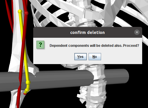
Use of these methods is equivalent to invoking the Delete operation from the context menu in the ArtiSynth GUI, which also looks for dependent components and queries the user for confirmation if any are found (Figure 12.5).
There are situations where one may wish to remove a component but not the components that depend on it. For example, if one wishes to replace a rigid body with a different rigid body, or an FEM model of the same structure, one may wish to transfer to the new body the joints and markers that depend on the original body. This is described more in the following section.
12.5.3 Attaching and transferring to ArtiSynth components
New ArtiSynth components can be attached to OpenSim components through the general point and frame attachment mechanisms described in Sections 3.9, 6.4, and 6.6.
Contact behaviors (Chapter 8) can also be set between OpenSim and/or ArtiSynth components. When working with the former, it may be desirable to replace body surface meshes (using setSurfaceMesh()), or add additional meshes for collision purposes (using addMesh()).
In some instances, one may wish to transfer OpenSim joints, path points, markers or wrap objects to new ArtiSynth components. For joints, one can use the various setBodies() or setBodyA/B() methods described in Section 3.4.3 to reassign one or both bodies for an existing joint.
OpenSim wrap objects are attached to their parent bodies using a frame attachment. Attaching to a different body involves replacing this attachment. However, when doing so, the existing frame attachment must be removed and the existing wrap object should probably be removed from its parent body and placed elsewhere in the component hierarchy. To make this easier, OpenSimParser supplies the method removeWrapObject() that disconnects a wrap object from its parent body and removes its attachment; the application can then move the wrap object elsewhere and reattach it:
For transferring markers and path points to other bodies, OpenSimParser supplies the methods
| Marker replacePathPoint (PointSpringBase muscle, Marker pnt, PointAttachable body) | |
| Marker replaceMarker (Marker mkr, PointAttachable body) | |
replacePathPoint() replaces the path point pnt of the specified muscle with a new point (also implemented as a Marker, though not necessarily a FrameMarker) attached to the specified body. The new point is placed in the same location of the muscle as the original. Similarly, replaceMarker() replaces the marker mkr within the marker set with a new marker attached to the specified body.
12.5.4 Example: replacing the elbow joint with a contact FEM model
The model
artisynth.demos.opensim.Arm26FemElbow
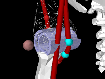
presents a modified version of OpenSimArm26 in which the elbow joint has been removed and replaced with a (very simple) contact model involving two nested FEM cylinders simulating cartilage layers, with the outer layer attached to the lower arm and the inner one attached to the humerus (Figure 12.6). Additional stability is supplied by a FrameSpring, located where the elbow joint was, that prevents sliding and limits rotation along and about the joint axis. The class definition, excluding import statements, is shown below:
In the build() method, super.build() is first called to create the OpenSimArm26 model which this example extends. Then the geometry folder is located relative to the model’s source folder (line 25), and the humerus, lower arm, and elbow components are located using the parser’s findBody() and findJoint() methods (lines 25-30).
The FEM models used to simulate the inner and outer cartilage layers are defined with respect to the elbow’s D frame, which is located in world coordinates using its getCurrentTDW() method (line 35). The models themselves, which are defined as Gmsh files in the geometry folder, are read using GmshReader (Section 6.2.2), initialized with the helper method initializeFem() which sets their material and rendering properties (lines 5-19), transformed to the D frame, and added to the MechModel (lines 40-48). The inner and outer layers are then connected to the humerus and lower arm, respectively, by attaching nodes whose numbers are specified by node number files (Section 6.4.6) also located in the geometry folder (lines 52-60).
With the cartilage models connected, the elbow joint is removed (line 64). It
is replaced by a FrameSpring (lines 65-74) to supply the stabilization
effected by other tissues surrounding the joint. The spring is centered on the
D frame, and uses a PowerFrameMaterial
(Section 3.7.2.1) with all stiffnesses set to 0 except for
a translational stiffness along ![]() to limit sliding along the joint axis, and
a rotational stiffness (with a deadband of
to limit sliding along the joint axis, and
a rotational stiffness (with a deadband of ![]() ) about
) about ![]() to limit joint axis
rotation to the approximate range
to limit joint axis
rotation to the approximate range ![]() .
.
Note the use of setUseTransformDC(false) when setting up the FrameSpring. As described in Section 3.7.1, this makes the spring compute its restoring forces using
, which is the same displacement used by joints, instead of its inverse
. This in turn means that translations and rotations will have the same directionality in the spring as in the original joint.
Frictionless contact is enabled between the cartilage models (lines 77-78), and to improve stability this contact is made compliant (Section 8.7.1, lines 80-82) and the model’s step size is decreased to 0.005 sec (line 83).
Removal of the elbow joint revealed that the quiescent forces in the muscles "BIClong" and "BRA" were large enough to cause a large upward impulse at the start of the simulation. To eliminate this, the tendon slack length for these muscles is reset to equal the difference between the total muscle length and the optimal fibre length (lines 87-91; this calculation uses the fact that the optimal pennation angle is 0). To further reduce initial forces, the bias excitations present in the OpenSim model are also removed (line 93). Finally, to enable the FEM joint to be seen, the wrap object "TRI" is made invisible (line 96).
To run this example in ArtiSynth, select All demos > opensim > Arm26FemElbow from the Models menu.
It is possible to make this model go unstable, usually with an “inverted elements” error, if sufficiently large or abrupt forces are exerted on it via the pull controller or the excitation panel.
12.5.5 Example: replacing the humerus with a FEM model
The model
artisynth.demos.opensim.Arm26FemHumerus
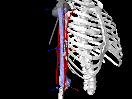
presents a modified version of OpenSimArm26 in which the humerus has been replaced with an FEM model, with the joints, wrap objects, and muscle path points transferred from the humerus body to the FEM model (Figure 12.7). Most of this transfer is based on three Frame objects that are attached to the top, middle and center of the FEM model, using the methods described in Section 6.6. These frames serve as anchors for attaching the shoulder and elbow joints, the wrap objects, and the muscle path points that are far enough from the FEM that direct point-to-FEM connections are problematic. Forces applied to wrap objects and path points are transmitted to the FEM model via the frames, which are given a large number of supporting nodes so that the resulting stresses are distributed across a reasonable number of elements.
The build() method for Arm26FemHumerus makes use of the following helper methods:
nearestFrame() finds the frame whose origin is nearest to a given
position vector. createFrameAttachment() creates a FrameFem3dAttachment (Section 6.6) for a frame
located at the pose described by TFW and supported by a set of nodes that
are within a prescribed distance of the frame’s ![]() axis. This choice of
supporting nodes is based on the fact that much of the force in this model
involves moments about the
axis. This choice of
supporting nodes is based on the fact that much of the force in this model
involves moments about the ![]() axis, but other choices are possible. The
critical point is to choose enough nodes so that stresses induced by frame forces
are distributed reasonably well within the model. The method addFemFrame() creates a Frame object initially located at
TFW, gives it a name, and attaches it to a FEM model using an
attachment created by createFrameAttachment().
axis, but other choices are possible. The
critical point is to choose enough nodes so that stresses induced by frame forces
are distributed reasonably well within the model. The method addFemFrame() creates a Frame object initially located at
TFW, gives it a name, and attaches it to a FEM model using an
attachment created by createFrameAttachment().
The build() method itself is listed below:
First, super.build() is called to create the OpenSimArm26 model which this example extends. The parser’s findBody() method is then used to locate the humerus body that is being replaced (line 45).
The FEM model replacing the humerus body is created and added to the MechModel at lines (47-66). A tetrahedral element mesh is created from a surface mesh (read from a geometry directory) by FemFactory.createFromMesh(). Material properties are assigned, with the FEM model given the same density as that of the humerus body (which is higher than bone density to account for the mass of surrounding tissue). Since the defining surface mesh uses the same coordinate system as the original humerus mesh, the model geometry can be transformed into the correct position using the pose of the humerus body (line 59).
The remainder of the build() method transfers the joints, wrap objects, muscle path points and markers from the humerus body to the FEM model. Joints are transferred at lines 60-76. The humerus corresponds to body A of the shoulder joint and body B of the elbow joint, and so setBodyA() and setBodyB() are used, respectively, to reconnect these to the FEM model at the shoulder’s C frame and the elbow’s D frame. Attachments are generated by createFrameAttachment(), using the world locations of the C and D frames returned by the joint methods getCurrentTCW() and getCurrentTDW().
At lines 81-88, addFemFrame() is used to create and attach three anchoring frames to the top, middle and bottom of the FEM model. The top and bottom frames are located at the C and D frames of the shoulder and elbow joints, while the middle frame is placed at an offset from the C frame. All wrap objects connected to the humerus body are reconnected to one of these frames (lines 91-100). For each wrap object, the parser’s removeWrapObject() removes it from the OpenSim component hierarchy and deletes its attachment, the object is cast to a RigidBody and added to the MechModel’s default rigid body list (other locations could be used), and a new attachment is created between the wrap object and the nearest anchor frame.
The muscle path points are transferred at lines 104-123. The code iterates through all the points of all the muscles. Since OpenSimParser implements all path points as FrameMarkers, each point can be cast to a FrameMarker and inspected to see if its frame is the original humerus body. If it is, the point must be replaced with a new marker attached to the FEM model. If the point is either the first or last path point, then it is an origin or insertion and so is near enough to the FEM model that it can be attached directly. Otherwise, it is attached to the nearest anchor frame. Point replacement is performed by the parser’s replacePathPoint() method.
Lastly, the "r_humerus_epicondyle" marker is transferred to the bottom anchor frame, using the parser’s replaceMarker() method, and the humerus body is removed from the body set. There is no need to do this removal using the ComponentUtils method deleteComponentAndDependencies() since all dependencies have been removed by the preceding steps.
To run this example in ArtiSynth, select All demos > opensim > Arm26FemHumerus from the Models menu.
![[LOGO]](data:image/png;base64,iVBORw0KGgoAAAANSUhEUgAAAAsAAAAOCAYAAAD5YeaVAAAAAXNSR0IArs4c6QAAAAZiS0dEAP8A/wD/oL2nkwAAAAlwSFlzAAALEwAACxMBAJqcGAAAAAd0SU1FB9wKExQZLWTEaOUAAAAddEVYdENvbW1lbnQAQ3JlYXRlZCB3aXRoIFRoZSBHSU1Q72QlbgAAAdpJREFUKM9tkL+L2nAARz9fPZNCKFapUn8kyI0e4iRHSR1Kb8ng0lJw6FYHFwv2LwhOpcWxTjeUunYqOmqd6hEoRDhtDWdA8ApRYsSUCDHNt5ul13vz4w0vWCgUnnEc975arX6ORqN3VqtVZbfbTQC4uEHANM3jSqXymFI6yWazP2KxWAXAL9zCUa1Wy2tXVxheKA9YNoR8Pt+aTqe4FVVVvz05O6MBhqUIBGk8Hn8HAOVy+T+XLJfLS4ZhTiRJgqIoVBRFIoric47jPnmeB1mW/9rr9ZpSSn3Lsmir1fJZlqWlUonKsvwWwD8ymc/nXwVBeLjf7xEKhdBut9Hr9WgmkyGEkJwsy5eHG5vN5g0AKIoCAEgkEkin0wQAfN9/cXPdheu6P33fBwB4ngcAcByHJpPJl+fn54mD3Gg0NrquXxeLRQAAwzAYj8cwTZPwPH9/sVg8PXweDAauqqr2cDjEer1GJBLBZDJBs9mE4zjwfZ85lAGg2+06hmGgXq+j3+/DsixYlgVN03a9Xu8jgCNCyIegIAgx13Vfd7vdu+FweG8YRkjXdWy329+dTgeSJD3ieZ7RNO0VAXAPwDEAO5VKndi2fWrb9jWl9Esul6PZbDY9Go1OZ7PZ9z/lyuD3OozU2wAAAABJRU5ErkJggg==)